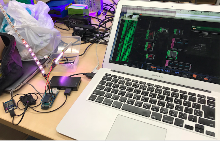
ArtNet DMX (舞台照明などの設備制御で使用されるDMXのネットワーク実装プロトコル) を使用して TouchDesigner / QLC+ (Q Light Controller+) から ESP8266 / ESP32 に接続された NeoPixel LEDテープ(WS2812) を Lチカ してみた。
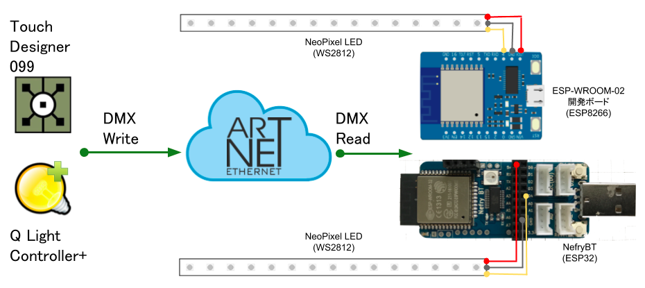
接続構成・配線図
ESP8266 は ESP-WROOM-02 開発ボード を、ESP32 は Nefry BT を、使用した。Nefry BT はリビジョンが存在し、リビジョンによってピン配列が異なるので こちら でチェック。( 今回は無印 (R1) を使用した。)
接続ピン
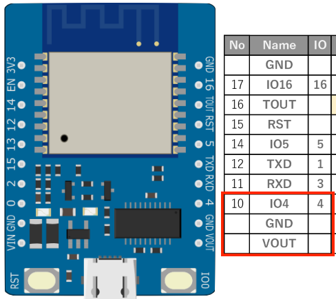
ESP-WROOM-02 開発ボード
VOUT(5V)、GND、IO4(GPIO4) を使用。
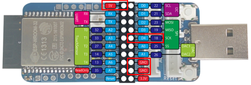
Nefry BT (R1)
5V、GND、D4(GPIO18) を使用。
NeoPixel LED (WS2812)
+5V、GND、DI を使用。

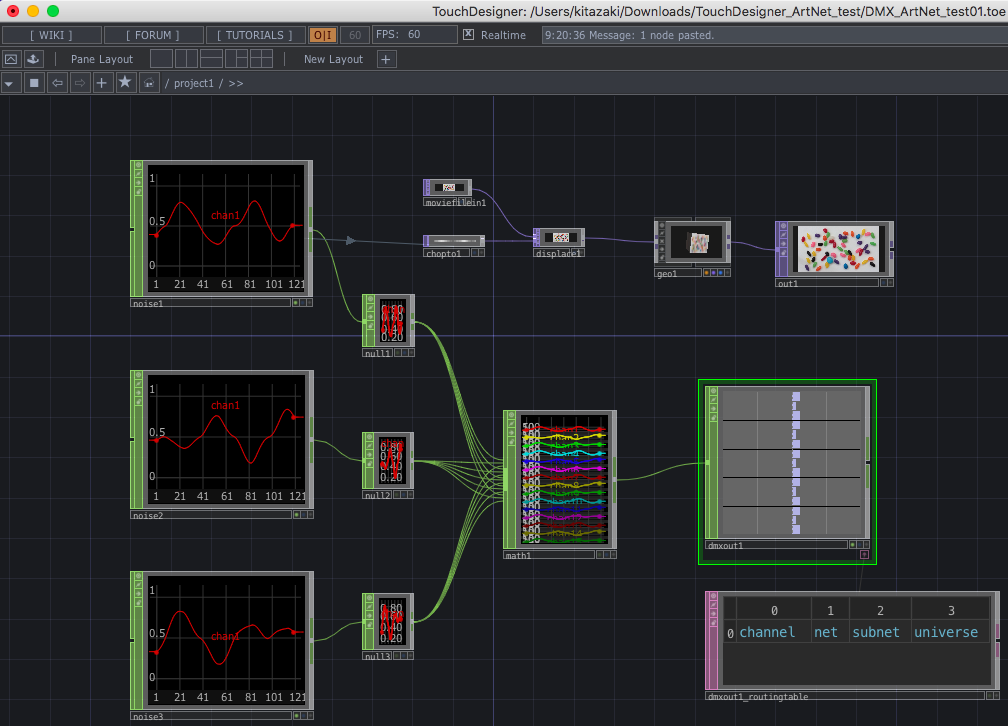
TouchDesighner
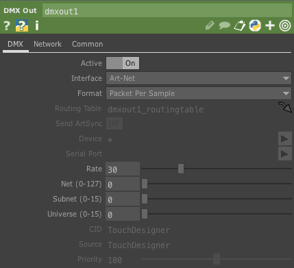
DMX Out オペレータのパラメータ(DMXタブ)
Interface は Art-Net を選択する。
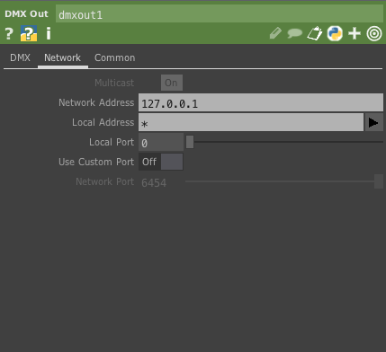
DMX Out オペレータのパラメータ (Networkタブ)
Network Address を適切に設定する。(ネットワーク全体 = ブロードキャストの場合は 255.255.255.255)
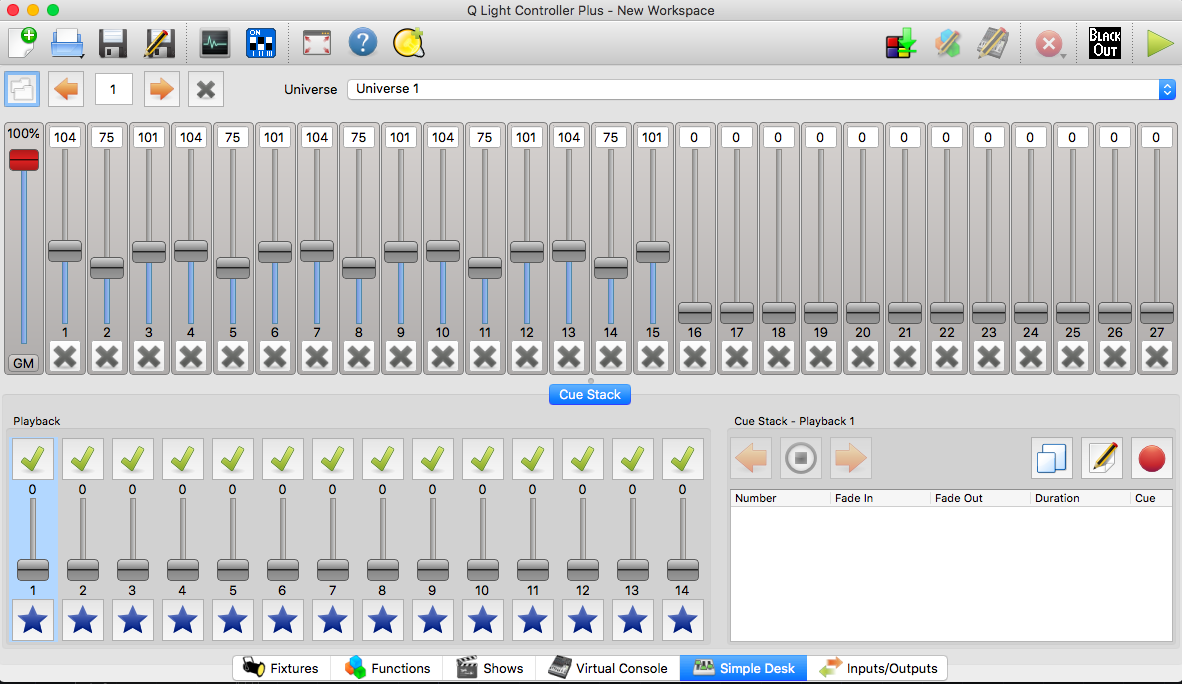
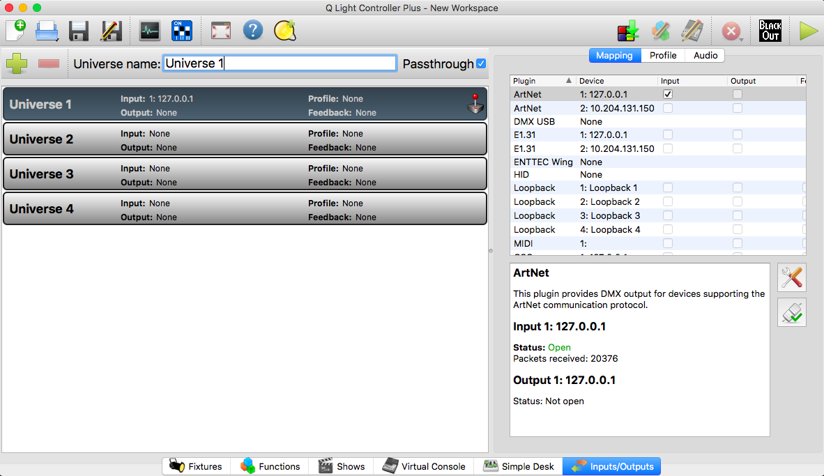
QLC+
Inputs/Outputs タブの Mapping
Plugin の ArtNet の Output にチェックする。
ソースコード
前提条件として ArtNet WiFi ライブラリ と FastLED ライブラリ が必要になるので、Arduino IDE を使用している場合は、ライブラリをダウンロードして「スケッチ」→「ライブラリをインクルード」→「ZIP形式のライブラリをインストール」の手順でインストールする。(参考)
ESP8266 のサンプルコードは こちら。
ESP32 のサンプルコードは こちら。
TouchDesigner のサンプルファイルは こちら。
# include <ESP8266WiFi.h>
# include <WiFiUdp.h>
# include <ArtnetWifi.h>
# include <FastLED.h>

// Wifi settings - be sure to replace these with the WiFi network that your computer is connected to
const char* ssid = "";  // Wi-Fi SSID
const char* password = "";  // Wi-Fi Password

// LED Strip
const int numLeds = 20;  // Change if your setup has more or less LED's
const int numberOfChannels = numLeds * 3;  // Total number of DMX channels you want to receive (1 led = 3 channels)
# define DATA_PIN 4  // The data pin that the WS2812 strips are connected to.
                    // ESP-WROOM-02 Dev.Board D4=GPIO4
CRGB leds[numLeds];

// Artnet settings
ArtnetWifi artnet;
const int startUniverse = 0;

bool sendFrame = 1;
int previousDataLength = 0;

// connect to wifi – returns true if successful or false if not
boolean ConnectWifi(void)
{
  boolean state = true;
  int i = 0;

  WiFi.begin(ssid, password);
  Serial.println("");
  Serial.println("Connecting to WiFi");

  // Wait for connection
  Serial.print("Connecting");
  while (WiFi.status() != WL_CONNECTED) {
    delay(500);
    Serial.print(".");
    if (i > 20){
      state = false;
      break;
    }
    i++;
  }
  if (state){
    Serial.println("");
    Serial.print("Connected to ");
    Serial.println(ssid);
    Serial.print("IP address: ");
    Serial.println(WiFi.localIP());
  } else {
    Serial.println("");
    Serial.println("Connection failed.");
  }

  return state;
}

void onDmxFrame(uint16_t universe, uint16_t length, uint8_t sequence, uint8_t* data)
{
  sendFrame = 1;
  // set brightness of the whole strip
  if (universe == 15)
  {
    FastLED.setBrightness(data[0]);
  }
  // read universe and put into the right part of the display buffer
  for (int i = 0; i < length / 3; i++)
  {
    int led = i + (universe - startUniverse) * (previousDataLength / 3);
    if (led < numLeds)
    {
      leds[led] = CRGB(data[i * 3], data[i * 3 + 1], data[i * 3 + 2]);
    }
  }
  previousDataLength = length;
  FastLED.show();
}

void setup()
{
  Serial.begin(115200);
  ConnectWifi();
  artnet.begin();
  FastLED.addLeds<WS2812, DATA_PIN, GRB>(leds, numLeds);

  // onDmxFrame will execute every time a packet is received by the ESP32
  artnet.setArtDmxCallback(onDmxFrame);
}

void loop()
{
  // we call the read function inside the loop
  artnet.read();
}
# include <WiFi.h>
# include <WiFiUdp.h>
# include <ArtnetWifi.h>
# include <FastLED.h>

// Wifi settings - be sure to replace these with the WiFi network that your computer is connected to
const char* ssid = "";  // Wi-Fi SSID
const char* password = "";  // Wi-Fi Password

// LED Strip
const int numLeds = 20;  // Change if your setup has more or less LED's
const int numberOfChannels = numLeds * 3;  // Total number of DMX channels you want to receive (1 led = 3 channels)
# define DATA_PIN 18  // The data pin that the WS2812 strips are connected to.
                     // NefryBT D4=GPIO18
CRGB leds[numLeds];

// Artnet settings
ArtnetWifi artnet;
const int startUniverse = 0;

bool sendFrame = 1;
int previousDataLength = 0;

// connect to wifi – returns true if successful or false if not
boolean ConnectWifi(void)
{
  boolean state = true;
  int i = 0;

  WiFi.begin(ssid, password);
  Serial.println("");
  Serial.println("Connecting to WiFi");

  // Wait for connection
  Serial.print("Connecting");
  while (WiFi.status() != WL_CONNECTED) {
    delay(500);
    Serial.print(".");
    if (i > 20){
      state = false;
      break;
    }
    i++;
  }
  if (state){
    Serial.println("");
    Serial.print("Connected to ");
    Serial.println(ssid);
    Serial.print("IP address: ");
    Serial.println(WiFi.localIP());
  } else {
    Serial.println("");
    Serial.println("Connection failed.");
  }

  return state;
}

void onDmxFrame(uint16_t universe, uint16_t length, uint8_t sequence, uint8_t* data)
{
  sendFrame = 1;
  // set brightness of the whole strip
  if (universe == 15)
  {
    FastLED.setBrightness(data[0]);
  }
  // read universe and put into the right part of the display buffer
  for (int i = 0; i < length / 3; i++)
  {
    int led = i + (universe - startUniverse) * (previousDataLength / 3);
    if (led < numLeds)
    {
      leds[led] = CRGB(data[i * 3], data[i * 3 + 1], data[i * 3 + 2]);
    }
  }
  previousDataLength = length;
  FastLED.show();
}

void setup()
{
  Serial.begin(115200);
  ConnectWifi();
  artnet.begin();
  FastLED.addLeds<WS2812, DATA_PIN, GRB>(leds, numLeds);

  // onDmxFrame will execute every time a packet is received by the ESP32
  artnet.setArtDmxCallback(onDmxFrame);
}

void loop()
{
  // we call the read function inside the loop
  artnet.read();
}
まとめ
TouchDesigner などのノード系ビジュアルプログラミングソフトや QLC+ などの照明設備制御ソフトと IoT デバイスとの相性は非常に良いことが分かったので、今後 "よさみ" がさらに深まれば幸いです。
