こちらを参考にしながら、PICを焼いて、Lチカしてみる
やること
- PICの解説
- 開発環境の構築
- PICにプログラムを書き込む為の回路を構築
- コードを実装、コンパイル、PICに書き込む(今回)
- Lチカ回路の構築、動作確認
コードを実装
プロジェクトの設定
MPLAB IDEを起動
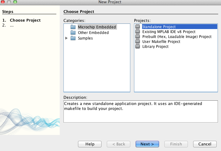
New Project を選択
Microchip Embedded -> Standalone Project
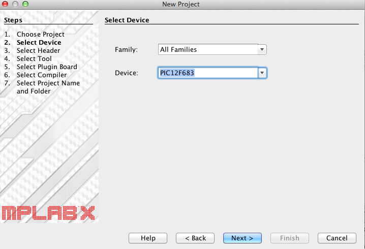
デバイスを聞かれるので PIC12F683 を選択
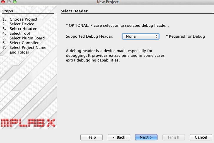
デバッグヘッダをつけるか聞かれるので NONE を選択
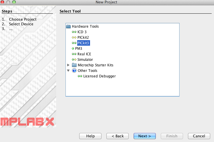
ハードウェアツールを聞かれるので、PICKIT3 を選択
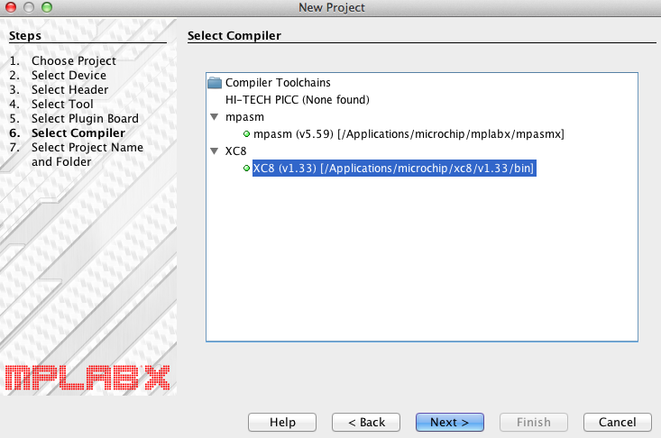
コンパイラを聞かれるので、XC8 を選択
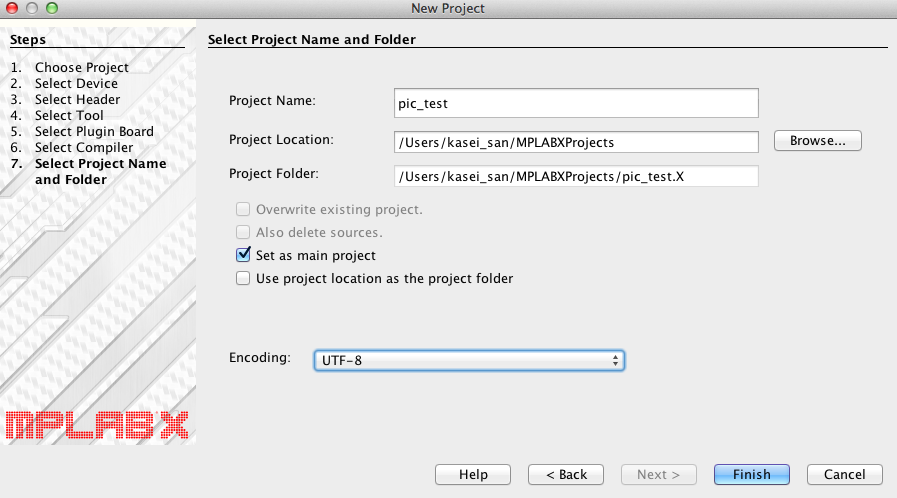
プロジェクト名を聞かれるので、適当につける
あと、EncodingはUTF-8にしたほうが面倒が少ないと思う
その他設定
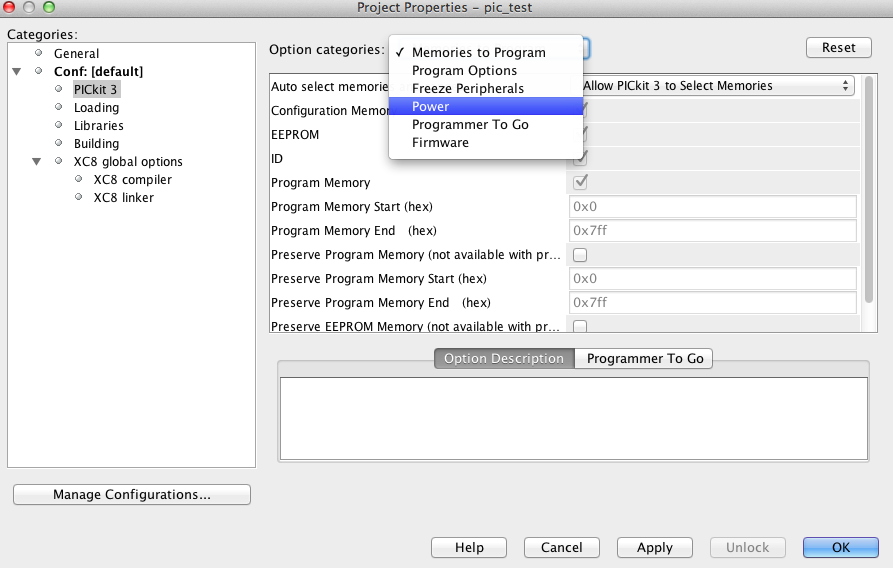
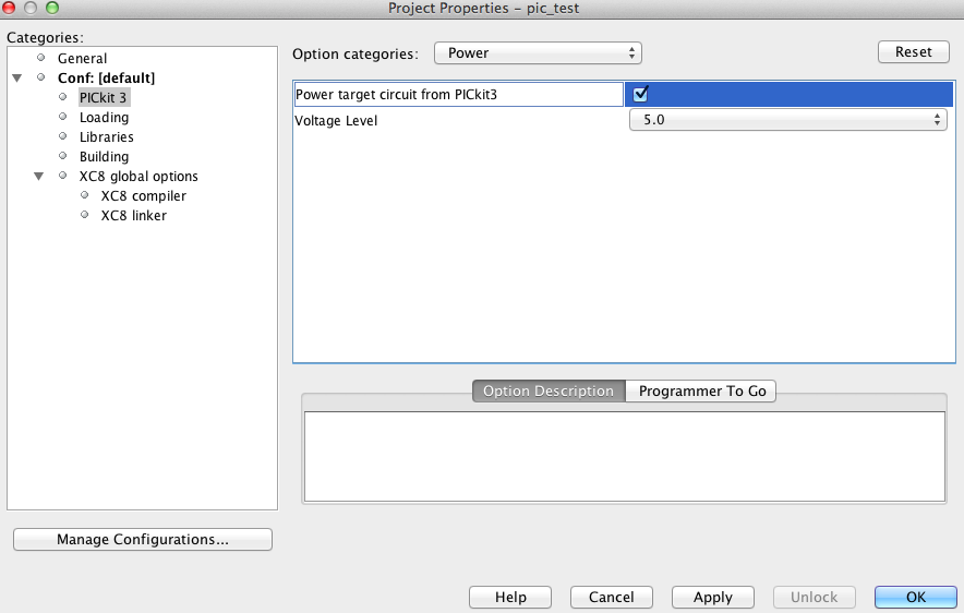
PICKit3 からの給電で動作確認したいので、そのように設定する
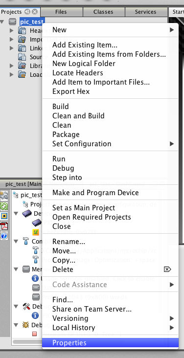
右クリック -> Properties
PICKit3 -> Power
Power target circuit from PICKit3 -> ON
main.c を用意
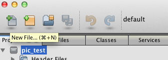
New File を選択
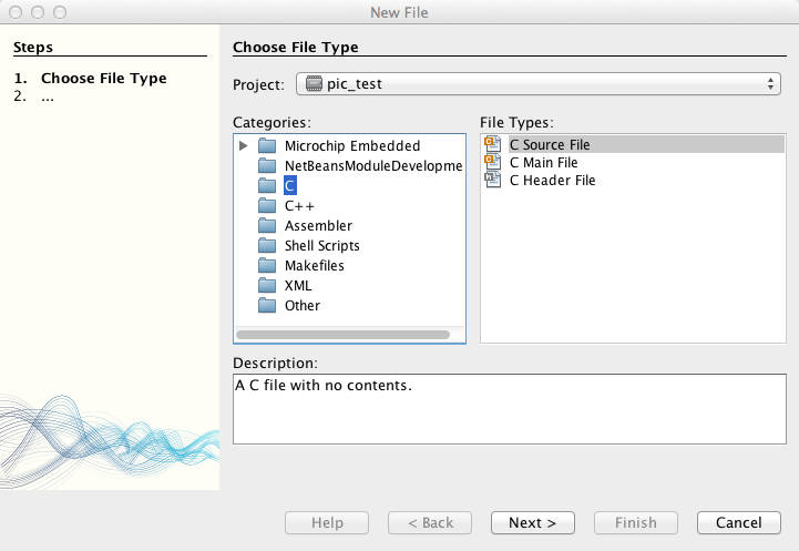
C -> C Source File
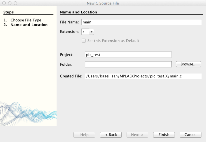
File Name -> main.c
コンフィグレーションビットの設定
コンフィグレーションビットって?
- コンフィグレーション -> PICの色々な設定
- コンフィグレーションビット -> コンフィグレーションが格納されるメモリ領域とその値
マクロを使って実装しておくと、プログラムと一緒にPICKitがPICに書き込む
設定方法
ツールを使って設定が可能
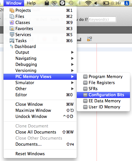
Window -> PIC Memory Views -> Configuration Bits
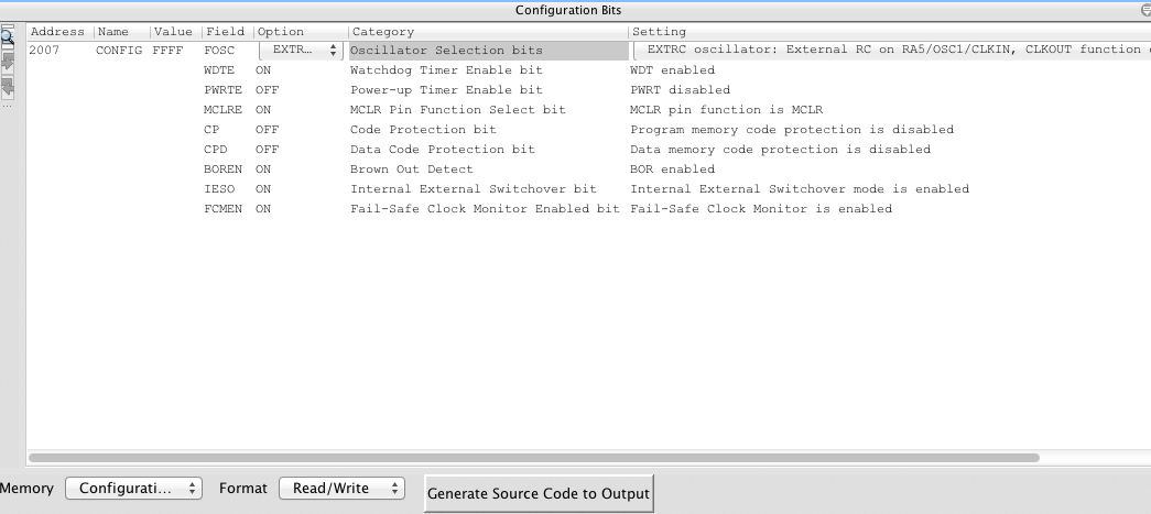
色々設定が出てくる
コンフィグレーションビットの解説
FOSC : 外部クロックの使用有無
今回は内部クロックを使用するのでEXTRCCLK
- クロック : CPUの内部の各回路間の同期を取るために流れる信号
- クロック周波数 : クロックを1秒間に発信させる回数
- 内部クロック : PIC内部にあるクロック
- 外部クロック : PICの外部にクロック(水晶振動子)を用意して、それを使用する
FOSC の設定値
- EXTRCCLK : 内部クロック使用。3番ピンは、内部クロックを出力する(CLKOUT)
- EXTRCIO : 内部クロック使用。3番ピンは、GPIO4 となる
- INTOSCCLK,INTOSCIO,EC : 外部クロックの接続方法毎の設定
- HS, XT, LP : 特定の外部クロックの接続方法で、使用する外部クロックの周波数帯毎の設定
参考
WDTE : ウォッチドッグタイマ
今回はウォッチドッグタイマを使用しないのでOFF
- ON : ウォッチドッグタイマ有効
ウォッチドッグ : プログラムが暴走状態の時にリセットする仕組み
ウォッチドッグの挙動
- PICのプログラムと別に動作していて、タイマをカウントしている
- カウントが一定の値以上になった時に、PICをリセットする
プログラム側
- mainループの最後等で、ウォッチドッグのカウントをリセットするコードを実装する
プログラム動作時の挙動
- 正常動作 : PICはリセットされない
- 暴走状態 : カウントがリセットされなくなった時に、PICをリセット
PWRTE : パワーアップタイマ
通常ONでOK
電源起動時の不安定な状態から回路を保護する
- ON : 電源ONになってから、回路が安定するまでPICを起動させない
MCLRE : MCLRピンの使い道
今回はMCLRとして使う予定なのでON
- ON : 4番ピンをMCLRとして使用
- OFF : 4番ピンをGPIO3として使用
CP : コードプロテクト
デバッグ時はOFFでOK
- ON : PICからのコードの読み出しを許可しない
CPD : データプロテクト
デバッグ時はOFFでOK
- ON : PICからのデータの読み出しを許可しない
BOREN : ブラウンアウト
今回はON
ブラウンアウト : 電源が不安定な状態
ブラウンアウト時の挙動を決める
- ON : PICを停止する
- OFF : なにもしない
- NSLEEP : 通常動作時:ON, スリープ時:OFF
- SBOREN : プログラム上でBORENの設定する
IESO : 2段階クロック
今回は外部クロックを使用しないのでOFF
- ON : 外部クロックを使用する時に、電源立ち上がり時に、外部クロックが安定するまで、内部クロックを設定する
FCMEN : バックアップクロック
今回は外部クロックを使用しないのでOFF
- ON : 外部クロックが何かしらの理由で停止した時に、内部クロックを使用する
コンフィグレーションビットの設定をコードにする
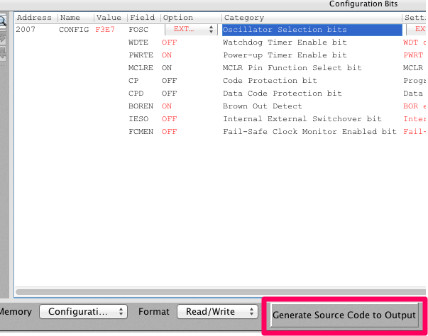
こんな感じに設定したら Generate Souce Code to Output をクリック
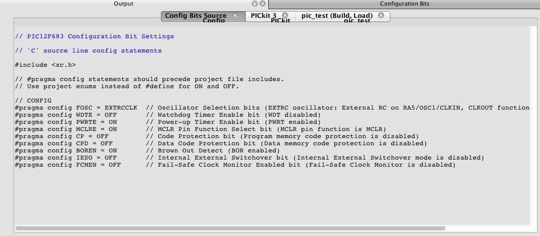
出力内容を main.c にコピペする
main.c の実装
1秒毎にLEDを点滅させるコードを実装
// PIC12F683 Configuration Bit Settings

// 'C' source line config statements

# include <xc.h>

// #pragma config statements should precede project file includes.
// Use project enums instead of #define for ON and OFF.

// CONFIG
# pragma config FOSC = EXTRCCLK  // Oscillator Selection bits (EXTRC oscillator: External RC on RA5/OSC1/CLKIN, CLKOUT function on RA4/OSC2/CLKOUT pin)
# pragma config WDTE = OFF       // Watchdog Timer Enable bit (WDT disabled)
# pragma config PWRTE = ON       // Power-up Timer Enable bit (PWRT enabled)
# pragma config MCLRE = ON       // MCLR Pin Function Select bit (MCLR pin function is MCLR)
# pragma config CP = OFF         // Code Protection bit (Program memory code protection is disabled)
# pragma config CPD = OFF        // Data Code Protection bit (Data memory code protection is disabled)
# pragma config BOREN = ON       // Brown Out Detect (BOR enabled)
# pragma config IESO = OFF       // Internal External Switchover bit (Internal External Switchover mode is disabled)
# pragma config FCMEN = OFF      // Fail-Safe Clock Monitor Enabled bit (Fail-Safe Clock Monitor is disabled)

# define _XTAL_FREQ  4000000 // クロック周波数(4MHz)

void main(void) {

    // 特殊レジスタ(SFR)の設定
    OSCCON = 0x40;  //クロック周波数を1MHzに設定
    ANSEL  = 0x00;  //すべてのピンをデジタルモードに設定
    TRISIO = 0x00;  //すべてのピンを出力に設定

    while(1){ // main loop
        __delay_ms(1000); // 1000ms待機
        GP5 = 1;          // GP5をHIGHにする
        __delay_ms(1000); // 1000ms待機
        GP5 = 0;          // GP5をLOWにする
    }
}
_XTAL_FREQ で、クロック周波数を指定
データシートによると
Software selectable frequency range of8 MHz to 125 kH
らしいので、その範囲内にする
特殊レジスタ(SFR)
Special Function Resisterの略で、CPUと、その周辺機能を制御するためのレジスタ
The Special Function Registers are registers used by the CPU and peripheral functions for controlling the desired operation of the device
色々なレジスタがあるが、それぞれデータシートに詳細があるので、そちらを参照
今回は、GPIO周りと、クロック周波数の設定についての部分だけ解説
それぞれ、以下のように特殊な変数の値を書き換えることで、SFRの値の変更が可能
    // 特殊レジスタ(SFR)の設定
    OSCCON = 0x40;  //クロック周波数を1MHzに設定
    ANSEL  = 0x00;  //すべてのピンをデジタルモードに設定
    TRISIO = 0x00;  //すべてのピンを出力に設定
変数の一覧については、データシートと、
MBLAB の Window -> PIC Memory Vies -> SFRs を参照
OSCCON
- Oscillator Control (発信機制御)の略
- 発信機に関する制御の為のレジスタ
- 全8ビットで、(0ビット目から数えて)6-4bit目が内部発信機を使用した場合の周波数の設定になる
bit 6-4
IRCF<2:0>:Internal Oscillator Frequency Select bits
  111 = 8MHz
  110 = 4 MHz (default)
  101 = 2MHz
  100 = 1MHz
  011 = 500kHz
  010 = 250kHz
  001 = 125kHz
  000 = 31 kHz (LFINTOSC
_XTAL_FREQ との違いは?
- _XTAL_FREQ は、__delay_ms 等をコンパイルする時に使用する定数
- OSCCON は、PICが自身の発信機の設定がどのようなものであるかを知るためのレジスタ
だとおもう
ANSEL
The ANSEL register is used to configure the Input mode of an I/O pin to analog.
Setting the appropriate ANSEL bit high will cause all digital reads on the pin to
be read as ‘0’ and allow analog functions on the pin to operate correctly
- GPIOの入力モードをアナログ/デジタルに設定する為のレジスタ
- 今回は全てデジタル出力モードなので、0x00 を設定
- 今回は全て出力モードなので、ANSELは設定しなくても動作するかも(未調査)
TRISIO
Setting a TRISIO bit (=1) will make the corresponding GPIO pin an input (i.e., put the corresponding output driver in a High-Impedance mode).
Clearing a TRISIO bit (=0) will make the corresponding GPIO pin an output
- GPIOのI/Oを設定する為のレジスタ
- 1がInput, 0がOutput
- 0〜5bit目が、それぞれGP0〜GP5に対応している
- 今回は、Outputのみなので、0x00 を設定
コンパイル
画面上のハンマーのボタン押下でビルドされる
CLEAN SUCCESSFUL (total time: 55ms)
make -f nbproject/Makefile-default.mk SUBPROJECTS= .build-conf
make[1]: Entering directory '/Users/kasei_san/MPLABXProjects/pic_test.X'
make  -f nbproject/Makefile-default.mk dist/default/production/pic_test.X.production.hex
make[2]: Entering directory '/Users/kasei_san/MPLABXProjects/pic_test.X'
"/Applications/microchip/xc8/v1.33/bin/xc8" --pass1  --chip=12F683 -Q -G  --double=24 --float=24 --opt=default,+asm,+asmfile,-speed,+space,-debug --addrqual=ignore --mode=free -P -N255 --warn=0 --asmlist --summary=default,-psect,-class,+mem,-hex,-file --output=default,-inhx032 --runtime=default,+clear,+init,-keep,-no_startup,+osccal,-resetbits,-download,-stackcall,+clib --output=-mcof,+elf:multilocs --stack=compiled:auto:auto "--errformat=%f:%l: error: (%n) %s" "--warnformat=%f:%l: warning: (%n) %s" "--msgformat=%f:%l: advisory: (%n) %s"    -obuild/default/production/main.p1  main.c
"/Applications/microchip/xc8/v1.33/bin/xc8"  --chip=12F683 -G -mdist/default/production/pic_test.X.production.map  --double=24 --float=24 --opt=default,+asm,+asmfile,-speed,+space,-debug --addrqual=ignore --mode=free -P -N255 --warn=0 --asmlist --summary=default,-psect,-class,+mem,-hex,-file --output=default,-inhx032 --runtime=default,+clear,+init,-keep,-no_startup,+osccal,-resetbits,-download,-stackcall,+clib --output=-mcof,+elf:multilocs --stack=compiled:auto:auto "--errformat=%f:%l: error: (%n) %s" "--warnformat=%f:%l: warning: (%n) %s" "--msgformat=%f:%l: advisory: (%n) %s"     -odist/default/production/pic_test.X.production.elf  build/default/production/main.p1
:: warning: (1273) Omniscient Code Generation not available in Free mode
Microchip MPLAB XC8 C Compiler (Free Mode) V1.33
Part Support Version: 1.33 (A)
Copyright (C) 2014 Microchip Technology Inc.
License type: Node Configuration


Memory Summary:
    Program space        used    22h (    34) of   800h words   (  1.7%)
    Data space           used     5h (     5) of    80h bytes   (  3.9%)
    EEPROM space         used     0h (     0) of   100h bytes   (  0.0%)
    Data stack space     used     0h (     0) of    50h bytes   (  0.0%)
    Configuration bits   used     1h (     1) of     1h word    (100.0%)
    ID Location space    used     0h (     0) of     4h bytes   (  0.0%)


Running this compiler in PRO mode, with Omniscient Code Generation enabled,
produces code which is typically 40% smaller than in Free mode.
See http://microchip.com for more information.

make[2]: Leaving directory '/Users/kasei_san/MPLABXProjects/pic_test.X'
make[1]: Leaving directory '/Users/kasei_san/MPLABXProjects/pic_test.X'

BUILD SUCCESSFUL (total time: 723ms)
Loading code from /Users/kasei_san/MPLABXProjects/pic_test.X/dist/default/production/pic_test.X.production.hex...
Loading completed
BUILD SUCCESSFULと、でればビルド成功
PICに書き込む
画面上のICに矢印が向いているボタン押下で書き込まれる
*****************************************************

Connecting to MPLAB PICkit 3...
Firmware Suite Version.....01.34.11
Firmware type..............Midrange

Target detected
Device ID Revision = 3

The following memory area(s) will be programmed:
program memory: start address = 0x0, end address = 0x7ff
configuration memory
Device Erased...

Programming...
Programming/Verify complete
参考
-
ツール・ラボ » MacでPICマイコン電子工作入門(19)
- FOSCと外部クロックについて解説
-
ツール・ラボ » MacでPICマイコン電子工作入門(20)
- FOSC以外のコンフィグレーションビットについて解説
-
PICマイコン 特殊な指定と宣言 - パレットソフト
- コンフィグレーションビットについて解説
-
電子工作
- コンフィグレーションビットについて解説
- [MPLAB X IDEの基本的な使い方とMCUへのダウンロード方法](http://www.haljion.net/index.php/2013-04-12-08-15-44
/49-microcomputerapplication/305-mplab-x-ide-mcu)- MPLAB X IDE の解説と、コンフィグレーションビットの生成方法
-
http://akizukidenshi.com/download/ds/microchip/pic12f683.pdf
- データシート

