長きにわたって OpenCV の Stitch モジュールについてコードリーディングを進めています。
こちらの記事の続きです。
https://qiita.com/itoshogo3/items/8a1fb067ac4a3ac28a3f
ざっくりとした概要はこちらです。
https://qiita.com/itoshogo3/items/7a3279668b24008a3761
概要
画像のマッピングも終えてイイ感じの縫い目も見つかり、いよいよ最後の工程である画像の合成です。stitch モジュールではマルチバンドブレンドと呼ばれる賢い手法で画像合成を実装しています。こちらは画像の周波数ごとに重みづけを行った値を足し合わせるという方法で、これにより自然な合成が出来上がります。

画像データの周波数の話
まずはマルチバンドブレンドのキモとなる概念である画像データにおける周波数の話をしておきます。普通は周波数と言うと電波とか音のイメージで、1秒間に繰り返される波の数のという認識が一般的かと思います。これは「時間」を軸として値が変化していく様子を表していて、周波数が高いと値の変化が速く、低いとゆっくりと値が変わっていきます。これが画像データの話になると、「空間」を軸として値が変化していくという意味合いで周波数という言葉が使われます。連続するピクセルデータをひとつの波形としてみなすのです。下図のように周波数が低い画像はピクセルの値がなだらかに変化して、ぼやけたような印象になります。逆にピクセルの値が細かく変化するような画像は、周波数が高い画像となります。

ピラミッドの話
続いて画像ピラミッドの話をしておきます。画像ピラミッドとは図のように画像の解像度を半分ずつ下げていったもののことです。図のイメージからピラミッドと名付けられております。

ピラミッドのレベルを一つ下げると画像のサイズが半分になります。ちなみにこちらはガウシアンピラミッドと呼ばれるものになります。画像ピラミッドには他にもラプラシアンピラミッドというものがあります。
ガウシアンピラミッド
ガウシアンピラミッドはレベルを下げていくほど画像のサイズが小さくなりますが、これをまた元のサイズに戻すと下図のようなボケた画像が得られます。というのも、解像度を下げることによって画像の細かいピクセルデータが失われてしまったからです。一度小さくなった画像を無理やり元のサイズ戻そうとする時、失われたピクセルは残ったピクセルから補間して補わなければならず、結果としてボケた画像になるのです。
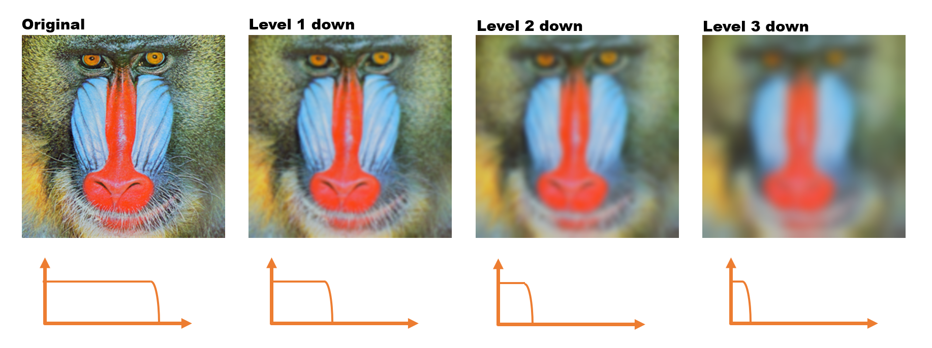
このボケた画像というのはピクセルの細かく変化する成分が失われております。小難しい言葉で言い換えると、高周波成分が取り除かれて低周波成分が残った画像となっているのです。つまり、ガウシアンピラミッドはレベルが下がっていくほど画像の周波数が低くなっていくということになります。
ラプラシアンピラミッド
元の画像とボケた画像の差分をとると画像のエッジ部分だけを抜き出したみたいな画像が得られます。元の画像(全周波数成分入り)からボケた画像(低周波成分のみ)を差し引くことで、画像の高周波成分のみが残ることになるのです。
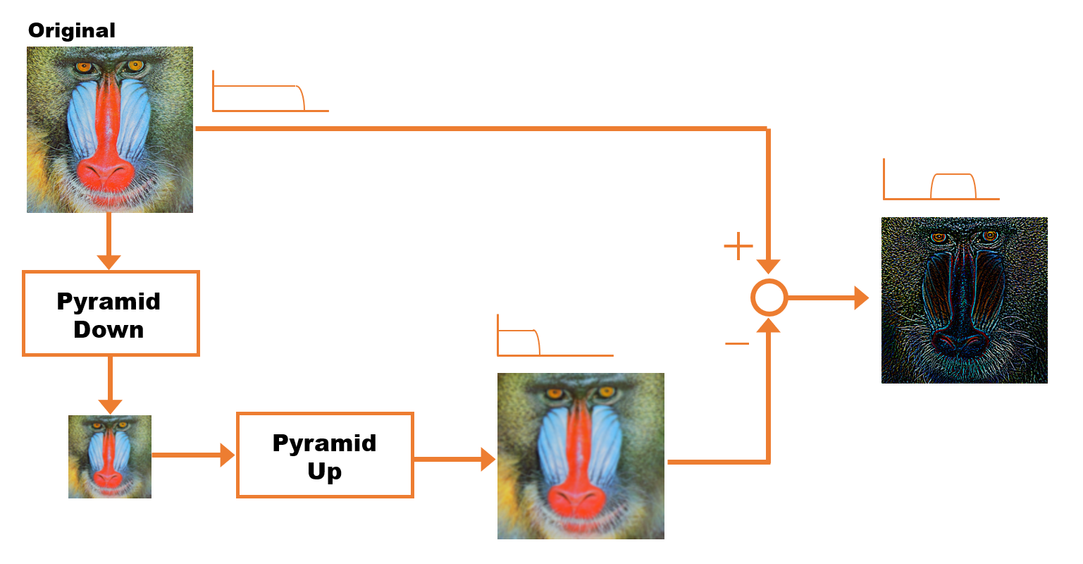
これをガウシアンピラミッドの各レベルで行ったものがラプラシアンピラミッドになります。
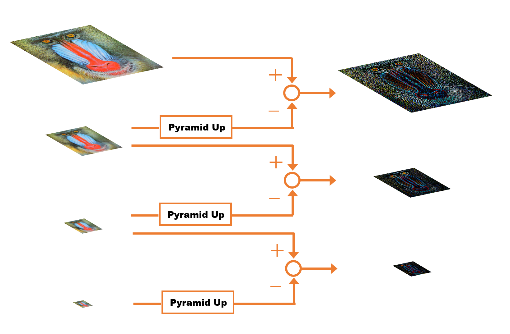
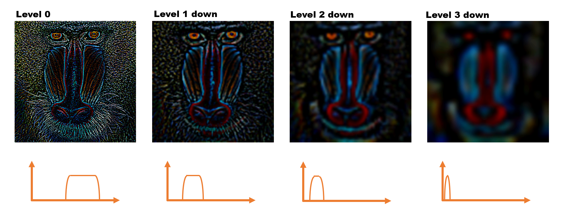
マルチバンドブレンド
マルチバンドブレンドアルゴリズムとは、まず画像を複数の周波数帯(バンド)にわけて、周波数毎にブレンドするというアルゴリズムです。この手法ではとにかくたくさんの画像ピラミッドを作ります。はじめに出力用となる画像をピラミッドで用意しておきます。
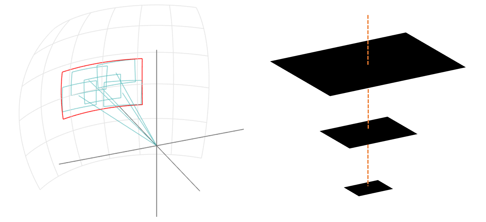
続いて一枚ずつ画像をブレンドしていきますが、いきなり合成するのではなく出力用に用意したピラミッドに対して各レベル毎にブレンドを行っています。具体的な手順は下図のように、画像に対してはラプラシアンピラミッドを、マスクに対してはガウシアンピラミッドをそれぞれ作成し、ピラミッドの各レベルで画像とマスクの重みをかけた値を出力用のピラミッドに格納していきます。

2枚目以降も同じ処理を繰り返してきます。
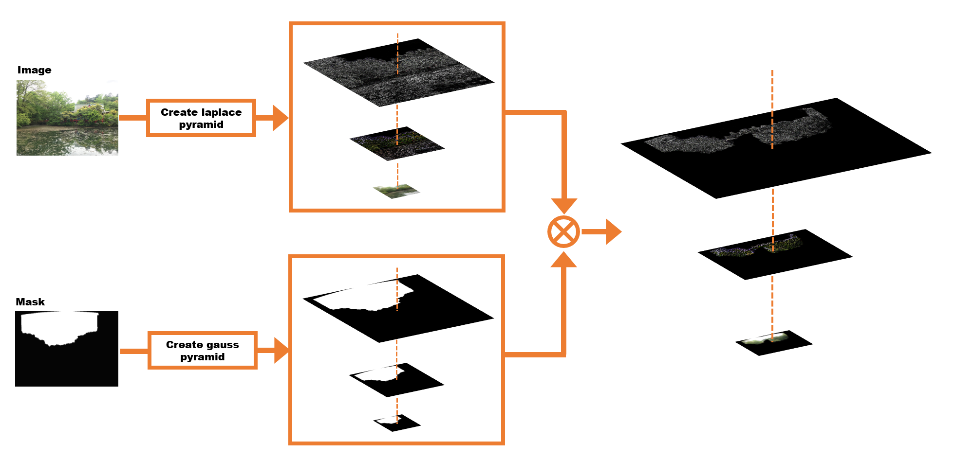
最終的に出力用のピラミッドは下図のような状態になります。

最後にピラミッドの各レベルの画像を元のサイズに戻して周波数の異なる画像をつくり、それらを足し合わせると最終的な合成画像の出来上がりです。
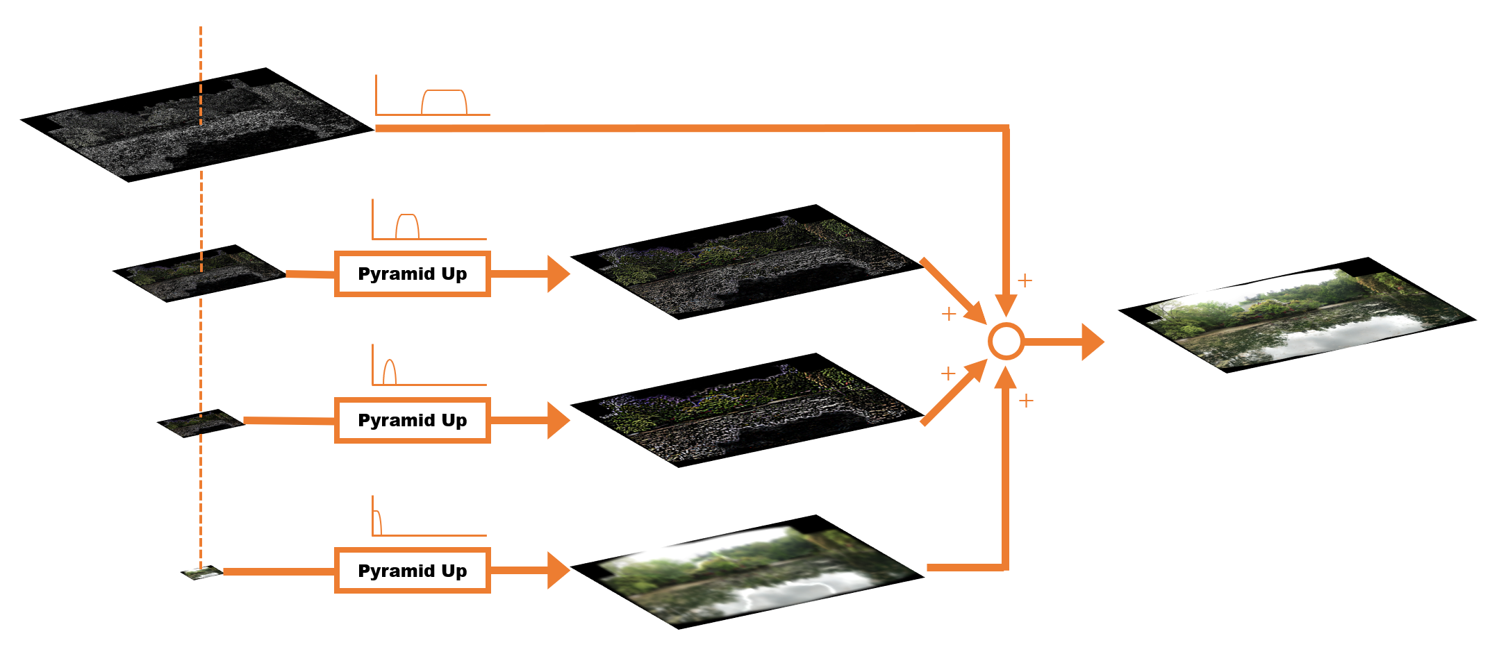
結果はこちらのようになります。

コードリーディング
今回の解説はソースコードでいうと、Stitcher::composePanorama() の後半部分で、簡略化して書くと下記のようになっています。
// 球面にマップされて歪んだ画像
UMat img_warped, img_warped_s;

// マスク画像
UMat dilated_mask, seam_mask, mask, mask_warped;

// 入力画像
UMat full_img, img;

for (size_t img_idx = 0; img_idx < imgs_.size(); ++img_idx)
{
    .
    .
    色んな処理(リサイズ、球面マッピング、露出補正、縫い目マスク生成)
    .
    .

    // 画像をひとつずつブレンダーに食わせる
    blender_->feed(img_warped_s, mask_warped, corners[img_idx]);
}

// ブレンドする
UMat result;
blender_->blend(result, result_mask_);
入力画像にごにょごにょと処理を加えた後、MultiBandBlender::feed() で Blender クラスに一枚ずつ画像を食わせてやって、最後に MultiBandBlender::blend() を実行して出力結果を得ます。
これまでは入力画像のカメラパラメータや縫い目を見つけることが目的だったので、扱いやすいサイズにリサイズした画像をもとに計算を進めていました。入力された画像をそのままのサイズで処理してしまうと負荷が大きくなってしまうためです。リサイズしてもカメラの回転 R の計算結果は変わりません。カメラの内部パラメータ K と縫い目の位置は変わってしまいますが、スケールをかければすぐに元に戻せます。というわけでリサイズした状態で処理を進めても、さして問題なかったわけです。ブレンド処理の for 文の前半では、これまで行ったきた球面マッピング、露出補正、縫い目マスク生成、等の色んな処理を画像の入力サイズを変えてもう一度実行しています。
ブレンダーの準備
for 文の中で1回だけ MultiBandBlender::prepare() が実行されます。この処理の中では、最終的な出力に相当する画像、マスク、画像ピラミッド等の、ブレンド処理で必要とされる画像のメモリを確保しています。
if (!is_blender_prepared)
{
    blender_->prepare(corners, sizes);
    is_blender_prepared = true;
}
MultiBandBlender::prepare() の詳細はこちらです。
void MultiBandBlender::prepare(Rect dst_roi)
{
    dst_roi_final_ = dst_roi;

    // Crop unnecessary bands
    double max_len = static_cast<double>(std::max(dst_roi.width, dst_roi.height));
    num_bands_ = std::min(actual_num_bands_, static_cast<int>(ceil(std::log(max_len) / std::log(2.0))));

    // Add border to the final image, to ensure sizes are divided by (1 << num_bands_)
    dst_roi.width += ((1 << num_bands_) - dst_roi.width % (1 << num_bands_)) % (1 << num_bands_);
    dst_roi.height += ((1 << num_bands_) - dst_roi.height % (1 << num_bands_)) % (1 << num_bands_);

    // 出力領域の確保
    Blender::prepare(dst_roi);

    // ピラミッドの生成
    {
        dst_pyr_laplace_.resize(num_bands_ + 1);
        dst_pyr_laplace_[0] = dst_;

        dst_band_weights_.resize(num_bands_ + 1);
        dst_band_weights_[0].create(dst_roi.size(), weight_type_);
        dst_band_weights_[0].setTo(0);

        for (int i = 1; i <= num_bands_; ++i)
        {
            dst_pyr_laplace_[i].create((dst_pyr_laplace_[i - 1].rows + 1) / 2,
                (dst_pyr_laplace_[i - 1].cols + 1) / 2, CV_16SC3);
            dst_band_weights_[i].create((dst_band_weights_[i - 1].rows + 1) / 2,
                (dst_band_weights_[i - 1].cols + 1) / 2, weight_type_);
            dst_pyr_laplace_[i].setTo(Scalar::all(0));
            dst_band_weights_[i].setTo(0);
        }
    }
}
Blender::prepare() の中身はこちら。dst_roi で指定されたサイズで dst_ と dst_mask_ を生成しています。
void Blender::prepare(Rect dst_roi)
{
    dst_.create(dst_roi.size(), CV_16SC3);
    dst_.setTo(Scalar::all(0));
    dst_mask_.create(dst_roi.size(), CV_8U);
    dst_mask_.setTo(Scalar::all(0));
    dst_roi_ = dst_roi;
}
後半はピラミッドのメモリ領域を確保しています。初期値は全て 0 がセットされています。
for (int i = 1; i <= num_bands_; ++i)
{
    dst_pyr_laplace_[i].create((dst_pyr_laplace_[i - 1].rows + 1) / 2,
        (dst_pyr_laplace_[i - 1].cols + 1) / 2, CV_16SC3);
    dst_band_weights_[i].create((dst_band_weights_[i - 1].rows + 1) / 2,
        (dst_band_weights_[i - 1].cols + 1) / 2, weight_type_);
    dst_pyr_laplace_[i].setTo(Scalar::all(0));
    dst_band_weights_[i].setTo(0);
}
ブレンダーに画像を食わせる
今回のキモである MultiBandBlender::feed() の中身を見ていきます。前の工程の MultiBandBlender::prepare() でピラミッドを用意しましたが、まだ中身は空の状態です。こちらの処理では画像を一枚ずつ読み込んで、用意したピラミッドの値を部分的に更新していき、最終的なブレンドを行うための準備を行います。
GPU を使う使わないの分岐やら重みのタイプの分岐やらで本質的なコードが見にくくなっていたので、理解に必要な部分だけ抜き出す形でコードを書き直してみました。
void MultiBandBlender::feed(InputArray _img, InputArray mask, Point tl)
{
    UMat img;
    img = _img.getUMat();

    // Keep source image in memory with small border
    int gap = 3 * (1 << num_bands_);
    Point tl_new(std::max(dst_roi_.x, tl.x - gap),
                 std::max(dst_roi_.y, tl.y - gap));
    Point br_new(std::min(dst_roi_.br().x, tl.x + img.cols + gap),
                 std::min(dst_roi_.br().y, tl.y + img.rows + gap));

    // Ensure coordinates of top-left, bottom-right corners are divided by (1 << num_bands_).
    // After that scale between layers is exactly 2.
    // We do it to avoid interpolation problems when keeping sub-images only. There is no such problem when
    // image is bordered to have size equal to the final image size, but this is too memory hungry approach.
    tl_new.x = dst_roi_.x + (((tl_new.x - dst_roi_.x) >> num_bands_) << num_bands_);
    tl_new.y = dst_roi_.y + (((tl_new.y - dst_roi_.y) >> num_bands_) << num_bands_);
    int width = br_new.x - tl_new.x;
    int height = br_new.y - tl_new.y;
    width += ((1 << num_bands_) - width % (1 << num_bands_)) % (1 << num_bands_);
    height += ((1 << num_bands_) - height % (1 << num_bands_)) % (1 << num_bands_);
    br_new.x = tl_new.x + width;
    br_new.y = tl_new.y + height;
    int dy = std::max(br_new.y - dst_roi_.br().y, 0);
    int dx = std::max(br_new.x - dst_roi_.br().x, 0);
    tl_new.x -= dx; br_new.x -= dx;
    tl_new.y -= dy; br_new.y -= dy;

    int top = tl.y - tl_new.y;
    int left = tl.x - tl_new.x;
    int bottom = br_new.y - tl.y - img.rows;
    int right = br_new.x - tl.x - img.cols;

    // Create the source image Laplacian pyramid
    UMat img_with_border;
    copyMakeBorder(_img, img_with_border, top, bottom, left, right, BORDER_REFLECT);
    std::vector<UMat> src_pyr_laplace;
    createLaplacePyr(img_with_border, num_bands_, src_pyr_laplace);

    // Create the weight map Gaussian pyramid
    UMat weight_map;
    std::vector<UMat> weight_pyr_gauss(num_bands_ + 1);
    mask.getUMat().convertTo(weight_map, CV_32F, 1./255.);
    copyMakeBorder(weight_map, weight_pyr_gauss[0], top, bottom, left, right, BORDER_CONSTANT);
    for (int i = 0; i < num_bands_; ++i)
        pyrDown(weight_pyr_gauss[i], weight_pyr_gauss[i + 1]);

    int y_tl = tl_new.y - dst_roi_.y;
    int y_br = br_new.y - dst_roi_.y;
    int x_tl = tl_new.x - dst_roi_.x;
    int x_br = br_new.x - dst_roi_.x;

    // Add weighted layer of the source image to the final Laplacian pyramid layer
    for (int i = 0; i <= num_bands_; ++i)
    {
        Rect rc(x_tl, y_tl, x_br - x_tl, y_br - y_tl);
        Mat _src_pyr_laplace = src_pyr_laplace[i].getMat(ACCESS_READ);
        Mat _dst_pyr_laplace = dst_pyr_laplace_[i](rc).getMat(ACCESS_RW);
        Mat _weight_pyr_gauss = weight_pyr_gauss[i].getMat(ACCESS_READ);
        Mat _dst_band_weights = dst_band_weights_[i](rc).getMat(ACCESS_RW);

        for (int y = 0; y < rc.height; ++y)
        {
            const Point3_<short>* src_row = _src_pyr_laplace.ptr<Point3_<short> >(y);
            Point3_<short>* dst_row = _dst_pyr_laplace.ptr<Point3_<short> >(y);
            const float* weight_row = _weight_pyr_gauss.ptr<float>(y);
            float* dst_weight_row = _dst_band_weights.ptr<float>(y);

            for (int x = 0; x < rc.width; ++x)
            {
                dst_row[x].x += static_cast<short>(src_row[x].x * weight_row[x]);
                dst_row[x].y += static_cast<short>(src_row[x].y * weight_row[x]);
                dst_row[x].z += static_cast<short>(src_row[x].z * weight_row[x]);
                dst_weight_row[x] += weight_row[x];
            }
        }
        x_tl /= 2; y_tl /= 2;
        x_br /= 2; y_br /= 2;
    }
}
ざっくりと次のような流れです。
MultiBandBlender::feed()
  |
  |- 画像領域の計算。
  |
  |- 入力画像のピラミッド生成。
  |
  |- 出力用ピラミッドの値を更新。
特に周波数毎に重み付けを行ってピラミッドを更新しているコードがこちらです。
for (int i = 0; i <= num_bands_; ++i)
{
    Rect rc(x_tl, y_tl, x_br - x_tl, y_br - y_tl);
    Mat _src_pyr_laplace = src_pyr_laplace[i].getMat(ACCESS_READ);
    Mat _dst_pyr_laplace = dst_pyr_laplace_[i](rc).getMat(ACCESS_RW);
    Mat _weight_pyr_gauss = weight_pyr_gauss[i].getMat(ACCESS_READ);
    Mat _dst_band_weights = dst_band_weights_[i](rc).getMat(ACCESS_RW);

    for (int y = 0; y < rc.height; ++y)
    {
        const Point3_<short>* src_row = _src_pyr_laplace.ptr<Point3_<short> >(y);
        Point3_<short>* dst_row = _dst_pyr_laplace.ptr<Point3_<short> >(y);
        const float* weight_row = _weight_pyr_gauss.ptr<float>(y);
        float* dst_weight_row = _dst_band_weights.ptr<float>(y);

        for (int x = 0; x < rc.width; ++x)
        {
            dst_row[x].x += static_cast<short>(src_row[x].x * weight_row[x]);
            dst_row[x].y += static_cast<short>(src_row[x].y * weight_row[x]);
            dst_row[x].z += static_cast<short>(src_row[x].z * weight_row[x]);
            dst_weight_row[x] += weight_row[x];
        }
    }

    x_tl /= 2; y_tl /= 2;
    x_br /= 2; y_br /= 2;
}
ブレンド
for 文を抜けたら最後に MultiBandBlender::blend() を実行して最終的な画像を得ます。
UMat result;
blender_->blend(result, result_mask_);
blend() の内部で実行している restoreImageFromLaplacePyr() がラプラスピラミッドから画像を復元する処理です。
void MultiBandBlender::blend(InputOutputArray dst, InputOutputArray dst_mask)
{
    Rect dst_rc(0, 0, dst_roi_final_.width, dst_roi_final_.height);
    cv::UMat dst_band_weights_0;

    for (int i = 0; i <= num_bands_; ++i)
        normalizeUsingWeightMap(dst_band_weights_[i], dst_pyr_laplace_[i]);

    restoreImageFromLaplacePyr(dst_pyr_laplace_);

    dst_ = dst_pyr_laplace_[0](dst_rc);
    dst_band_weights_0 = dst_band_weights_[0];

    dst_pyr_laplace_.clear();
    dst_band_weights_.clear();

    compare(dst_band_weights_0(dst_rc), WEIGHT_EPS, dst_mask_, CMP_GT);

    Blender::blend(dst, dst_mask);
}
restoreImageFromLaplacePyr() の詳細は下記のようになります。ピラミッドの下の方(解像度が低い方)から、アップサンプルしてひとつ上のレベルの画像と加算しています。
void restoreImageFromLaplacePyr(std::vector<UMat> &pyr)
{
    if (pyr.empty())
        return;
    UMat tmp;
    for (size_t i = pyr.size() - 1; i > 0; --i)
    {
        pyrUp(pyr[i], tmp, pyr[i - 1].size());
        add(tmp, pyr[i - 1], pyr[i - 1]);
    }
}
最終的な結果はこちらのようになります。

以上でパノラマ画像合成の出来上がりです。