Link Aggregation (LACP)
複数の物理的なEthernetを束にして帯域を増やすことを、Link Aggregationと言う。いくつかの方式があるようだが、ここでは、IEEE 802.3adとして標準化されている「LACP」を取り扱う。なお、個々の通信速度が早くなるわけではなく、全体として(複数の通信で)帯域が大きくなるものであることに注意されたし。
Etherchannel
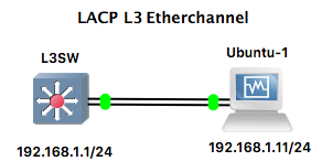
Link Aggregationのことを、Cisco用語では、Etherchannelと呼ぶようだ。GNS3内で、L2 Etherchannel、L3 EtherchannelそしてUbuntuとの接続をとりあげる。また、L3スイッチを利用している。
L2 Etherchannel
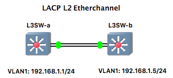
用いられる物理ポートはあるVLAN(ここではVLAN1)に属し、VLAN1にIPアドレスが割り当てられている。
設定
L3Switchの設定は下記となる。関連する部分のみ記載。当然のことながら、IPアドレスは、両方のSwitchで異なる。
interface Port-channel1
 switchport mode access
!
interface Ethernet0/0
 switchport mode access
 channel-group 1 mode active
!
interface Ethernet0/1
 switchport mode access
 channel-group 1 mode active

interface Vlan1
 ip address 192.168.1.1 255.255.255.0
設定状況は下記となる。
L3SW-a#show etherchannel summary
Flags:  D - down        P - bundled in port-channel
        I - stand-alone s - suspended
        H - Hot-standby (LACP only)
        R - Layer3      S - Layer2
        U - in use      N - not in use, no aggregation
        f - failed to allocate aggregator

        M - not in use, minimum links not met
        m - not in use, port not aggregated due to minimum links not met
        u - unsuitable for bundling
        w - waiting to be aggregated
        d - default port

        A - formed by Auto LAG


Number of channel-groups in use: 1
Number of aggregators:           1

Group  Port-channel  Protocol    Ports
------+-------------+-----------+-----------------------------------------------
1      Po1(SU)         LACP      Et0/0(P)    Et0/1(P)

L3SW-a#show etherchannel load-balance
EtherChannel Load-Balancing Configuration:
        src-dst-ip

EtherChannel Load-Balancing Addresses Used Per-Protocol:
Non-IP: Source XOR Destination MAC address
  IPv4: Source XOR Destination IP address
  IPv6: Source XOR Destination IP address

L3SW-a#show vlan

VLAN Name                             Status    Ports
---- -------------------------------- --------- -------------------------------
1    default                          active    Et0/2, Et0/3, Et1/0, Et1/1
                                                Et1/2, Et1/3, Po1
1002 fddi-default                     act/unsup
1003 token-ring-default               act/unsup
1004 fddinet-default                  act/unsup
1005 trnet-default                    act/unsup

VLAN Type  SAID       MTU   Parent RingNo BridgeNo Stp  BrdgMode Trans1 Trans2
---- ----- ---------- ----- ------ ------ -------- ---- -------- ------ ------
1    enet  100001     1500  -      -      -        -    -        0      0
1002 fddi  101002     1500  -      -      -        -    -        0      0
1003 tr    101003     1500  -      -      -        -    -        0      0
1004 fdnet 101004     1500  -      -      -        ieee -        0      0
1005 trnet 101005     1500  -      -      -        ibm  -        0      0

Remote SPAN VLANs
------------------------------------------------------------------------------


Primary Secondary Type              Ports
------- --------- ----------------- ------------------------------------------
「Po1(SU)」の”S”は、Layer2を意味する。
検証
pingの結果をWiresharkで取得。
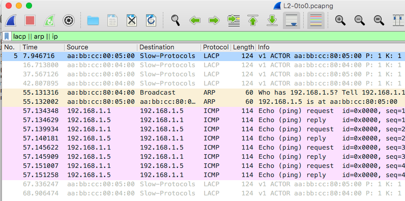
ARPもICMPも、片方の回線(Ethernet0/0)で行われていた。
L3 Etherchannel
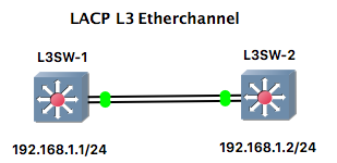
用いられるポートはL3ポートとなる。
設定
L3Switchの設定は下記となる。関連する部分のみ記載。
interface Port-channel1
 no switchport
 ip address 192.168.1.1 255.255.255.0
!
interface Ethernet0/0
 no switchport
 no ip address
 duplex auto
 channel-group 1 mode active
!
interface Ethernet0/1
 no switchport
 no ip address
 duplex auto
 channel-group 1 mode active
設定状況は下記となる。
L3SW-1#show etherchannel summary
Flags:  D - down        P - bundled in port-channel
        I - stand-alone s - suspended
        H - Hot-standby (LACP only)
        R - Layer3      S - Layer2
        U - in use      N - not in use, no aggregation
        f - failed to allocate aggregator

        M - not in use, minimum links not met
        m - not in use, port not aggregated due to minimum links not met
        u - unsuitable for bundling
        w - waiting to be aggregated
        d - default port

        A - formed by Auto LAG


Number of channel-groups in use: 1
Number of aggregators:           1

Group  Port-channel  Protocol    Ports
------+-------------+-----------+-----------------------------------------------
1      Po1(RU)         LACP      Et0/0(P)    Et0/1(P)

L3SW-1#show etherchannel load-balance
EtherChannel Load-Balancing Configuration:
        src-dst-ip

EtherChannel Load-Balancing Addresses Used Per-Protocol:
Non-IP: Source XOR Destination MAC address
  IPv4: Source XOR Destination IP address
  IPv6: Source XOR Destination IP address

L3SW-1#show int status

Port      Name               Status       Vlan       Duplex  Speed Type
Et0/0                        connected    routed       auto   auto unknown
Et0/1                        connected    routed       auto   auto unknown
Et0/2                        connected    1            auto   auto unknown
Et0/3                        connected    1            auto   auto unknown
Et1/0                        connected    1            auto   auto unknown
Et1/1                        connected    1            auto   auto unknown
Et1/2                        connected    1            auto   auto unknown
Et1/3                        connected    1            auto   auto unknown
Po1                          connected    routed       auto   auto
「Po1(RU)」の”R”は、Layer3を意味する。
検証
同じくpingの結果をWiresharkで取得。
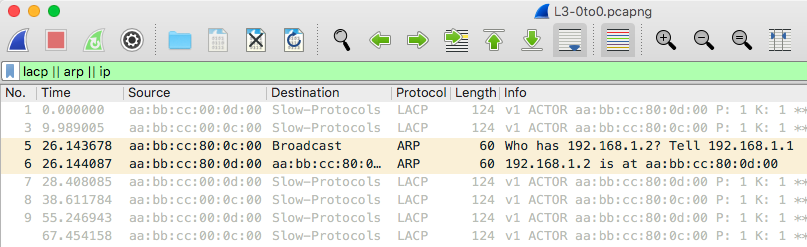
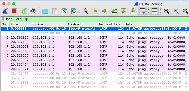
Layer2とは異なり、ARPはEthernet0/0を用いて、ICMPはEthernet0/1を用いて行われていた。理由は不明。
Ubuntu
設定
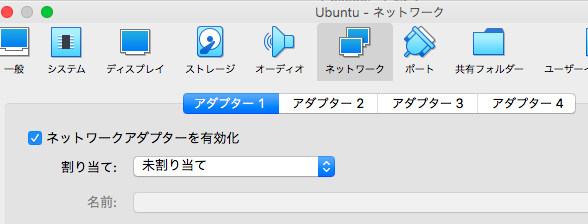
まずVirtualBoxのネットワーク設定であるが、アダプター1およびアダプター2のネットワークを有効化し、「未割り当て」としておく。
次にUbuntuでのLACP設定。関連する記事は多数見つかる。例えば、次のもの。
- Ubuntu 20.04 LTSでリンクアグリゲーション(LACP)を組んでみた
-
Ubuntu 20.04にリンクアグリゲーションを設定する
各種情報をもとに、下記設定を実施。
# Let NetworkManager manage all devices on this system
network:
  version: 2
  renderer: NetworkManager
#
  ethernets:
    enp0s3:
      dhcp4: no
    enp0s8:
      dhcp4: no
  bonds:
    bnd0:
      interfaces: [enp0s3, enp0s8]
      addresses: [192.168.1.11/24]
      gateway4: 192.168.1.1
      parameters:
        mode: 802.3ad
        lacp-rate: fast
        transmit-hash-policy: layer3+4
        mii-monitor-interval: 1
設定の反映。
$ sudo netplan apply
設定状況は下記のとおり。
$ ip link
1: lo: <LOOPBACK,UP,LOWER_UP> mtu 65536 qdisc noqueue state UNKNOWN mode DEFAULT group default qlen 1000
    link/loopback 00:00:00:00:00:00 brd 00:00:00:00:00:00
2: enp0s3: <BROADCAST,MULTICAST,SLAVE,UP,LOWER_UP> mtu 1500 qdisc fq_codel master bnd0 state UP mode DEFAULT group default qlen 1000
    link/ether 08:00:27:fd:86:08 brd ff:ff:ff:ff:ff:ff
3: enp0s8: <BROADCAST,MULTICAST,SLAVE,UP,LOWER_UP> mtu 1500 qdisc fq_codel master bnd0 state UP mode DEFAULT group default qlen 1000
    link/ether 08:00:27:fd:86:08 brd ff:ff:ff:ff:ff:ff
4: bnd0: <BROADCAST,MULTICAST,MASTER,UP,LOWER_UP> mtu 1500 qdisc noqueue state UP mode DEFAULT group default qlen 1000
    link/ether 08:00:27:fd:86:08 brd ff:ff:ff:ff:ff:ff
$
$ ip address
1: lo: <LOOPBACK,UP,LOWER_UP> mtu 65536 qdisc noqueue state UNKNOWN group default qlen 1000
    link/loopback 00:00:00:00:00:00 brd 00:00:00:00:00:00
    inet 127.0.0.1/8 scope host lo
       valid_lft forever preferred_lft forever
    inet6 ::1/128 scope host
       valid_lft forever preferred_lft forever
2: enp0s3: <BROADCAST,MULTICAST,SLAVE,UP,LOWER_UP> mtu 1500 qdisc fq_codel master bnd0 state UP group default qlen 1000
    link/ether 08:00:27:fd:86:08 brd ff:ff:ff:ff:ff:ff
3: enp0s8: <BROADCAST,MULTICAST,SLAVE,UP,LOWER_UP> mtu 1500 qdisc fq_codel master bnd0 state UP group default qlen 1000
    link/ether 08:00:27:fd:86:08 brd ff:ff:ff:ff:ff:ff
4: bnd0: <BROADCAST,MULTICAST,MASTER,UP,LOWER_UP> mtu 1500 qdisc noqueue state UP group default qlen 1000
    link/ether 08:00:27:fd:86:08 brd ff:ff:ff:ff:ff:ff
    inet 192.168.1.11/24 brd 192.168.1.255 scope global noprefixroute bnd0
       valid_lft forever preferred_lft forever
    inet6 fe80::a00:27ff:fefd:8608/64 scope link
       valid_lft forever preferred_lft forever
L3スイッチの設定は、L3 Etherchannelのときと同じ。
検証
同じくpingの結果をWiresharkで取得(Ubuntuにて)。
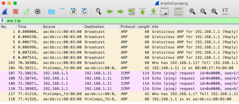

ARPおよびICMP requestはEthernet0/0(enp0s3)を用いて、ICMP replyはEthernet0/1(enp0s8)を用いて行われていた。こちらも理由は不明ではあるが、差があるのは興味深い。
L3スイッチ側L2Etherchannel - Ubuntu

設定
L3スイッチの設定はL2Etherchannelと同じ、Ubuntu側は一つ前のUbuntuの設定と同じである。
検証
同じくpingの結果をWiresharkで取得したが、一つ前と同じく、ARPおよびICMP requestはEthernet0/0(enp0s3)を用いて、ICMP replyはEthernet0/1(enp0s8)を用いて行われていた。
おまけ
今回、GNS3でIOUを利用したが、特定versionのIOUでは、LACPは正しく機能しないことがあるようだ(それらしき記事も見つかった)。