なんかもう間に合うか怪しいのですが、LINE Things Mini Award用に作ろうと思ってるやつがあります。
それはDCモーター(TAMIYA)一つとサーボモーター1つと、連続回転サーボを1つ使う予定のやつ。
でもってESP32、もしくはarduino+BLEモジュールを2組つかいたい。
で、調べてみるとこういったモーターを使うにはモータードライバーとかいうやつがあるといいらしい。
モータードライバとは、モーターを駆動・制御する装置のこと。モーターに流す電流量、方向、タイミングなどを制御するもので、DCモーター、ACモーター、ステッピングモーターなどモーターの種類により駆動方法・回路が異なる。
例えばDCモーターの場合には、電流の向きを切換えることでモーターの回転方向をコントロールするHブリッジ回路を組み、リニア方式で電流制御をしたり、PWM制御をしたりして回転数の制御を行う。
そんわけでDCモーター用のやつとサーボモーター複数制御用のを購入してみました。
本日の材料
- HiLetgo PCA9685 16チャンネル 12-ビット PWM Servo モーター ドライバー IIC モジュール Arduinoに対応 ロボット
- Calloy L298N モジュール デュアルHブリッジ DCステップ モーター ドライバー コントローラー ボード Arduinoと互換 2個
- Goolsky 1セット アクリル ロボット アーム クランプ クロー マウント キット 9Gサーボ付き Arduino DIYロボット用 キット
- DiyStudio Bluetooth開発ボード WiFi 開発ボード CP2102 ESP-32 ESP-32S開発ボード2.4GHzデュアルモードWiFi + BluetoothアンテナモジュールAP、STA、およびAP + STA 3モード
- KKHMF UNO R3開発ボード USBケーブル付属 Arduinoと互換
- Feetech FS90R マイクロサーボ 360度連続回転サーボ 6V 9G 車輪付き 2点入り RCサーボ 900us-2100us [並行輸入品]
- SG90-HV 360度旋回タイプ デジタル・マイクロサーボ
- AO-1001:FA-130ノーマルモーター
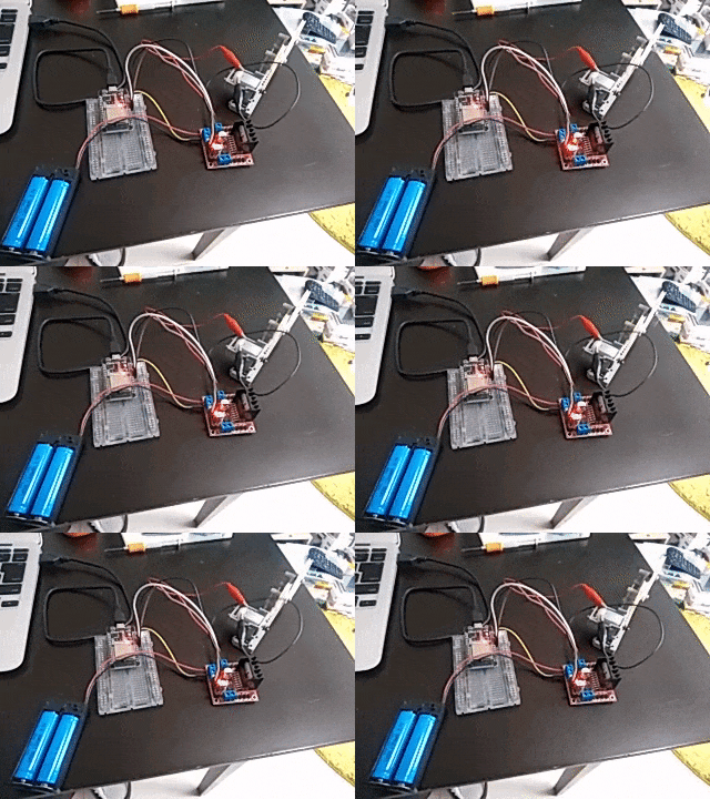
L298Nとタミヤモーター
これは単純。L298Nにモーターを繋いで正回転と逆回転と停止ができればOKです。
やべぇ。。部屋汚いのバレたわ。。
ちなみにブン回してるのはタミヤ 楽しい工作シリーズ No.121 プーリーユニットセット です。
ESP32のGPIO14をENAに、GPIO26をIN2に、GPIO27をIN1につないでます。あとGNDも繋いでる。
そしてL298NのOUT1とOUT2をモーターの端子に繋げています。
あ、電池もL298N用に別電源(電池ボックス)つないでます。
arduinoのソースはこんな感じ。ちょっと電圧でかいの使ってるけど、たぶん3Vでも問題ないと思う。
/*********
  Rui Santos
  Complete project details at http://randomnerdtutorials.com
*********/

// Motor A
int motor1Pin1 = 27;
int motor1Pin2 = 26;
int enable1Pin = 14;

// Setting PWM properties
const int freq = 30000;
const int pwmChannel = 0;
const int resolution = 8;
int dutyCycle = 200;

void setup() {
  // sets the pins as outputs:
  pinMode(motor1Pin1, OUTPUT);
  pinMode(motor1Pin2, OUTPUT);
  pinMode(enable1Pin, OUTPUT);

  // configure LED PWM functionalitites
  ledcSetup(pwmChannel, freq, resolution);

  // attach the channel to the GPIO to be controlled
  ledcAttachPin(enable1Pin, pwmChannel);

  Serial.begin(115200);

  // testing
  Serial.print("Testing DC Motor...");
}

void loop() {
  // Move the DC motor forward at maximum speed
  Serial.println("Moving Forward");
  digitalWrite(motor1Pin1, LOW);
  digitalWrite(motor1Pin2, HIGH);
  delay(2000);

  // Stop the DC motor
  Serial.println("Motor stopped");
  digitalWrite(motor1Pin1, LOW);
  digitalWrite(motor1Pin2, LOW);
  delay(1000);

  // Move DC motor backwards at maximum speed
  Serial.println("Moving Backwards");
  digitalWrite(motor1Pin1, HIGH);
  digitalWrite(motor1Pin2, LOW);
  delay(2000);

  // Stop the DC motor
  Serial.println("Motor stopped");
  digitalWrite(motor1Pin1, LOW);
  digitalWrite(motor1Pin2, LOW);
  delay(1000);

  // Move DC motor forward with increasing speed
  digitalWrite(motor1Pin1, HIGH);
  digitalWrite(motor1Pin2, LOW);
  while (dutyCycle <= 255){
    ledcWrite(pwmChannel, dutyCycle);
    Serial.print("Forward with duty cycle: ");
    Serial.println(dutyCycle);
    dutyCycle = dutyCycle + 5;
    delay(500);
  }
  dutyCycle = 200;
}
コメントにもありますが、https://randomnerdtutorials.com/ さんのソースがほぼそのままだったと思います。
digitalWrite(motor1Pin1, LOW); みたいなとこでオンオフしてますが、どちらか片方をHIGHにするとどっちかに回転する。両方LOWにすると止まる。
最終的にはこれをBLE経由で操作したい。
PCA9685とサーボモーター2種
こんどはサーボーモーター。なんかいつもちゃんと動かなくて苦戦するんですけどねー、サーボちゃん。
今回もなかなかうまくいかなくて、ESP32を一個壊してしまった。。
仕方ないのでarduino互換機でやってます。
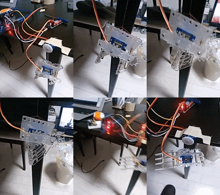
とある事情でクレーンアームをサーボで動かしています。そしてそのアームを連続回転サーボで上げ下げする。だいぶいまいちなんだけどギリギリ動いた。
ソースはこんな感じです。
/***************************************************
  This is an example for our Adafruit 16-channel PWM & Servo driver
  Servo test - this will drive 8 servos, one after the other on the
  first 8 pins of the PCA9685

  Pick one up today in the adafruit shop!
  ------> http://www.adafruit.com/products/815

  These drivers use I2C to communicate, 2 pins are required to
  interface.

  Adafruit invests time and resources providing this open source code,
  please support Adafruit and open-source hardware by purchasing
  products from Adafruit!

  Written by Limor Fried/Ladyada for Adafruit Industries.
  BSD license, all text above must be included in any redistribution
 ****************************************************/

# include <Wire.h>
# include <Adafruit_PWMServoDriver.h>

// called this way, it uses the default address 0x40
Adafruit_PWMServoDriver pwm = Adafruit_PWMServoDriver();
// you can also call it with a different address you want
//Adafruit_PWMServoDriver pwm = Adafruit_PWMServoDriver(0x41);
// you can also call it with a different address and I2C interface
//Adafruit_PWMServoDriver pwm = Adafruit_PWMServoDriver(&Wire, 0x40);

// Depending on your servo make, the pulse width min and max may vary, you
// want these to be as small/large as possible without hitting the hard stop
// for max range. You'll have to tweak them as necessary to match the servos you
// have!
# define SERVOMIN  150 // this is the 'minimum' pulse length count (out of 4096)
# define SERVOMAX  600 // this is the 'maximum' pulse length count (out of 4096)

void setup() {
  Serial.begin(9600);
  Serial.println("Servo test!");

  pwm.begin();

  pwm.setPWMFreq(60);  // Analog servos run at ~60 Hz updates

  delay(10);
}

// you can use this function if you'd like to set the pulse length in seconds
// e.g. setServoPulse(0, 0.001) is a ~1 millisecond pulse width. its not precise!
void setServoPulse(uint8_t n, double pulse) {
  double pulselength;

  pulselength = 1000000;   // 1,000,000 us per second
  pulselength /= 60;   // 60 Hz
  Serial.print(pulselength); Serial.println(" us per period");
  pulselength /= 4096;  // 12 bits of resolution
  Serial.print(pulselength); Serial.println(" us per bit");
  pulse *= 1000000;  // convert to us
  pulse /= pulselength;
  Serial.println(pulse);
  pwm.setPWM(n, 0, pulse);
}

void loop() {

  //アームを下げる
  pwm.setPWM(1, 0, 300);
  delay(2000);
  pwm.setPWM(1, 0, 0);
  delay(5000);


  // アームを閉じる
  for (uint16_t pulselen = SERVOMAX; pulselen > SERVOMIN; pulselen--) {
    pwm.setPWM(0, 0, pulselen);
  }

  delay(5000);

  //アームをあげる
  pwm.setPWM(1, 0, 400);
  delay(2000);
  pwm.setPWM(1, 0, 0);
  delay(5000);

  // アームを開く
  for (uint16_t pulselen = SERVOMIN; pulselen < SERVOMAX; pulselen++) {
    pwm.setPWM(0, 0, pulselen);
  }

  delay(30000);
}
ほぼ、adafruiteのAdafruit_PWMServoDriverサンプルスケッチのままですね。
PCA9685のサーボ0のとこにアーム用のサーボを。サーボ1のとこに連続回転サーボを繋いでます。
連続回転サーボはどこかのパルスで回転が反転するんだけど、いじりながらやってたら300と400の数値でちょうど反転しました。モーターについてるネジで調整もできますけどね。
電源はUSBの別電源をV++に入れてます。arduinoとはSCLとSDAをそのままつなぎつつ、VCCに5V、GNDはGNDで繋いでますね。ESP32だとGPIO21と22をSDA、SCLにつなぐといいらしい。
そんなわけでいちおう動いたって所まで。
まだ動き怪しいんですけども。
あとはBLE経由での操作と、超音波モジュールで距離測るのをやらないと。

