2リンクマニピュレータ
はじめに
本記事は制御工学 Advent Calendar 2018 22日目になります。
今年は皆さんしっかりと準備をされた記事が多いようでこのあたりで
一度投稿のハードルを下げにかかりたいと思います。
今回はロボットアームのうち水平2リンクのアーム(2リンクマニピュレータ)を
実際に動作させて、マニピュレータの軌道追従制御を実践しました。
ハードウェア構成
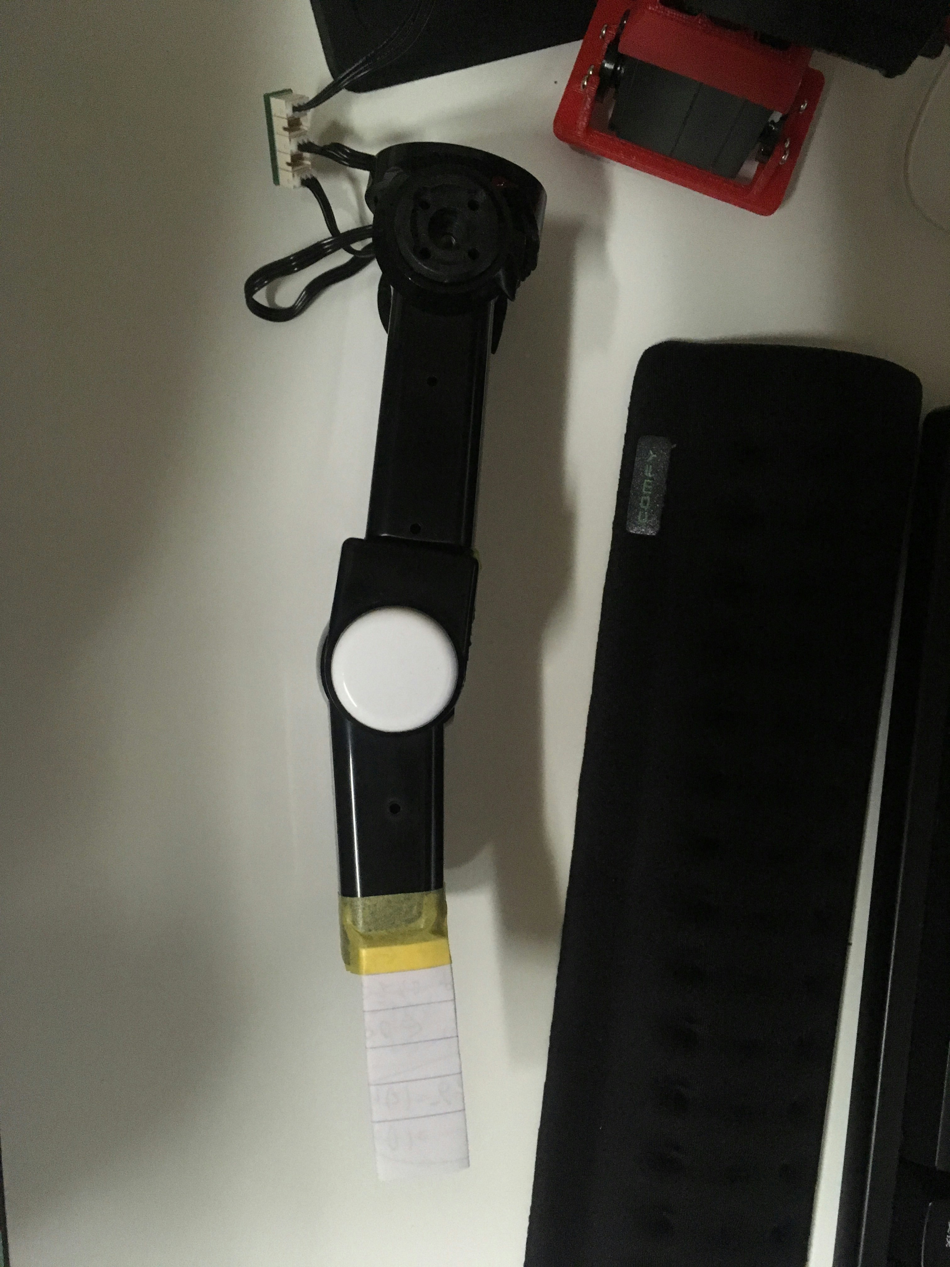
使用したロボットアームは図のとおりです。某市販ロボットの腕を改造して
使用しています。サーボモータにはKRS-3204を使用しています。
近藤科学のサーボモータはシリアル通信によって現在の位置も得ることができるため、
PWMでサーボを使用する場合に比べて色々と遊ぶことができます。
モデル設定
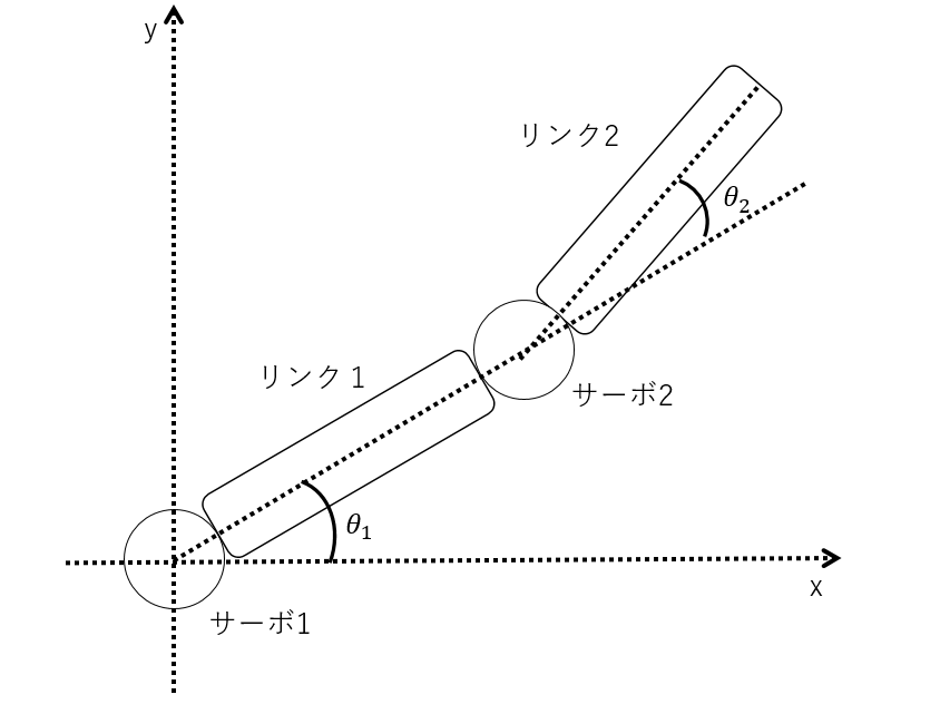
2リンクマニピュレータを図のように設定しました。
ここで今後の解説のために、固定したサーボモータを
サーボ1,サーボ1に接続されたアームをリンク1とします。また、リンク1の先端に
固定したサーボモータをサーボ2、アーム先端のリンクをリンク2とします。
順運動学
前図のようにモデルを定義したので、まずは順運運動学から求めてみます。
順運動学は、今回であればサーボ1,2の角度を与えるとリンク2の先端位置が
わかる式となります。
[]($$x_1=L_1 cos\theta_1$$)
まず、リンク1の先端の位置を求めます。三角関数を用いて次のようになります。
x=L_1 cos\theta_1 + L_2cos(\theta_1+\theta_2)\\
y=L_1 sin\theta_1 + L_2sin(\theta_1+\theta_2)
以上で今回制御したいリンク2の先端位置がわかります。
順運動学による式は制御には直接用いませんが、MATLAB等で
シミュレーションを行う時に必要となったりします。
逆運動学(解析解を利用)
逆運動学では、リンク2の先端の位置を指定して、サーボ1,2の角度を得ます。
まず、サーボ1の角度$theta_1$について求めます。式変形の過程を示します。
移項します。
x-L_1 cos\theta_1=L_2cos(\theta_1+\theta_2)\\
y-L_1 sin\theta_1=L_2sin(\theta_1+\theta_2)
両辺を2乗します。
x^2-2xL_1 cos\theta_1+L_1^2cos^2\theta=L_2^2cos^2(\theta_1+\theta_2)\\
y^2-2yL_1 sin\theta_1+L_1^2sin^2\theta=L_2^2sin^2(\theta_1+\theta_2)
2つの式を足し合わせて整理します。
x^2+y^2-2xL_1 cos\theta_1-2yL_1 sin\theta_1+L_1^2(cos^2\theta+sin^2\theta)\\
=L_2^2(cos^2(\theta_1+\theta_2)+sin^2(\theta_1+\theta_2))\\
\therefore
x^2+y^2-2L_1 (xcos\theta_1+ ysin\theta_1) +L_1^2=L_2^2
$cos\theta_1+ sin\theta_1$について整理します。
xcos\theta_1+ ysin\theta_1 =\frac{x^2+y^2+L_1^2-L_2^2}{2L_1}
左辺について三角関数の合成で$cos$にまとめます。
\sqrt{x^2+y^2}cos(\theta_1+\gamma)=\frac{x^2+y^2+L_1^2-L_2^2}{2L_1}\\
(tan\gamma = \frac{y}{x})
あとは逆余弦を使って$theta_1$について解きます。
\theta_1=-\gamma\pm acos(\frac{x^2+y^2+L_1^2-L_2^2}{2L_1\sqrt{x^2+y^2}})\\
(tan\gamma = \frac{y}{x})
以上で$theta_1$については解けました。次に$theta_2$について解きます。
同様にまず、順運動学の式を基に移項します。
x-L_1 cos\theta_1=L_2cos(\theta_1+\theta_2)\\
y-L_1 sin\theta_1=L_2sin(\theta_1+\theta_2)
ここで、2つ目の式を1つ目の式で割ります。
\frac{y-L_1 sin\theta_1}{x-L_1 cos\theta_1}
=\frac{L_2sin(\theta_1+\theta_2)}{L_2cos(\theta_1+\theta_2)}\\
\therefore
\frac{y-L_1 sin\theta_1}{x-L_1 cos\theta_1}=tan(\theta_1+\theta_2)
あとは逆関数で求めておしまいです。
\theta_1+\theta_2=atan(\frac{y-L_1 sin\theta_1}{x-L_1 cos\theta_1})\\
\therefore
\theta_2=-\theta_1+atan(\frac{y-L_1 sin\theta_1}{x-L_1 cos\theta_1})
以上をまとめると,逆運動学を解析的にもとめた結果の一例は次のようになります。
(求め方によって他の表記になる場合もあるようです)
\theta_1=-\gamma\pm acos(\frac{x^2+y^2+L_1^2-L_2^2}{2L_1\sqrt{x^2+y^2}})\\
\theta_2=-\theta_1+atan(\frac{y-L_1 sin\theta_1}{x-L_1 cos\theta_1})\\
(tan\gamma = \frac{y}{x})
この時,リンク1に関しては2つの角度が計算されますが,ハードウェアの諸事情から
マイナス側の角度を採用しました.そのため,逆運動学の解析回として次式を利用しました。
\theta_1=-\gamma- acos(\frac{x^2+y^2+L_1^2-L_2^2}{2L_1\sqrt{x^2+y^2}})\\
\theta_2=-\theta_1+atan(\frac{y-L_1 sin\theta_1}{x-L_1 cos\theta_1})\\
(tan\gamma = \frac{y}{x})
逆運動学(ヤコビ行列を利用)
今回は2リンクマニピュレータのため解析的にも解が求まります。しかし、自由度が
増加するにつれ解析的に逆運動学の式を求められないことがあります。そこで、
数値計算で解いていこうという方法もあります。
まず、順運動学で出てきた式の両辺を時間で微分します.
\dot x=-(L_1 sin\theta_1 + L_2 sin(\theta_1 + \theta_2))\dot \theta_1
  -L_2 sin(\theta_1 + \theta_2)\\
\dot y=(L_1 cos\theta_1 +L_2 cos(\theta_1 + \theta_2))\dot \theta_1
  +L_2 cos(\theta_1 + \theta_2)
次に,これを行列式を用いて表わすと,
\begin{pmatrix}
\dot x  \\ \dot y
\end{pmatrix}
=
\begin{pmatrix}
-L_1 sin\theta_1 - L_2 sin(\theta_1 + \theta_2) &
  -L_2 sin(\theta_1 + \theta_2)\\
L_1 cos\theta_1 +L_2 cos(\theta_1 + \theta_2) &
  +L_2 cos(\theta_1 + \theta_2)
\end{pmatrix}

\begin{pmatrix}
\dot \theta_1  \\ \dot \theta_2
\end{pmatrix}
となります.この2×2の行列部分をヤコビ行列と呼ぶそうです.
そこで,位置$p$,角度$\theta$,ヤコビ行列$J$について下記のように定義します.
p=\begin{pmatrix}
x  \\ y  \end{pmatrix}
\\
\theta = \begin{pmatrix}
\theta_1  \\\theta_2 \end{pmatrix}
\\
J=\begin{pmatrix}
-L_1 sin\theta_1 - L_2 sin(\theta_1 + \theta_2) &
  -L_2 sin(\theta_1 + \theta_2)\\
L_1 cos\theta_1 +L_2 cos(\theta_1 + \theta_2) &
  +L_2 cos(\theta_1 + \theta_2)
\end{pmatrix}
よって,
\dot p = J \dot \theta
となります.この式は角速度と直線速度の関係式ともみれます。
ここでヤコビ行列$J$が逆行列を持つと仮定すると、
\dot \theta = J^{-1} \dot p \\
\therefore \frac{\delta \theta}{\delta t} = J^{-1} \frac{\delta p }{\delta t}
となります.
このとき十分に小さい幅でこの計算を行うとすれば,
\delta \theta = J^{-1} \delta p
と考えられます.そこで,$\theta$の初期値さえ分かれば後は,目標となる位置から,
与えるべき角度を求められます.具体的な計算ステップは次のようになります.
サーボに与えるべき角度を得ます.
- $\theta$,$p$の初期値を設定する.
- 目標軌道を決める(直線,円etc...)
- 目標軌道を分割する.
- 現在位置を分割した次の点に動かす($\delta p_n$が計算される)
- 現在の角度を以下の式で更新する。$\theta_n = \theta_{n-1} + J_n^{-1} \delta p_n $
- 4,5ステップを繰り返す.
このようにして解析的な解が求められない場合でも逆運動学計算を行うことができます.
MATLABを用いたシミュレーション
実際にMATLABを用いてシミュレーションしてみます。
実際のコードもついでに掲載しておきます。
注意点として、atan関数とatan2関数では全く異なる結果が出ます。
atanでは引数が一つであり、象限が不明なため$\pm \pi/2$の範囲で返されるのに対して
atan2では引数が2つあり、ちゃんと象限が分かるため,$\pm \pi$の範囲で返してくれます。
この点に気付くのに少し時間がかかってしまいました.
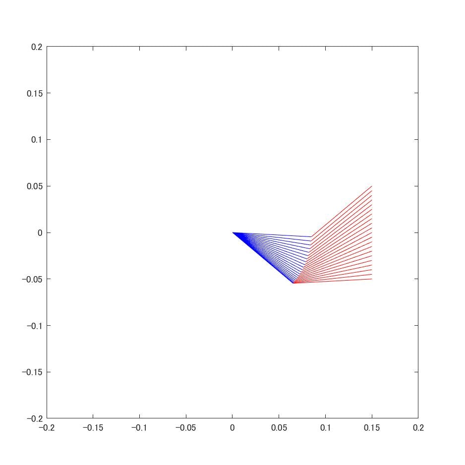
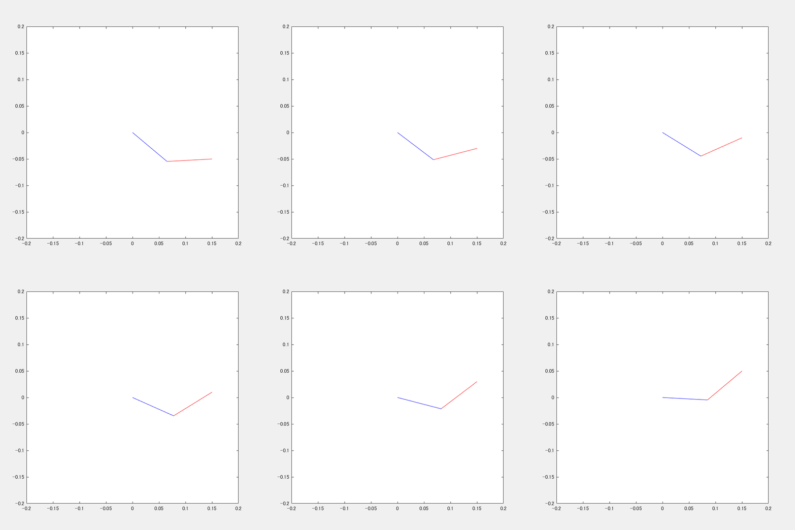
直線軌道への追従
直線起動への追従の様子です.綺麗に直線ぽく追従出来ています.
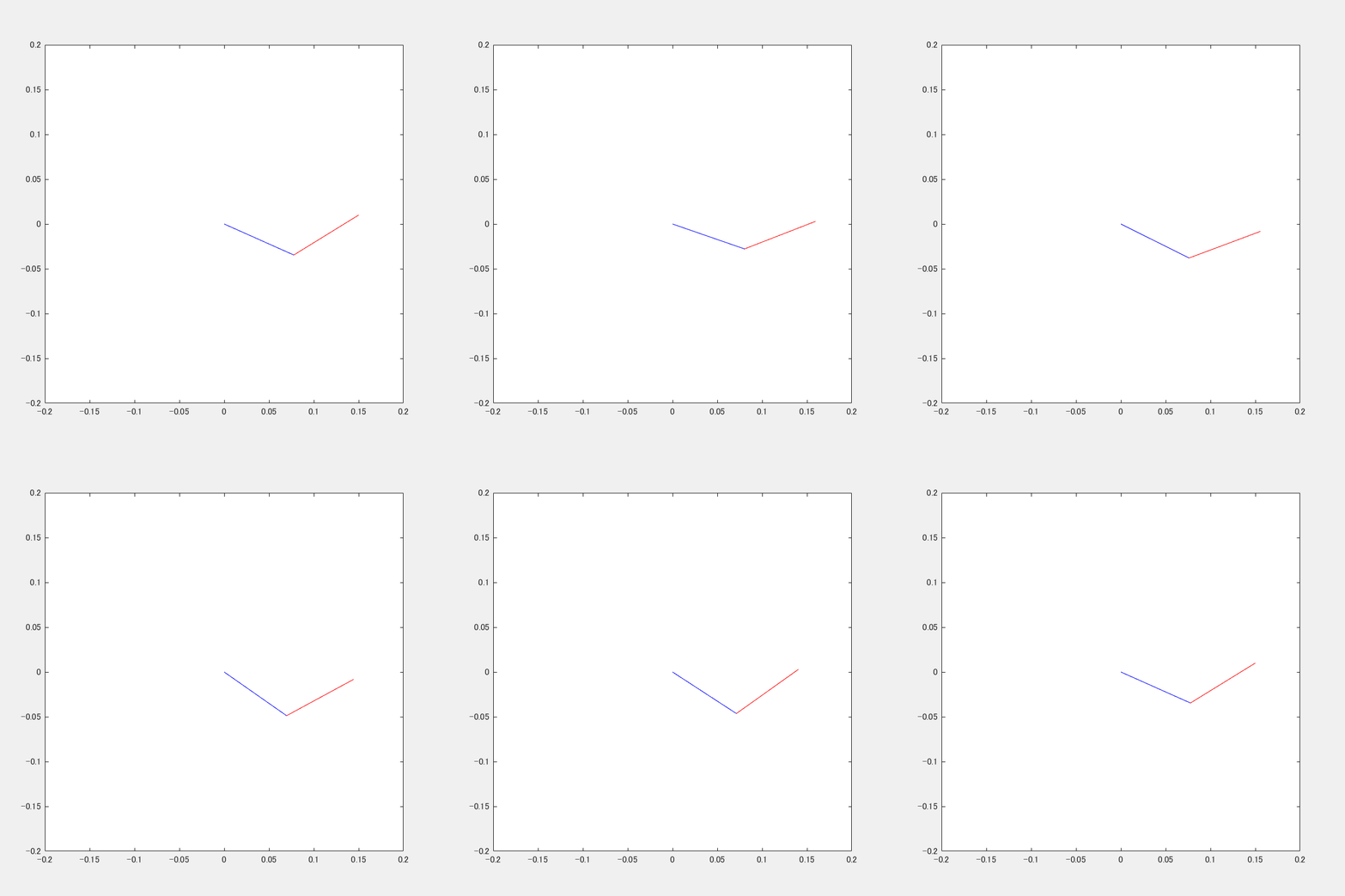
円軌道への追従
円線起動への追従の様子です.こちらもわかりづらいですが円を描けています.
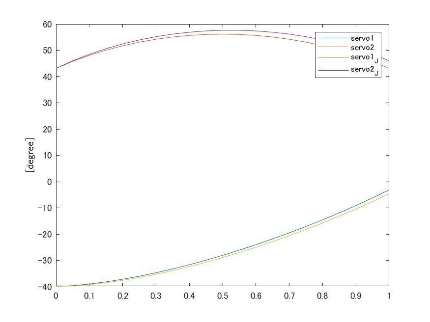
解析解を用いた場合とヤコビ行列を用いた場合の比較
アニメーションを用いて両者を比較出来ればよかったのですが、
残念ながら差異がほとんどなかったため、各サーボの角度のグラフを示します。
僅かにヤコビ行列を用いた場合の方が誤差がたまっていることが分かります。
これが分割点数の問題なのか、それ以外の何かなのか原因は調査できていません。
実機への適用
シミュレーションではうまくいくことはわかりましたので、ここはやはり
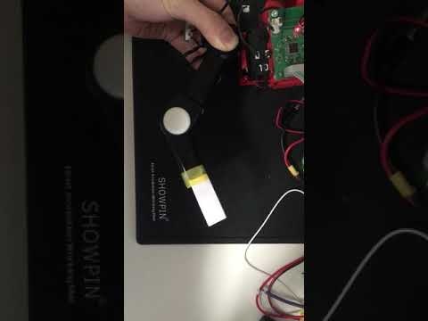
実際に実機に適用してみました.動画で伝わるかどうか微妙ですが,
非常にカクカクとした動作になっています.原因としては,指令間隔が長いことや
補間距離が長いこと,また目標値として位置のみを与え,内部のサーボ系では
その位置で速度が0になるにように制御されていること等が考えられます.
指令周期を高速化したりなんだりをすれば滑らかになるかもしれませなが,
Advent Calenderの都合上ここまででお許しください.
おわりに
うまくまとめ切れておらず、また他の投稿記事(Advent Calender 2018 制御工学)に
比べて薄い内容となってしまいましたことお詫び申し上げます.
参考コード
MATLAB
function arm_inv_arm_angle
format compact;
clear all;
close all;

state_servo1=struct('angle',0,'length',0.085);
state_servo2=struct('angle',0,'length',0.085);

f = figure('Position',[1300,400,600,600]);
ax = axes('Parent',f,'position',[0.1 0.1  0.8 0.8]);
h=plot(0,0);hold on;pbaspect([1 1 1]);  %表示アスペクト比を1:1
axis([-0.2,0.2,-0.2,0.2]);

% 角度で入力
% state_servo1.angle=deg2rad(-22.9094);
% state_servo2.angle=deg2rad(-68.5216);
% plot_arm(f,state_servo1,state_servo2)

% 逆運動学で計算してみる
% % ref=gen_servo_angle(0.2, 0.0)
% state_servo1.angle =ref(1);
% state_servo2.angle =ref(2);
% plot_arm(f,state_servo1,state_servo2)

% 逆運動学で直線を出す
y_ref=-0.05:0.005:0.05;
x_ref=ones(1,length(y_ref)).*0.15;

% 逆運動学で円を出す
% th=linspace(0,2*pi,100);
% R=0.01;
% x_ref=sin(th).*R +0.15;
% y_ref=cos(th).*R +0;

% アニメーション実行
t=0:Ts:(length(x_ref)-1)*Ts;
data_servo1_anlge=0;data_servo2_anlge=0;
data_servo1_anlge_J=0;data_servo2_anlge_J=0;
JacobianTheta=0;last_p=0;  %ヤコビ行列で計算するとき
for i=1:length(x_ref)
%     解析解を用いた場合
    ref=gen_servo_angle(x_ref(i),y_ref(i));

%     ヤコビ行列を用いた場合
    if i==1
        last_p=[x_ref(1);y_ref(1)];
        JacobianTheta=[ref(1);ref(2)];
    else
        J=JacobianMatrix(state_servo1.angle,state_servo2.angle,...
            state_servo1.length,state_servo2.length);
        delta_p=[x_ref(i);y_ref(i)]-last_p;
        last_p = [x_ref(i);y_ref(i)];
        JacobianTheta = JacobianTheta + J\ delta_p;
    end

%     ヤコビ行列でやる場合は下のコメントアウトを解除
%     ref = JacobianTheta';

    state_servo1.angle =ref(1);
    state_servo2.angle =ref(2);

    data_servo1_anlge(i)=ref(1);
    data_servo2_anlge(i)=ref(2);
    data_servo1_anlge_J(i)=JacobianTheta(1);
    data_servo2_anlge_J(i)=JacobianTheta(2);

    plot_arm(f,state_servo1,state_servo2)
    pause(20/1000);
end

% 角度情報を見てみる
figure();
plot(t,rad2deg(data_servo1_anlge),t,rad2deg(data_servo2_anlge),...
    t,rad2deg(data_servo1_anlge_J),t,rad2deg(data_servo2_anlge_J));
legend('servo1','servo2','servo1_J','servo2_J')

% ヤコビ行列を求める
function J=JacobianMatrix(theta1,theta2,L1,L2)
    J=[-L1 * sin(theta1)-L2*sin(theta1+theta2) ,-L2*sin(theta1+theta2);
        L1*cos(theta1)+L2*cos(theta1+theta2), L2*cos(theta1+theta2)];
end

function plot_arm(f,servo1,servo2)
figure(f);
cla; %この行をコメントアウトするとアームのステップごとの位置が見れる
% arm 1st
plot([0.0 , servo1.length * cos(servo1.angle)],...
    [0.0 ,servo1.length * sin(servo1.angle)],'b');
% arm 2nd
plot([servo1.length * cos(servo1.angle) ,...
        servo1.length * cos(servo1.angle)...
        + servo2.length * cos(servo1.angle + servo2.angle)],...
    [servo1.length * sin(servo1.angle) ,...
        servo1.length * sin(servo1.angle)...
        + servo2.length * sin(servo1.angle + servo2.angle)],'r');
end

function theta=gen_servo_angle(x,y)
    L1=state_servo1.length;
    L2=state_servo2.length;

%     ここで+-の候補が出てくる.
    theta(1)=atan2(y,x)...
        -acos( (x^2 + y^2 + L1^2 - L2^2)/(2*L1 * sqrt(x^2+y^2)) );
%         +acos( (x^2 + y^2 + L1^2 - L2^2)/(2*L1 * sqrt(x^2+y^2)) );
    theta(2)=-theta(1) + atan2((y-L1*sin(theta(1))) , (x-L1*cos(theta(1))));
end

end
参考文献
[1]http://www-bs.ss.oka-pu.ac.jp/inoue/class/robot/ロボット工学.pdf
[2]早川恭弘,櫟 弘明,矢野順彦 機械系教科書シリーズ22 ロボット工学
