はじめに
QiitaなどでM5Stackの画面を投稿するのに、画面キャプチャーが欲しいですよね。でも残念ながらM5Stackの標準機能にはないようです。私が、仕事で関わっているRecord Meetingという自動議事メモ作成サービスでは、独自のスマートスピーカーのUIとしてM5Stackを使っていて、色んな場面でキャプチャーが必要なんですが、これまで画面をスマホ等で撮影して対応しており、きれいに撮影するのに苦労していました。
実は、M5Stackのライブラリの中にスクリーンキャプチャを行うサンプルがあるんですが、そのままでは動作しませんでした。https://github.com/m5stack/M5Stack/blob/master/examples/Advanced/Display/TFT_Screen_Capture/TFT_Screen_Capture.ino
これは、M5Stackが取り込んでいるTFT_eSPIのサンプルがそのままコピーされたもので、取り込まれているTFT_eSPIが古いため手を入れないといけませんでした。(検索してもまったく情報がないので、誰も使っていないのかもしれません)
元のサンプルはシリアル接続やProcessingなどを使うもので単体では使えず少し不便でした。そこで、キャプチャーするとM5StackのmicroSDカードに保存するようなツールを作ってみました。PNGやBMPなどの画像形式を作成する良いライブラリがなかったので、BMPフォーマットを自分で作成するようにしています。
実装方法
プロジェクトのlibフォルダー下にTFT_eSPIを配置します。肝心なのは、こちらのUser_Setup.hをM5Stack用に設定するところです。
//                            USER DEFINED SETTINGS
//   Set driver type, fonts to be loaded, pins used and SPI control method etc
//
//   See the User_Setup_Select.h file if you wish to be able to define multiple
//   setups and then easily select which setup file is used by the compiler.
//
//   If this file is edited correctly then all the library example sketches should
//   run without the need to make any more changes for a particular hardware setup!
//   Note that some sketches are designed for a particular TFT pixel width/height


// ##################################################################################
//
// Section 1. Call up the right driver file and any options for it
//
// ##################################################################################

// Only define one driver, the other ones must be commented out
# define ILI9341_DRIVER
//#define ST7735_DRIVER      // Define additional parameters below for this display
//#define ILI9163_DRIVER     // Define additional parameters below for this display
//#define S6D02A1_DRIVER
//#define RPI_ILI9486_DRIVER // 20MHz maximum SPI
//#define HX8357D_DRIVER
//#define ILI9481_DRIVER
//#define ILI9486_DRIVER
//#define ILI9488_DRIVER     // WARNING: Do not connect ILI9488 display SDO to MISO if other devices share the SPI bus (TFT SDO does NOT tristate when CS is high)
//#define ST7789_DRIVER      // Full configuration option, define additional parameters below for this display
//#define ST7789_2_DRIVER    // Minimal configuration option, define additional parameters below for this display
//#define R61581_DRIVER
//#define RM68140_DRIVER

// Some displays support SPI reads via the MISO pin, other displays have a single
// bi-directional SDA pin and the library will try to read this via the MOSI line.
// To use the SDA line for reading data from the TFT uncomment the following line:

# define TFT_SDA_READ      // This option is for ESP32 ONLY, tested with ST7789 display only

// For ST7789 and ILI9341 ONLY, define the colour order IF the blue and red are swapped on your display
// Try ONE option at a time to find the correct colour order for your display

//  #define TFT_RGB_ORDER TFT_RGB  // Colour order Red-Green-Blue
# define TFT_RGB_ORDER TFT_BGR  // Colour order Blue-Green-Red

// For M5Stack ESP32 module with integrated ILI9341 display ONLY, remove // in line below

# define M5STACK

// For ST7789, ST7735 and ILI9163 ONLY, define the pixel width and height in portrait orientation
// #define TFT_WIDTH  80
// #define TFT_WIDTH  128
// #define TFT_WIDTH  240 // ST7789 240 x 240 and 240 x 320
// #define TFT_HEIGHT 160
// #define TFT_HEIGHT 128
// #define TFT_HEIGHT 240 // ST7789 240 x 240
// #define TFT_HEIGHT 320 // ST7789 240 x 320

// For ST7735 ONLY, define the type of display, originally this was based on the
// colour of the tab on the screen protector film but this is not always true, so try
// out the different options below if the screen does not display graphics correctly,
// e.g. colours wrong, mirror images, or tray pixels at the edges.
// Comment out ALL BUT ONE of these options for a ST7735 display driver, save this
// this User_Setup file, then rebuild and upload the sketch to the board again:

// #define ST7735_INITB
// #define ST7735_GREENTAB
// #define ST7735_GREENTAB2
// #define ST7735_GREENTAB3
// #define ST7735_GREENTAB128    // For 128 x 128 display
// #define ST7735_GREENTAB160x80 // For 160 x 80 display (BGR, inverted, 26 offset)
// #define ST7735_REDTAB
// #define ST7735_BLACKTAB
// #define ST7735_REDTAB160x80   // For 160 x 80 display with 24 pixel offset

// If colours are inverted (white shows as black) then uncomment one of the next
// 2 lines try both options, one of the options should correct the inversion.

# define TFT_INVERSION_ON
// #define TFT_INVERSION_OFF

// If a backlight control signal is available then define the TFT_BL pin in Section 2
// below. The backlight will be turned ON when tft.begin() is called, but the library
// needs to know if the LEDs are ON with the pin HIGH or LOW. If the LEDs are to be
// driven with a PWM signal or turned OFF/ON then this must be handled by the user
// sketch. e.g. with digitalWrite(TFT_BL, LOW);

// #define TFT_BACKLIGHT_ON HIGH  // HIGH or LOW are options

// ##################################################################################
//
// Section 2. Define the pins that are used to interface with the display here
//
// ##################################################################################

// We must use hardware SPI, a minimum of 3 GPIO pins is needed.
// Typical setup for ESP8266 NodeMCU ESP-12 is :
//
// Display SDO/MISO  to NodeMCU pin D6 (or leave disconnected if not reading TFT)
// Display LED       to NodeMCU pin VIN (or 5V, see below)
// Display SCK       to NodeMCU pin D5
// Display SDI/MOSI  to NodeMCU pin D7
// Display DC (RS/AO)to NodeMCU pin D3
// Display RESET     to NodeMCU pin D4 (or RST, see below)
// Display CS        to NodeMCU pin D8 (or GND, see below)
// Display GND       to NodeMCU pin GND (0V)
// Display VCC       to NodeMCU 5V or 3.3V
//
// The TFT RESET pin can be connected to the NodeMCU RST pin or 3.3V to free up a control pin
//
// The DC (Data Command) pin may be labeled AO or RS (Register Select)
//
// With some displays such as the ILI9341 the TFT CS pin can be connected to GND if no more
// SPI devices (e.g. an SD Card) are connected, in this case comment out the #define TFT_CS
// line below so it is NOT defined. Other displays such at the ST7735 require the TFT CS pin
// to be toggled during setup, so in these cases the TFT_CS line must be defined and connected.
//
// The NodeMCU D0 pin can be used for RST
//
//
// Note: only some versions of the NodeMCU provide the USB 5V on the VIN pin
// If 5V is not available at a pin you can use 3.3V but backlight brightness
// will be lower.


// ###### EDIT THE PIN NUMBERS IN THE LINES FOLLOWING TO SUIT YOUR ESP8266 SETUP ######

// For NodeMCU - use pin numbers in the form PIN_Dx where Dx is the NodeMCU pin designation
//#define TFT_CS   PIN_D8  // Chip select control pin D8
//#define TFT_DC   PIN_D3  // Data Command control pin
//#define TFT_RST  PIN_D4  // Reset pin (could connect to NodeMCU RST, see next line)
//#define TFT_RST  -1    // Set TFT_RST to -1 if the display RESET is connected to NodeMCU RST or 3.3V

//#define TFT_BL PIN_D1  // LED back-light (only for ST7789 with backlight control pin)

//#define TOUCH_CS PIN_D2     // Chip select pin (T_CS) of touch screen

//#define TFT_WR PIN_D2       // Write strobe for modified Raspberry Pi TFT only


// ######  FOR ESP8266 OVERLAP MODE EDIT THE PIN NUMBERS IN THE FOLLOWING LINES  ######

// Overlap mode shares the ESP8266 FLASH SPI bus with the TFT so has a performance impact
// but saves pins for other functions.
// Use NodeMCU SD0=MISO, SD1=MOSI, CLK=SCLK to connect to TFT in overlap mode

// In ESP8266 overlap mode the following must be defined
//#define TFT_SPI_OVERLAP

// In ESP8266 overlap mode the TFT chip select MUST connect to pin D3
//#define TFT_CS   PIN_D3
//#define TFT_DC   PIN_D5  // Data Command control pin
//#define TFT_RST  PIN_D4  // Reset pin (could connect to NodeMCU RST, see next line)
//#define TFT_RST  -1  // Set TFT_RST to -1 if the display RESET is connected to NodeMCU RST or 3.3V


// ###### EDIT THE PIN NUMBERS IN THE LINES FOLLOWING TO SUIT YOUR ESP32 SETUP   ######

// For ESP32 Dev board (only tested with ILI9341 display)
// The hardware SPI can be mapped to any pins

//#define TFT_MISO 19
//#define TFT_MOSI 23
//#define TFT_SCLK 18
//#define TFT_CS   15  // Chip select control pin
//#define TFT_DC    2  // Data Command control pin
//#define TFT_RST   4  // Reset pin (could connect to RST pin)
//#define TFT_RST  -1  // Set TFT_RST to -1 if display RESET is connected to ESP32 board RST

//#define TFT_BL   32  // LED back-light (only for ST7789 with backlight control pin)

//#define TOUCH_CS 21     // Chip select pin (T_CS) of touch screen

//#define TFT_WR 22    // Write strobe for modified Raspberry Pi TFT only

// For the M5Stack module use these #define lines
# define TFT_MISO 19
//#define TFT_MISO -1
# define TFT_MOSI 23
# define TFT_SCLK 18
# define TFT_CS   14  // Chip select control pin
# define TFT_DC   27  // Data Command control pin
# define TFT_RST  33  // Reset pin (could connect to Arduino RESET pin)
# define TFT_BL   32  // LED back-light (required for M5Stack)

// ######       EDIT THE PINs BELOW TO SUIT YOUR ESP32 PARALLEL TFT SETUP        ######

// The library supports 8 bit parallel TFTs with the ESP32, the pin
// selection below is compatible with ESP32 boards in UNO format.
// Wemos D32 boards need to be modified, see diagram in Tools folder.
// Only ILI9481 and ILI9341 based displays have been tested!

// Parallel bus is only supported on ESP32
// Uncomment line below to use ESP32 Parallel interface instead of SPI

//#define ESP32_PARALLEL

// The ESP32 and TFT the pins used for testing are:
//#define TFT_CS   33  // Chip select control pin (library pulls permanently low
//#define TFT_DC   15  // Data Command control pin - must use a pin in the range 0-31
//#define TFT_RST  32  // Reset pin, toggles on startup

//#define TFT_WR    4  // Write strobe control pin - must use a pin in the range 0-31
//#define TFT_RD    2  // Read strobe control pin

//#define TFT_D0   12  // Must use pins in the range 0-31 for the data bus
//#define TFT_D1   13  // so a single register write sets/clears all bits.
//#define TFT_D2   26  // Pins can be randomly assigned, this does not affect
//#define TFT_D3   25  // TFT screen update performance.
//#define TFT_D4   17
//#define TFT_D5   16
//#define TFT_D6   27
//#define TFT_D7   14


// ##################################################################################
//
// Section 3. Define the fonts that are to be used here
//
// ##################################################################################

// Comment out the #defines below with // to stop that font being loaded
// The ESP8366 and ESP32 have plenty of memory so commenting out fonts is not
// normally necessary. If all fonts are loaded the extra FLASH space required is
// about 17Kbytes. To save FLASH space only enable the fonts you need!

# define LOAD_GLCD   // Font 1. Original Adafruit 8 pixel font needs ~1820 bytes in FLASH
# define LOAD_FONT2  // Font 2. Small 16 pixel high font, needs ~3534 bytes in FLASH, 96 characters
# define LOAD_FONT4  // Font 4. Medium 26 pixel high font, needs ~5848 bytes in FLASH, 96 characters
# define LOAD_FONT6  // Font 6. Large 48 pixel font, needs ~2666 bytes in FLASH, only characters 1234567890:-.apm
# define LOAD_FONT7  // Font 7. 7 segment 48 pixel font, needs ~2438 bytes in FLASH, only characters 1234567890:-.
# define LOAD_FONT8  // Font 8. Large 75 pixel font needs ~3256 bytes in FLASH, only characters 1234567890:-.
//#define LOAD_FONT8N // Font 8. Alternative to Font 8 above, slightly narrower, so 3 digits fit a 160 pixel TFT
# define LOAD_GFXFF  // FreeFonts. Include access to the 48 Adafruit_GFX free fonts FF1 to FF48 and custom fonts

// Comment out the #define below to stop the SPIFFS filing system and smooth font code being loaded
// this will save ~20kbytes of FLASH
# define SMOOTH_FONT


// ##################################################################################
//
// Section 4. Other options
//
// ##################################################################################

// Define the SPI clock frequency, this affects the graphics rendering speed. Too
// fast and the TFT driver will not keep up and display corruption appears.
// With an ILI9341 display 40MHz works OK, 80MHz sometimes fails
// With a ST7735 display more than 27MHz may not work (spurious pixels and lines)
// With an ILI9163 display 27 MHz works OK.
// The RPi typically only works at 20MHz maximum.

// #define SPI_FREQUENCY   1000000
// #define SPI_FREQUENCY   5000000
// #define SPI_FREQUENCY  10000000
// #define SPI_FREQUENCY  20000000
# define SPI_FREQUENCY  27000000 // Actually sets it to 26.67MHz = 80/3
// #define SPI_FREQUENCY  40000000 // Maximum to use SPIFFS
// #define SPI_FREQUENCY  80000000

// Optional reduced SPI frequency for reading TFT
# define SPI_READ_FREQUENCY  20000000

// The XPT2046 requires a lower SPI clock rate of 2.5MHz so we define that here:
# define SPI_TOUCH_FREQUENCY  2500000

// The ESP32 has 2 free SPI ports i.e. VSPI and HSPI, the VSPI is the default.
// If the VSPI port is in use and pins are not accessible (e.g. TTGO T-Beam)
// then uncomment the following line:
//#define USE_HSPI_PORT

// Comment out the following #define if "SPI Transactions" do not need to be
// supported. When commented out the code size will be smaller and sketches will
// run slightly faster, so leave it commented out unless you need it!

// Transaction support is needed to work with SD library but not needed with TFT_SdFat
// Transaction support is required if other SPI devices are connected.

// Transactions are automatically enabled by the library for an ESP32 (to use HAL mutex)
// so changing it here has no effect

// #define SUPPORT_TRANSACTIONS
つぎに、画面キャプチャーの本体です。サンプルはProcessingを使用してシリアル経由で転送していますが、今回はSDカードに保存します。こちらもlibに配置しました。
現在次のパラメータのみ実装しています。
FILE_TYPE "bmp"
BITS_PER_PIXEL 16
NPIXELS 1
boolean screenServer(void);
boolean screenServer(String filename);
boolean bmpScreenServer(String filename);
# include <FS.h>
# include <SPIFFS.h>
# include <SD.h>
# include <TFT_eSPI.h>
# include "ScreenCapture.h"
// Reads a screen image off the TFT and send it to a processing client sketch
// over the serial port. Use a high baud rate, e.g. for an ESP8266:
// Serial.begin(921600);

// At 921600 baud a 320 x 240 image with 16 bit colour transfers can be sent to the
// PC client in ~1.67s and 24 bit colour in ~2.5s which is close to the theoretical
// minimum transfer time.

// This sketch has been created to work with the TFT_eSPI library here:
// https://github.com/Bodmer/TFT_eSPI

// Created by: Bodmer 27/1/17
// Updated by: Bodmer 10/3/17
// Updated by: Bodmer 23/11/18 to support SDA reads and the ESP32
// Version: 0.08

// MIT licence applies, all text above must be included in derivative works

//====================================================================================
//                                  Definitions
//====================================================================================
//#define BAUD_RATE 115200      // Maximum Serial Monitor rate for other messages
//#define DUMP_BAUD_RATE 115200 // Rate used for screen dumps
# define BAUD_RATE 921600      // Maximum Serial Monitor rate for other messages
# define DUMP_BAUD_RATE 921600 // Rate used for screen dumps

# define PIXEL_TIMEOUT 100     // 100ms Time-out between pixel requests
# define START_TIMEOUT 10000   // 10s Maximum time to wait at start transfer

# define BITS_PER_PIXEL 16     // 24 for RGB colour format, 16 for 565 colour format
//#define BITS_PER_PIXEL 24     // 24 for RGB colour format, 16 for 565 colour format

// File names must be alpha-numeric characters (0-9, a-z, A-Z) or "/" underscore "_"
// other ascii characters are stripped out by client, including / generates
// sub-directories
//#define DEFAULT_FILENAME "tft_screenshots/screenshot" // In case none is specified
# define DEFAULT_FILENAME "/screenshot" // In case none is specified
# define FILE_TYPE "bmp"       // jpg, bmp, png, tif are valid

// Filename extension
// '#' = add incrementing number, '@' = add timestamp, '%' add millis() timestamp,
// '*' = add nothing
// '@' and '%' will generate new unique filenames, so beware of cluttering up your
// hard drive with lots of images! The PC client sketch is set to limit the number of
// saved images to 1000 and will then prompt for a restart.
# define FILE_EXT  '@'

// Number of pixels to send in a burst (minimum of 1), no benefit above 8
// NPIXELS values and render times:
// NPIXELS 1 = use readPixel() = >5s and 16 bit pixels only
// NPIXELS >1 using rectRead() 2 = 1.75s, 4 = 1.68s, 8 = 1.67s
# define NPIXELS 1  // Must be integer division of both TFT width and TFT height

TFT_eSPI tft = TFT_eSPI();

//====================================================================================
//                           Screen server call with no filename
//====================================================================================
// Start a screen dump server (serial or network) - no filename specified
boolean screenServer(void)
{
  // With no filename the screenshot will be saved with a default name e.g. tft_screen_#.xxx
  // where # is a number 0-9 and xxx is a file type specified below
  return screenServer(DEFAULT_FILENAME);
}

//====================================================================================
//                           Screen server call with filename
//====================================================================================
// Start a screen dump server (serial or network) - filename specified
boolean screenServer(String filename)
{
  delay(0); // Equivalent to yield() for ESP8266;

  boolean result = bmpScreenServer(filename); // Screenshot serial port server

  delay(0); // Equivalent to yield()

  return result;
}

//====================================================================================
//                BMP file save
//====================================================================================
int sdfwrite( char* data, int len , int size , File file )
{
//  int s = file.print(data);
     for ( int i = 0; i < len; i++ )
     {
          int s = file.write( data[i] );
          if (file.getWriteError() != 0)
          {
            Serial.println("Write Error");
            Serial.println(file.getWriteError());
          }
     }
     return size;
}

boolean bmpScreenServer(String FileName)
{
 using namespace std;

 tft.setRotation(5);

 int BitDepth = 16;
 int Width = tft.width();
 int Height = tft.height();

 char scfile[40];
 char filename[40];
 struct tm *timenow;

 time_t now = time(NULL);
 timenow = gmtime(&now);

 strftime(filename, sizeof(filename), "%Y%m%d%H%M%S.bmp", timenow);
 sprintf(scfile, "%s_%s", FileName.c_str(), filename);
 Serial.println(scfile);

 File file = SD.open( scfile, FILE_WRITE );

 // some preliminaries

 double dBytesPerPixel = ( (double) BitDepth ) / 8.0;
 double dBytesPerRow = dBytesPerPixel * (Width+0.0);
 dBytesPerRow = ceil(dBytesPerRow);

 int BytePaddingPerRow = 4 - ( (int) (dBytesPerRow) )% 4;
 if( BytePaddingPerRow == 4 )
 { BytePaddingPerRow = 0; }

 double dActualBytesPerRow = dBytesPerRow + BytePaddingPerRow;

 double dTotalPixelBytes = Height * dActualBytesPerRow;

 double dPaletteSize = 0;
// if( BitDepth == 1 || BitDepth == 4 || BitDepth == 8 )
// { dPaletteSize = IntPow(2,BitDepth)*4.0; }

 // leave some room for 16-bit masks
 if( BitDepth == 16 )
 { dPaletteSize = 3*4; }

 double dTotalFileSize = 14 + 40 + dPaletteSize + dTotalPixelBytes;

 // write the file header

// typedef unsigned char  ebmpBYTE;
 typedef unsigned short ebmpWORD;
 typedef unsigned int  ebmpDWORD;

 ebmpWORD bfType = 19778; // BM
 ebmpDWORD bfSize = (ebmpDWORD) dTotalFileSize;
 ebmpWORD bfReserved1 = 0;
 ebmpWORD bfReserved2 = 0;
 ebmpDWORD bfOffBits = (ebmpDWORD) (14+40+dPaletteSize);

 sdfwrite( (char*) &(bfType) , sizeof(ebmpWORD) , 1 , file );
 sdfwrite( (char*) &(bfSize) , sizeof(ebmpDWORD) , 1 , file );
 sdfwrite( (char*) &(bfReserved1) , sizeof(ebmpWORD) , 1 , file );
 sdfwrite( (char*) &(bfReserved2) , sizeof(ebmpWORD) , 1 , file );
 sdfwrite( (char*) &(bfOffBits) , sizeof(ebmpDWORD) , 1, file );

 // write the info header

 ebmpDWORD biSize = 40;
 ebmpDWORD biWidth = Width;
 ebmpDWORD biHeight = Height;
 ebmpWORD biPlanes = 1;
 ebmpWORD biBitCount = BitDepth;
 ebmpDWORD biCompression = 0;
 ebmpDWORD biSizeImage = (ebmpDWORD) dTotalPixelBytes;
 ebmpDWORD biXPelsPerMeter = 0;
 ebmpDWORD biYPelsPerMeter = 0;
 ebmpDWORD biClrUsed = 0;
 ebmpDWORD biClrImportant = 0;

 // indicates that we'll be using bit fields for 16-bit files
 if( BitDepth == 16 )
 { biCompression = 3; }

 sdfwrite( (char*) &(biSize) , sizeof(ebmpDWORD) , 1 , file );
 sdfwrite( (char*) &(biWidth) , sizeof(ebmpDWORD) , 1 , file );
 sdfwrite( (char*) &(biHeight) , sizeof(ebmpDWORD) , 1 , file );
 sdfwrite( (char*) &(biPlanes) , sizeof(ebmpWORD) , 1 , file );
 sdfwrite( (char*) &(biBitCount) , sizeof(ebmpWORD) , 1 , file );
 sdfwrite( (char*) &(biCompression) , sizeof(ebmpDWORD) , 1 , file );
 sdfwrite( (char*) &(biSizeImage) , sizeof(ebmpDWORD) , 1 , file );
 sdfwrite( (char*) &(biXPelsPerMeter) , sizeof(ebmpDWORD) , 1 , file );
 sdfwrite( (char*) &(biYPelsPerMeter) , sizeof(ebmpDWORD) , 1 , file );
 sdfwrite( (char*) &(biClrUsed) , sizeof(ebmpDWORD) , 1 , file);
 sdfwrite( (char*) &(biClrImportant) , sizeof(ebmpDWORD) , 1 , file);

 // write the palette
// if( BitDepth == 1 || BitDepth == 4 || BitDepth == 8 )
// {
//  int NumberOfColors = IntPow(2,BitDepth);

  // if there is no palette, create one
//  if( !Colors )
//  {
//   if( !Colors )
//   { Colors = new RGBApixel [NumberOfColors]; }
//   CreateStandardColorTable();
//  }

//  int n;
//  for( n=0 ; n < NumberOfColors ; n++ )
//  { sdfwrite( (char*) &(Colors[n]) , 4 , 1 , fp ); }
// }

 // write the pixels
 if( BitDepth == 16 )
 {
  // write the bit masks

  ebmpWORD BlueMask = 31;    // bits 12-16
  ebmpWORD GreenMask = 2016; // bits 6-11
  ebmpWORD RedMask = 63488;  // bits 1-5
  ebmpWORD ZeroWORD;

  sdfwrite( (char*) &RedMask , sizeof(ebmpWORD) , 1 , file );
  sdfwrite( (char*) &ZeroWORD , sizeof(ebmpWORD) , 1 , file );

  sdfwrite( (char*) &GreenMask , sizeof(ebmpWORD) , 1 , file );
  sdfwrite( (char*) &ZeroWORD , sizeof(ebmpWORD) , 1 , file );

  sdfwrite( (char*) &BlueMask , sizeof(ebmpWORD) , 1 , file );
  sdfwrite( (char*) &ZeroWORD , sizeof(ebmpWORD) , 1 , file );

  int DataBytes = Width*2;
  int PaddingBytes = ( 4 - DataBytes % 4 ) % 4;

  // write the actual pixels

  uint8_t color[3 * NPIXELS]; // RGB and 565 format color buffer for N pixels

  // Send all the pixels on the whole screen
  for ( uint32_t y = 0; y < tft.height(); y++)
  {
    // Increment x by NPIXELS as we send NPIXELS for every byte received
    for ( uint32_t x = 0; x < tft.width(); x += NPIXELS)
    {
      delay(0); // Equivalent to yield() for ESP8266;

      // Fetch N 565 format pixels from x,y and put in buffer
      uint16_t c = tft.readPixel(x, y);
      color[1] = c>>8;
      color[0] = c & 0xFF;  // Swap bytes
      // Send buffer to client
      sdfwrite( (char*) color , sizeof(ebmpWORD), 1, file);
    }

  }

 }

 file.close();

 Serial.print("written ");
 Serial.print(dTotalPixelBytes);
 Serial.println(" bytes");
 return true;
}
最後に、アプリに次のようなコードを埋め込みます。
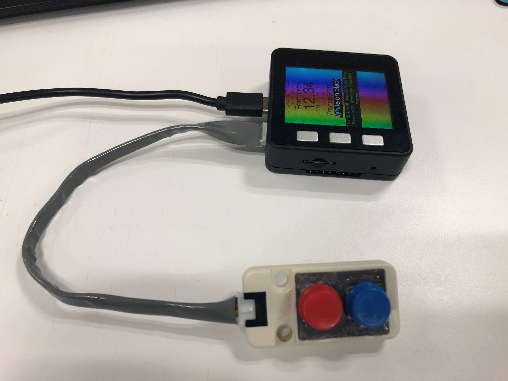
M5Stackの横にあるAポートに、こちらのM5Stack用デュアルボタンを差して、赤のボタンを押すと画面キャプチャーをSDカードに取得するようにします。また、画面キャプチャーの取得に数秒かかるので、その間画面を暗くします。
void setup()
{
...


  pinMode(21, INPUT_PULLUP); // red button
  pinMode(22, INPUT_PULLUP); // blue button

}

void loop()
{
...

  M5.update();
  int cur_value_red = digitalRead(21);
  int cur_value_blue = digitalRead(22);

  if (cur_value_red == 0)
  {
    Serial.println("RED button pushed");
    M5.Lcd.setBrightness(20);
    screenServer();
    M5.Lcd.setBrightness(200);
  }

}
サンプル
こちらにArduinoIDE用のサンプルを格納しました。TFT_Screen_Captureのようにカラーバーがランダムに表示されます。Bボタンを長押しすると、SDカードに画面キャプチャーを保存します。
ただし、下記にあるように、現時点ではM5Stackライブラリーが最新ではないため、手動でGitHubから最新のM5StackライブラリーをダウンロードしてWindowsであれば、ドキュメント\Arduino\libraries に配置する必要があります。
最後に
TFTの情報を読み取り、画面キャプチャーを取得するには、Add capability to read TFT SDA bi-directional pin対応されたTFT_eSPIと、こちらのサンプルを使用する必要がありました。Add capability to read TFT SDA bi-directional pinの更新は10日ほど前に本家のM5Stackのソースに取り込まれたようですが、まだ現時点の最新M5Stack 0.2.9ライブラリーには反映されていません。
メリークリスマス!
良いお年をお迎えください。