1. 背景
自宅前のゴミ捨て場がカラスに荒らされて嫌な思いをしたので、カラスを撃退するためのプロダクトを作ってGUGEN2019に応募しました。作品はコチラ:https://gugen.jp/entry2019/2019-080
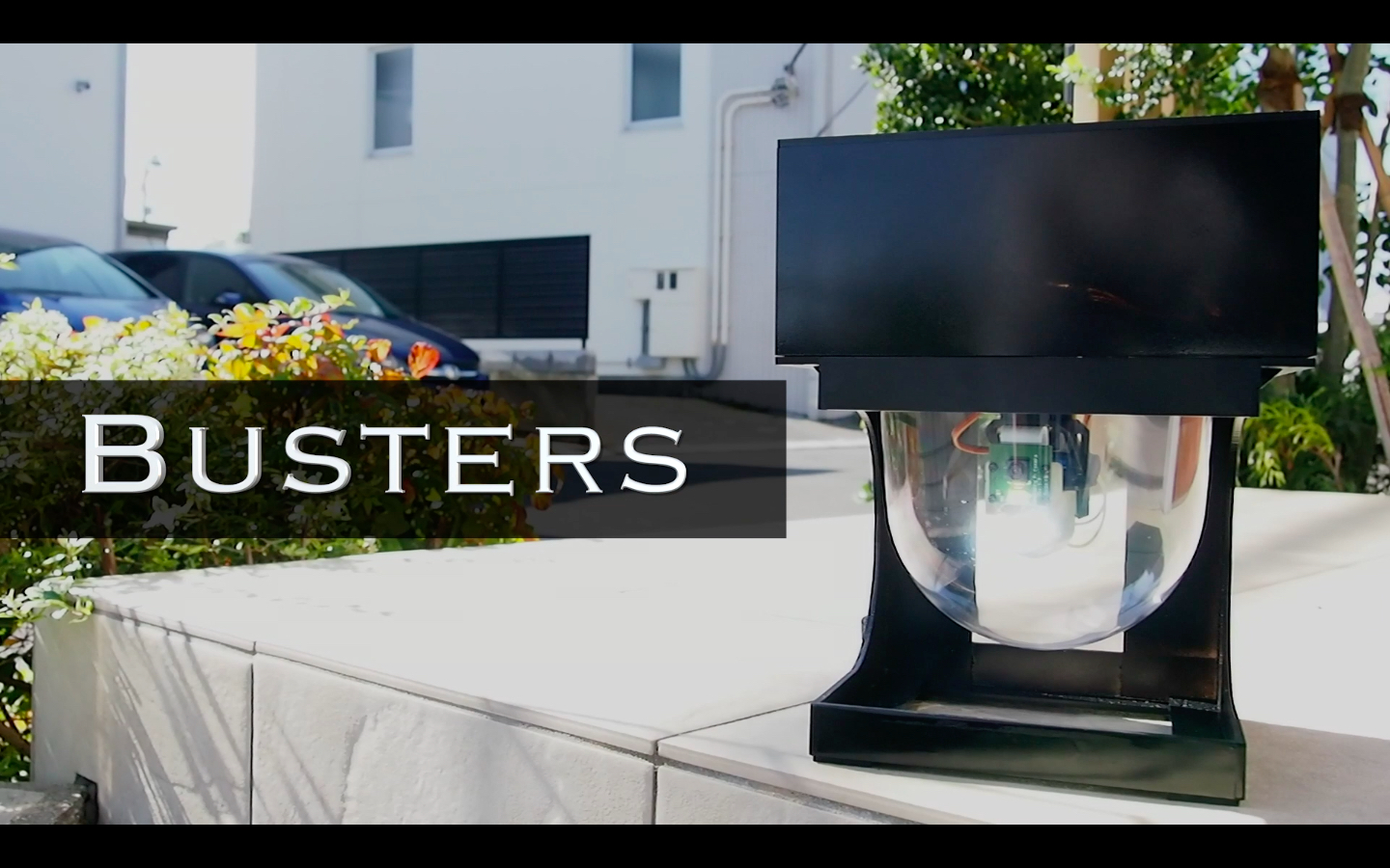
この機能の一部であるRaspberryPiとYOLOを使った自動追尾カメラは、いろんなことに応用できると思うので、投稿してみました。
2. 準備するもの
今回作りたいのは物体を認識して画像を自動で追尾する自動追尾カメラになります。したがって、下記の構成が必要となります。
・RaspberryPi:YOLOが実装されたもの
・カメラ:RaspberryPi用の純正カメラを使用
・サーボモータ(SG-90)×2:市販品を使用
・モータ台座:市販品を使用
・カメラの台座:3Dプリンタで自作
割と簡単に入手できるものばかりです。カメラの台座は3Dプリンタでの自作品ですが、固定できればなんでもOKです。完成後の全体像は下図のようになります。順を追って説明していきます。
2.1. RaspberryPi4へのYOLO v3-Tiny構築
現時点で高速に処理できそうな組み合わせとして、RaspberryPi4にYOLO3をインストールしました。使用したものはRaspberry Pi4 Model B 4GBで、RSコンポーネンツから購入しました。2019年末時点でここから購入が一番安かったです。
バージョン情報は下記の通り。
pi@raspberrypi:~ $ uname -a
Linux raspberrypi 4.19.75-v7l+ #1270 SMP Tue Sep 24 18:51:41 BST 2019 armv7l GNU/Linux

pi@raspberrypi:~ $ lsb_release -a
No LSB modules are available.
Distributor ID:	Raspbian
Description:	Raspbian GNU/Linux 10 (buster)
Release:	10
Codename:	buster
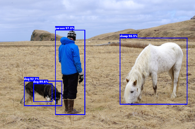
YOLO v3-Tinyの環境構築は、以下のサイトに沿って進めることで、環境構築&物体認識までできました!ここまでできれば環境構築としてはOKです。
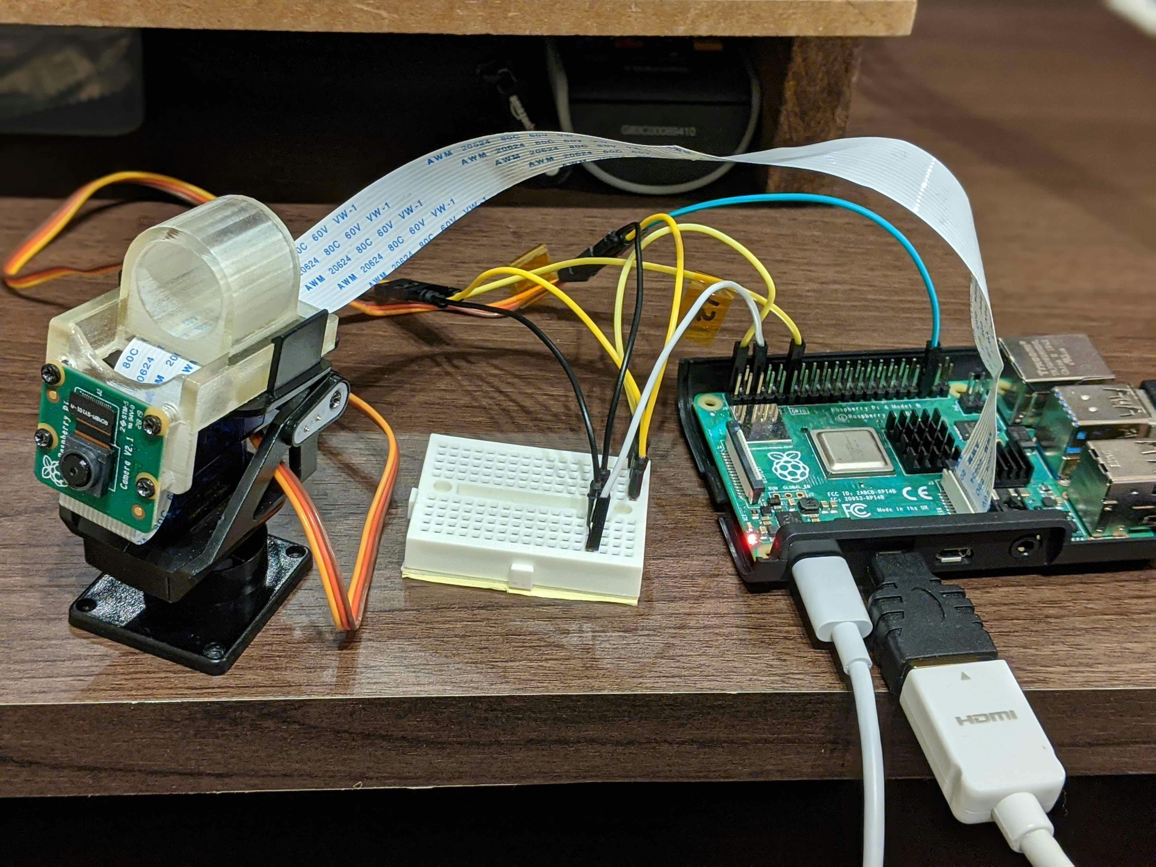
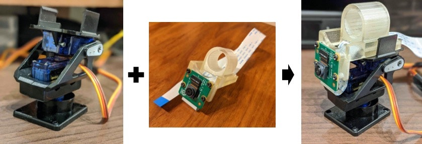
2.2. 部品の組み付け
サーボモータSG902個をモータ台座に、カメラ台座にカメラとフレキシブルケーブルを繋げます。そして、両者を組み付けます。これで駆動部の組み付けは完了です。
2.3. 配線
RaspberryPiと、カメラ&サーボモータを、ブレッドボード(小サイズ)とジャンパ線を使って下図のように接続します。

3. 実装
2.1で実装したYOLO v3-Tinyのコードを少し修正します。元のコードは上述の"Raspberry Pi で YOLO v3-Tiny / YOLO v3 による物体検出を試してみよう"に記載されているものを使わせていただきました。
https://github.com/neuralassembly/Tensorflow-YOLOv3
detect.pyを以下のように修正します。
import tensorflow as tf
import cv2
import sys
import picamera
import io
import numpy as np
import RPi.GPIO as GPIO
import wiringpi2 as wiringpi

from core.yolo_tiny import YOLOv3_tiny

def load_class_names():
    _CLASS_NAMES_FILE = './data/coco.names' #学習モデルのリスト
    """Returns a list of string corresonding to class names and it's length"""
    with open(_CLASS_NAMES_FILE, 'r') as f:
        class_names = f.read().splitlines()
    return class_names, len(class_names)

def getServoDutyHw(id, val):#サーボモータの設定
    val_min = 0
    val_max = 4095
    # デューティ比0%を0、100%を1024として数値を入力
    servo_min = 36   # 50Hz(周期20ms)、デューティ比3.5%: 3.5*1024/100=約36
    servo_max = 102  # 50Hz(周期20ms)、デューティ比10%: 10*1024/100=約102
    if id==1:
        servo_min = 53
        servo_max = 85
    duty = int((servo_min-servo_max)*(val-val_min)/(val_max-val_min) + servo_max)
    if duty > servo_max:
        duty = servo_max
    if duty < servo_min:
        duty = servo_min
    return duty

def main():
  #各種初期設定------------------
    #カメラの解像度
    CAMERA_WIDTH = 512
    CAMERA_HEIGHT = 384
    #GPIOの設定
    GPIO.setmode(GPIO.BCM)
    GPIO.setup(4, GPIO.OUT)
    GPIO.output(4, GPIO.LOW)
    #サーボモータで使用するピンNo.
    PWM0 = 19
    PWM1 = 18
    #サーボモータへの入力の初期値
    input_x = 2048
    input_y = 2048

    # wiringPiによるハードウェアPWM
    wiringpi.wiringPiSetupGpio() # GPIO名で番号を指定する
    wiringpi.pinMode(PWM0, wiringpi.GPIO.PWM_OUTPUT) # 左右方向のPWM出力を指定
    wiringpi.pinMode(PWM1, wiringpi.GPIO.PWM_OUTPUT) # 上下方向のPWM出力を指定
    wiringpi.pwmSetMode(wiringpi.GPIO.PWM_MODE_MS) # 周波数を固定するための設定
    wiringpi.pwmSetClock(375) # 50 Hz。18750/(周波数) の計算値に近い整数
    # PWMのピン番号とデフォルトのパルス幅をデューティ100%を1024として指定。
    # ここでは6.75%に対応する69を指定
    wiringpi.pwmWrite(PWM0, 69)
    wiringpi.pwmWrite(PWM1, 69)
  #----------------------------------

    class_names, n_classes = load_class_names()
    iou_threshold = 0.1
    confidence_threshold = 0.25
    model = YOLOv3_tiny(n_classes=n_classes,
                        iou_threshold=iou_threshold,
                        confidence_threshold=confidence_threshold)

    inputs = tf.placeholder(tf.float32, [1, *model.input_size, 3])
    detections = model(inputs)
    saver = tf.train.Saver(tf.global_variables(scope=model.scope))

    with tf.Session() as sess:
        saver.restore(sess, './weights/model-tiny.ckpt')

        stream = io.BytesIO()
        #cap = cv2.VideoCapture(0)
        cap = picamera.PiCamera()
        #カメラ解像度の設定 ※この値を変えたらutils_busters.pyの値も変更する
        cap.resolution = (CAMERA_WIDTH, CAMERA_HEIGHT)

        n = 0 #初期位置に戻すためのカウント

        while True:#ここからループ---------------------
            cap.capture(stream, format='jpeg') #カメラ撮影
            data = np.frombuffer(stream.getvalue(), dtype=np.uint8) #numpy型に変換
            frame = cv2.imdecode(data, 1) #opencv型に変換

            frame_size = (frame.shape[1], frame.shape[0])
            resized_frame = cv2.resize(frame, dsize=tuple((x) for x in model.input_size[::-1]), interpolation=cv2.INTER_NEAREST)
            result = sess.run(detections, feed_dict={inputs: [resized_frame]})

            cv2.imshow('frame', frame) #撮影画像の表示

            boxes_dict = result[0]
            resize_factor = (frame_size[0] / model.input_size[1], frame_size[1] / model.input_size[0])

            n = n + 1

            for cls in range(len(class_names)):
              boxes = boxes_dict[cls]

              if np.size(boxes) != 0 and class_names[cls] == "bird": #ターゲットが鳥の場合
                n=0 #初期位置戻しリセット
                for box in boxes:
                  xy = box[:4]
                  xy = [int(xy[i] * resize_factor[i % 2]) for i in range(4)]

                  target_x = int((xy[0]+xy[2])/2) #ターゲットの中心(水平方向)
                  target_y = int((xy[1]+xy[3])/2) #ターゲットの中心(垂直方向)
                  img_center_x = CAMERA_WIDTH/2 #水平方向のカメラ取込画素のの中心値
                  img_center_y = CAMERA_HEIGHT/2 #垂直方向のカメラ取込画素のの中心値
                  dx = img_center_x - target_x #ターゲットとカメラの中心ズレ(水平方向)
                  dy = img_center_y - target_y #ターゲットとカメラの中心ズレ(垂直方向)

                  input_x = input_x - 4 * dx #モータ入力値の更新。4は想定通り動くか確認して決めた実験値。
                  input_y = input_y - 4 * dy #モータ入力値の更新。4は想定通り動くか確認して決めた実験値。

                  if input_x > 4095: #モータが回りすぎないようににリミッタ設定
                      input_x = 4095
                  if input_x < 0: #モータが回りすぎないようににリミッタ設定
                      input_x = 0
                  if input_y > 2048: #モータが回りすぎないようににリミッタ設定
                      input_y = 2048
                  if input_y < 1500: #モータが回りすぎないようににリミッタ設定
                      input_y = 1500

                  duty0 = getServoDutyHw(0, input_x)
                  duty1 = getServoDutyHw(0, input_y)

                  print("ターゲット発見")
                  print("ターゲット中心:" + str(target_x) + ", " + str(target_y))
                  print("画像中心:" + str(img_center_x)+ ", " + str(img_center_y))
                  print("中心ズレ:" + str(dx) + ", " + str(dy))

                  if abs(dx) > 20: #dxが大きい時
                      if abs(dy) > 15: #dxもdyが大きい時は両方のモータ を動かす
                          wiringpi.pwmWrite(PWM0, duty0) #水平モータ駆動
                          wiringpi.pwmWrite(PWM1, duty1) #垂直モータ駆動

                      else: #dxが大きい時は水平方向のみのモータ を動かす
                          wiringpi.pwmWrite(PWM0, duty0) #水平モータ駆動

                  else: #dxが小さい時
                      if abs(dy) > 15: #dyが大きい時は垂直方向のモータ を動かす
                          wiringpi.pwmWrite(PWM1, duty1) #垂直モータ駆動

              else:
                  if n == 10: #10回検知しなかったら初期位置に戻す
                      wiringpi.pwmWrite(PWM0, 69)
                      wiringpi.pwmWrite(PWM1, 69)
                  elif n > 10:
                      n=11 #nを11でストップ

            stream.seek(0) #カメラのリセット

            if cv2.waitKey(1) & 0xFF == ord('q'): #「q」を押すと画面表示を停止
              break

        stream.seek(0) #カメラのリセット
        cap.close() #カメラキャプチャを停止
        cv2.destroyAllWindows() #画面ウインドを消去

if __name__ == '__main__':
    main()
今回は、鳥をターゲットにしているので106行目を以下のようにしています。
if np.size(boxes) != 0 and class_names[cls] == "bird": #ターゲットが鳥の場合
¥Tensorflow-YOLOv3¥data¥coco.namesに認識できる対象が記載されているので、ここに書かれているのものに書き換えれば他のものを検出することもできます。
4. 実行結果
上記スクリプトを実行します。ここで実行時のコマンドに注意。root権限と-eオプションが必要です。
$ sudo -E python3 detect_test.py
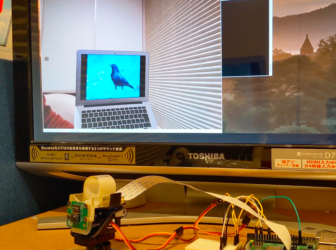
カラスの画像を表示したノートPCを動かして、それにカメラが追従してきているかを検証しました。実際に自動追尾している様子を撮影した動画はコチラです。
https://www.youtube.com/watch?v=48IRjJpwGYE
PCディスプレイ上に映っている画像は、自動追尾カメラのキャプチャ画像で、キャプチャ画像の中心にカラスがくるようにカメラが向きを変えて追尾していることがわかります!
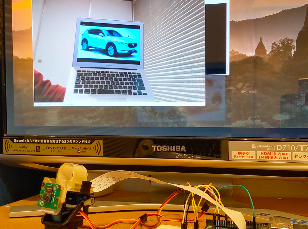
試しに、106行目のbirdをcarに変更して、車を追いかけるということもやってみました。その様子がコチラです。
https://www.youtube.com/watch?v=NnVF1ez1EwU
車も認識して追尾できていることを確認できました!
画像表示をやめて(96行目のcv.imshow行をコメントアウト)、処理速度を測ってみると、大体1fpsくらいの速度が出ていました。6,000円くらいのエッジデバイスでこのくらいの速度が出ればまあまあかな、と思います。
今回車で試したように、追尾できる対象も以下のようにたくさんあるので(自分で加えることもできそう:参考サイト)、いろんなことに使えそうです!
person
bicycle
car
motorbike
aeroplane
bus
train
truck
boat
traffic light
fire hydrant
stop sign
parking meter
bench
bird
cat
dog
horse
sheep
cow
elephant
bear
zebra
giraffe
backpack
umbrella
handbag
tie
suitcase
frisbee
skis
snowboard
sports ball
kite
baseball bat
baseball glove
skateboard
surfboard
tennis racket
bottle
wine glass
cup
fork
knife
spoon
bowl
banana
apple
sandwich
orange
broccoli
carrot
hot dog
pizza
donut
cake
chair
sofa
pottedplant
bed
diningtable
toilet
tvmonitor
laptop
mouse
remote
keyboard
cell phone
microwave
oven
toaster
sink
refrigerator
book
clock
vase
scissors
teddy bear
hair drier
toothbrush