目的
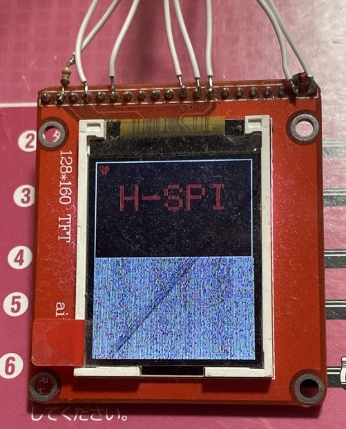
カラー化する
仮想VRAMの問題でなかなか進まなかったが
16ビットカラー化成功
//OLED_SSD1306_BITMAP_DV67_color_SPI_UNO
main.cpp
//OLED_SSD1306_BITMAP_DV67_color_SPI_UNO


//ヘッダーファイル
#include <Adafruit_GFX.h>
#include "hh.h"

//定義
#define SCREEN_WIDTH 128 // OLED display width, in pixels
//#define SCREEN_HEIGHT 160 // OLED display height, in pixels
#define SCREEN_HEIGHT 80 // OLED display height, in pixels stm32G071
NA_ST7735_P display(SCREEN_WIDTH, SCREEN_HEIGHT);


// ビットマップデータ
uint8_t databytes[8] =

{

0b01100110,
0b10101111,
0b10111111,
0b11011111,

0b01111110,
0b01111110,
0b00111100,
0b00011000

};


//初期化
void setup() {

  //ディスプレイの初期化
  display.begin();


  //表示方向
  display.setRotation(0);


  // 画面表示をクリア
  display.clearDisplay();

  //ビットマップの表示
  //display.drawBitmap(0, 0, databytes, 8, 8,  WHITE);
  display.drawBitmap(3, 3, databytes, 8, 8,  RED);


  // テキストサイズを設定
  display.setTextSize(3);
  // テキスト色を設定
  //display.setTextColor(WHITE);
  display.setTextColor(RED);
  // テキストの開始位置を設定
  display.setCursor(20, 20);


  // 1行目に46を表示
  display.println("H-SPI");

  // 画面の左側に長方形(塗りつぶしなし)を描画
  // display.drawRect(左上x, 左上y, 幅, 高さ, 線の色)
  display.drawRect(0, 0, 127, 80, WHITE);
  //display.drawRect(0, 0, 127, 159, WHITE);

  // 描画バッファの内容を画面に表示
  display.display();

  //delay(3000); //1秒待つ

}//setup


//メインループ
void loop() {
}//loop
hh.cpp
hh.cpp
//インクルド
#include "hh.h"
#include <Adafruit_GFX.h>
#include <SPI.h>


//定義


#define NA_ST7735_P_swap(a, b)                                                     \
  (((a) ^= (b)), ((b) ^= (a)), ((a) ^= (b))) ///< No-temp-var swap operation


//GPIOの設定1 開始
//GPIO
#define GPIO_D13(s) digitalWrite(13,s)
#define GPIO_D12(s) digitalWrite(12,s) //未使用
#define GPIO_D11(s) digitalWrite(11,s)
#define GPIO_D10(s) digitalWrite(10,s)
#define GPIO_D9(s)  digitalWrite(9,s)
#define GPIO_D8(s)  digitalWrite(8,s)
//#define GPIO_RESET(y)  GPIO_D9(y) //RESET=1


//1バイト送る
//#define GPIO_8BIT(s) SPI.transfer(s)


//1バイト送る
//#define GPIO_8BIT(s) SPI.transfer(s)


void NA_ST7735_P::GPIO_8BIT(uint8_t s)
{
  SPI.transfer(s);

/*
      digitalWrite(13,0);
  digitalWrite(11, (s >> 7) & 0x01);
      digitalWrite(13,0);
      digitalWrite(13,1);
      digitalWrite(13,0);
  digitalWrite(11, (s >> 6) & 0x01);
      digitalWrite(13,0);
      digitalWrite(13,1);
      digitalWrite(13,0);
  digitalWrite(11, (s >> 5) & 0x01);
      digitalWrite(13,0);
      digitalWrite(13,1);
      digitalWrite(13,0);
  digitalWrite(11, (s >> 4) & 0x01);
      digitalWrite(13,0);
      digitalWrite(13,1);
      digitalWrite(13,0);
  digitalWrite(11, (s >> 3) & 0x01);
      digitalWrite(13,0);
      digitalWrite(13,1);
      digitalWrite(13,0);
  digitalWrite(11, (s >> 2) & 0x01);
      digitalWrite(13,0);
      digitalWrite(13,1);
      digitalWrite(13,0);
  digitalWrite(11, (s >> 1) & 0x01);
      digitalWrite(13,0);
      digitalWrite(13,1);
      digitalWrite(13,0);
  digitalWrite(11, s & 0x01);
      digitalWrite(13,0);
      digitalWrite(13,1);
      digitalWrite(13,0);
*/

} //GPIO_8BIT

//コマンドの書き込み
void NA_ST7735_P::LCD_Write_CMD(uint8_t a)
{

  GPIO_D10(0);//CS=0; 12
  GPIO_D8(0); //A0=0; 9
      GPIO_8BIT(a);//P1=a; data SPI SPI
  GPIO_D10(1);//CS=1; 12

} //LCD_Write_CMD


//データ書き込み
void NA_ST7735_P::LCD_Write_Data(uint8_t a)
{

  GPIO_D10(0);//CS=0; 12
  GPIO_D8(1); //A0=1; 9
      GPIO_8BIT(a);//P1=a; data SPI SPI
  GPIO_D10(1);//CS=1; 12

} //LCD_Write_Data


//液晶の初期化処理
void NA_ST7735_P::TXDT144TF_ST7735S_Init(void)
{

  //----------  ST7735S Reset Sequence  --------//

//  GPIO_RESET(1);//LCD_RESET=1;
GPIO_D9(1);

  delay(1); //Delay 1ms

//  GPIO_RESET(0);//LCD_RESET=0;
GPIO_D9(0);

  delay(1); //Delay 1ms

//  GPIO_RESET(1);//LCD_RESET=1;
GPIO_D9(1);

  delay(120); //Delay 120ms

  LCD_Write_CMD(0x01);//SOFTWARE RESET
  delay(50);

  LCD_Write_CMD(0x01);//SOFTWARE RESET
  delay(50);

  LCD_Write_CMD(0x11);//SLEEP OUT
  delay(200);

  LCD_Write_CMD(0x29);//display on
  delay(100);

  LCD_Write_CMD(0x3a);//Interface pixel format
  LCD_Write_Data(0x05);//16bit mode
  delay(100);

  LCD_Write_CMD(0x36);//RGB-RGR format
  LCD_Write_Data(0x08);//RGB mode
  delay(100);


//while(1){} //debug


} //TXDT144TF_ST7735S_Init


NA_ST7735_P::NA_ST7735_P(uint8_t w, uint8_t h)
    : Adafruit_GFX(w, h), buffer(NULL)

{
}


//バッファのクリア
NA_ST7735_P::~NA_ST7735_P(void) {
  if (buffer) {
    free(buffer);
    buffer = NULL;
  }
}//~NA_ST7735_P


//初期処理
bool NA_ST7735_P::begin(void) {

  if ((!buffer) && !(buffer = (uint16_t *)malloc(WIDTH * HEIGHT * 2)   ))
    return false;

  //バッファーのクリア
  clearDisplay();

  //ポートのモード設定
  //アウトプットモード
  //pinMode(13, OUTPUT);
  //pinMode(12, OUTPUT); //未使用
  //pinMode(11, OUTPUT);
  pinMode(10, OUTPUT);
  pinMode(9, OUTPUT);
  pinMode(8, OUTPUT);


  //SPIの開始
  SPI.begin();


  //ビットの並び
  //SPI.setBitOrder(LSBFIRST);
  SPI.setBitOrder(MSBFIRST);   //桁大きい順


  //SPIの速度
  SPI.setClockDivider(SPI_CLOCK_DIV8);  // 2Mhz
  //SPI.setClockDivider(SPI_CLOCK_DIV4);
  //SPI.setClockDivider(SPI_CLOCK_DIV2);    //約8MHz


  //SPIクロックのモード
  SPI.setDataMode(SPI_MODE0);


  //ポートの初期化
  //GPIO_D13(1);//SPI_DATA=1
  //GPIO_D11(0);//SPI_CLK=1

  GPIO_D10(1);//CS=1
  GPIO_D9(1);//RESET=1
  GPIO_D8(0);//RS=0

  delay(500); //0.5秒待つ

  //液晶の初期化処理
  TXDT144TF_ST7735S_Init();

  //画面の書き込み開始
  //display();

  return true; // Success
}//begin


//点の表示
void NA_ST7735_P::drawPixel(int16_t x, int16_t y, uint16_t color) {
  if ((x >= 0) && (x < width()) && (y >= 0) && (y < height())) {
    // Pixel is in-bounds. Rotate coordinates if needed.
    switch (getRotation()) {
    case 1:
      NA_ST7735_P_swap(x, y);
      x = WIDTH - x - 1;
      break;
    case 2:
      x = WIDTH - x - 1;
      y = HEIGHT - y - 1;
      break;
    case 3:
      NA_ST7735_P_swap(x, y);
      y = HEIGHT - y - 1;
      break;
    }//end switch

    //ドットのカラーの設定
    buffer[ y_shift[y] | x ] = color;

  }//if
}//drawPixel

//バッファのクリア
void NA_ST7735_P::clearDisplay(void) {
  memset(buffer, 0, WIDTH * HEIGHT * 2 );
}


bool NA_ST7735_P::getPixel(int16_t x, int16_t y) {
  if ((x >= 0) && (x < width()) && (y >= 0) && (y < height())) {
    // Pixel is in-bounds. Rotate coordinates if needed.
    switch (getRotation()) {
    case 1:
      NA_ST7735_P_swap(x, y);
      x = WIDTH - x - 1;
      break;
    case 2:
      x = WIDTH - x - 1;
      y = HEIGHT - y - 1;
      break;
    case 3:
      NA_ST7735_P_swap(x, y);
      y = HEIGHT - y - 1;
      break;
    }
    return (buffer[ y_shift[y] | x ] );
  }
  return false; // Pixel out of bounds
}


uint16_t *NA_ST7735_P::getBuffer(void) { return buffer; }


//画面のリフレッシュ
void NA_ST7735_P::display(void) {

//buffer = (uint16_t*)yu; //とりま 仮想VRAMに実態を設定


//  uint16_t count = WIDTH * ((HEIGHT + 7) / 8);
//  uint16_t *ptr = buffer;

//    while (count--) {
//
//      //WIRE_WRITE(*ptr++);
//    }

//どつかから拾ってきたint を 文字列 にするアルゴリズム
//int a=0x01234567;
//char s[4];
//int *p;
//p=(int*)s;
//*p=a;


  //画面の書き込み開始
  LCD_Write_CMD(0x2C); //memory write


  char vg[2];
  uint16_t *ptr;  //ポインター型
  ptr = (uint16_t*)vg; //ポインターに実態の文字列を強制型変換して入れる

  for (int i = 0; i < (HEIGHT * WIDTH); i++) {

      *ptr=buffer[i]; //ptr と vg は、ポインタでリンクしている
//---------------- 1バイト目


          LCD_Write_Data(vg[1]);


//---------------- 2バイト目


          LCD_Write_Data(vg[0]);


  }//i


}//display
hh.h
hh.h
#ifndef _NA_ST7735_P_H_
#define _NA_ST7735_P_H_

#include <Adafruit_GFX.h>

#ifndef NO_ADAFRUIT_NA_ST7735_P_COLOR_COMPATIBILITY
#define BLACK NA_ST7735_P_BLACK     ///< Draw 'off' pixels
#define WHITE NA_ST7735_P_WHITE     ///< Draw 'on' pixels
#define RED NA_ST7735_P_RED     ///< Draw 'on' pixels
//#define INVERSE NA_ST7735_P_INVERSE ///< Invert pixels
#endif
/// fit into the SSD1306_ naming scheme
#define NA_ST7735_P_BLACK 0x0000   ///< Draw 'off' pixels
#define NA_ST7735_P_WHITE 0xffff   ///< Draw 'on' pixels
#define NA_ST7735_P_RED 0b1111100000000000 //red

///< Draw 'on' pixels
//#define NA_ST7735_P_INVERSE 2 ///< Invert pixels


class NA_ST7735_P : public Adafruit_GFX {
public:

  NA_ST7735_P(uint8_t w, uint8_t h);

  ~NA_ST7735_P(void);

  bool begin(void);
  void display(void);
  void clearDisplay(void);
  void drawPixel(int16_t x, int16_t y, uint16_t color);
  bool getPixel(int16_t x, int16_t y);
  uint16_t *getBuffer(void);

  void GPIO_8BIT(uint8_t s);
  void LCD_Write_CMD(uint8_t ww);
  void LCD_Write_Data(uint8_t ii);
  void TXDT144TF_ST7735S_Init(void);


protected:


  uint16_t *buffer; ///< Buffer data used for display buffer. Allocated when
                   ///< begin method is called.


uint16_t y_shift[160]={
0,128,256,384,512,640,768,896,1024,1152,
1280,1408,1536,1664,1792,1920,2048,2176,2304,2432,
2560,2688,2816,2944,3072,3200,3328,3456,3584,3712,
3840,3968,4096,4224,4352,4480,4608,4736,4864,4992,
5120,5248,5376,5504,5632,5760,5888,6016,6144,6272,
6400,6528,6656,6784,6912,7040,7168,7296,7424,7552,
7680,7808,7936,8064,8192,8320,8448,8576,8704,8832,
8960,9088,9216,9344,9472,9600,9728,9856,9984,10112,
10240,10368,10496,10624,10752,10880,11008,11136,11264,11392,
11520,11648,11776,11904,12032,12160,12288,12416,12544,12672,
12800,12928,13056,13184,13312,13440,13568,13696,13824,13952,
14080,14208,14336,14464,14592,14720,14848,14976,15104,15232,
15360,15488,15616,15744,15872,16000,16128,16256,16384,16512,
16640,16768,16896,17024,17152,17280,17408,17536,17664,17792,
17920,18048,18176,18304,18432,18560,18688,18816,18944,19072,
19200,19328,19456,19584,19712,19840,19968,20096,20224,20352
};


};

#endif // _NA_ST7735_P_H_