今回の目標は、Faster R-CNNによる物体検出を併用してMoveNetで複数人の姿勢推定を行うことである。
これを検証しようと考えたきっかけは、自身でMoveNetを再現実装していた時、SinglePoseモデル(1人の人間のみに姿勢推定をかけるモデル)は難なく再現できたが、MultiPoseモデル(複数人の姿勢推定を同時に行えるモデル)に苦戦していたことである。
そこで思いついたのが、「1枚の画像に写る人間1人1人を物体検出し、検出された人間1人1人にSinglePoseで姿勢推定をかけられないか」というアイデアであり、MultiPoseを使わず複数人の姿勢推定を行えるのであれば結果オーライということで検証するに至った。
目次
目指す機能
物体検出のアノテーションと切り出し
姿勢推定のキーポイント描画
オリジナル画像への反映
思わぬ収穫
参考にした記事等
- <開発環境>
- Python 3.12.4
- VScode
目指す機能
以下のような画像に対してFaster R-CNNとMoveNetのSinglePoseを使い、複数人の姿勢推定を行う。

姿勢推定のキーポイントは以下の左画像のようなもの(右は描画前のオリジナル)で、若干のズレはあるが概ね推定できており、今回の検証は精度より実現可否を重視したものであるため、これが複数人の上に描画されれば成功とする。


物体検出のアノテーションと切り出し
まずFaster R-CNNによる物体検出を実装していく。
Faster R-CNNを採用した理由は、リアルタイムの処理には不向きだが精度が高いとされているためである。
なお、自身のPytorchの経験獲得も兼ねているため、使い慣れたTensorFlowとPytorchが混在している。
import os
import csv
import torch
from torchvision.models.detection import fasterrcnn_resnet50_fpn, FasterRCNN_ResNet50_FPN_Weights
from torchvision.transforms import functional as F
from PIL import Image
import matplotlib.pyplot as plt
import pandas as pd
import numpy as np
from PIL import Image
import shutil
import cv2
from PIL import Image
import tensorflow as tf
import tensorflow_hub as hub

# Faster R-CNNモデルのロード(weightsを指定)
weights = FasterRCNN_ResNet50_FPN_Weights.COCO_V1
model = fasterrcnn_resnet50_fpn(weights=weights)
model.eval()

# 画像ファイルパス
image_path = 'hoge/hoge.png'

# 出力先フォルダ
output_folder = 'hoge/cropped'
detection_output_folder = 'hoge/data'
os.makedirs(output_folder, exist_ok=True)

# CSV保存先
    csv_file_path = 'hoge/data/hoge.csv'

def detect_person(image_path, output_filename):
    # 画像読み込み
    image = Image.open(image_path).convert("RGB")
    image_tensor = F.to_tensor(image)

    # 物体検出
    with torch.no_grad():
        predictions = model([image_tensor])[0]

    # 検出結果の描画
    plt.figure(figsize=(10, 10))
    plt.imshow(image)
    ax = plt.gca()

    # CSVデータを格納するリスト
    csv_data = []

    for i, box in enumerate(predictions['boxes']):
        score = predictions['scores'][i].item()
        label = predictions['labels'][i].item()
        if label == 1 and score > 0.8:  # '1' はCOCOデータセットで「人間」を指す
            # 座標を整数に変換
            x1, y1, x2, y2 = map(int, box.tolist())

            # バウンディングボックス領域を切り出し
            cropped_image = image.crop((x1, y1, x2, y2))

            # 切り出し画像の保存パスと名前を生成
            cropped_image_filename = f"{os.path.splitext(output_filename)[0]}_cropped_{i+1}.png"
            cropped_image_path = os.path.join(output_folder, cropped_image_filename)
            cropped_image.save(cropped_image_path)

            # CSV用データを追加
            csv_data.append({
                "original": os.path.basename(image_path),
                "file": cropped_image_filename,
                "annotation": f"{x1},{y1},{x2},{y2}"
            })

            # バウンディングボックスを描画
            ax.add_patch(plt.Rectangle((x1, y1), x2 - x1, y2 - y1, fill=False, color='red', linewidth=3))
            ax.text(x1, y1, f'Person: {score:.2f}', color='white', backgroundcolor='red')


    plt.axis("off")

    # 保存先のパスを設定
    detection_image_path = os.path.join(detection_output_folder, output_filename)
    plt.savefig(detection_image_path, bbox_inches='tight', pad_inches=0)
    plt.close()

    # CSVファイルへの書き込み
    write_to_csv(csv_file_path, csv_data)

def write_to_csv(csv_path, data):
    # CSVファイルに書き込み
    write_header = not os.path.exists(csv_path)

    with open(csv_path, mode='a', newline='', encoding='utf-8') as csvfile:
        writer = csv.DictWriter(csvfile, fieldnames=["original", "file", "annotation"])
        if write_header:
            writer.writeheader()
        writer.writerows(data)

# 物体検出を実行
original_filename = os.path.basename(image_path)
output_filename = f"{os.path.splitext(original_filename)[0]}_detected.png"
detect_person(image_path, output_filename)
上記コードによる物体検出結果と切り出した画像の一部が以下の3枚である。
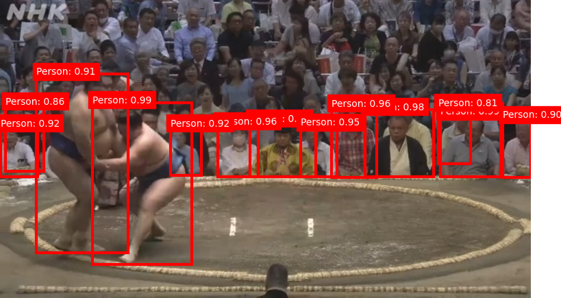
物体検出結果


物体検出については、画像に写るすべての人物を検出できてはいないが、ひとまず10人以上検出できているので今回は充分とする。
そしてバウンディングボックスが描画された箇所をそれぞれ1枚の画像として切り出し別フォルダに格納できているので、姿勢推定をかけていく。
バウンディングボックスの座標等をcsvファイルで出力した意図や理由については後述する。
姿勢推定のキーポイント描画
切り出された画像に姿勢推定を行い、キーポイントとそれらを結ぶ線分を描画する。
最終的にオリジナル画像の上に何枚も重ねてオーバーレイ画像とするため、背景を透過させておく。
また、サイズが小さい画像は姿勢推定時に自動でサイズ調整されることがあるので、自分で一度画像を拡大させてからリサイズ。
# キーポイントと線分の色
KEYPOINT_DICT = {
    'nose': 0,
    'left_eye': 1,
    'right_eye': 2,
    'left_ear': 3,
    'right_ear': 4,
    'left_shoulder': 5,
    'right_shoulder': 6,
    'left_elbow': 7,
    'right_elbow': 8,
    'left_wrist': 9,
    'right_wrist': 10,
    'left_hip': 11,
    'right_hip': 12,
    'left_knee': 13,
    'right_knee': 14,
    'left_ankle': 15,
    'right_ankle': 16
}

KEYPOINT_EDGE_INDS_TO_COLOR = {
    (0, 1): 'm',
    (0, 2): 'c',
    (1, 3): 'm',
    (2, 4): 'c',
    (0, 5): 'm',
    (0, 6): 'c',
    (5, 7): 'm',
    (7, 9): 'm',
    (6, 8): 'c',
    (8, 10): 'c',
    (5, 6): 'y',
    (5, 11): 'm',
    (6, 12): 'c',
    (11, 12): 'y',
    (11, 13): 'm',
    (13, 15): 'm',
    (12, 14): 'c',
    (14, 16): 'c'
}

def keypoints_edges(keypoints_with_scores, height, width, keypoint_threshold=0.11):
    keypoints_all = []
    keypoint_edges_all = []
    edge_colors = []
    keypoints = keypoints_with_scores['output_0']
    num_instances, _, _, _ = keypoints.shape

    for idx in range(num_instances):
        kpts_x = keypoints[0, idx, :, 1]
        kpts_y = keypoints[0, idx, :, 0]
        kpts_scores = keypoints[0, idx, :, 2]
        kpts_absolute_xy = np.stack([width * np.array(kpts_x), height * np.array(kpts_y)], axis=-1)
        kpts_above_thresh_absolute = kpts_absolute_xy[kpts_scores > keypoint_threshold, :]
        keypoints_all.append(kpts_above_thresh_absolute)

        for edge_pair, color in KEYPOINT_EDGE_INDS_TO_COLOR.items():
            if (kpts_scores[edge_pair[0]] > keypoint_threshold and kpts_scores[edge_pair[1]] > keypoint_threshold):
                x_start = kpts_absolute_xy[edge_pair[0], 0]
                y_start = kpts_absolute_xy[edge_pair[0], 1]
                x_end = kpts_absolute_xy[edge_pair[1], 0]
                y_end = kpts_absolute_xy[edge_pair[1], 1]
                line_seg = np.array([[x_start, y_start], [x_end, y_end]])
                keypoint_edges_all.append(line_seg)
                edge_colors.append(color)
    if keypoints_all:
        keypoints_xy = np.concatenate(keypoints_all, axis=0)
    else:
        keypoints_xy = np.zeros((0, 2))

    if keypoint_edges_all:
        edges_xy = np.stack(keypoint_edges_all, axis=0)
    else:
        edges_xy = np.zeros((0, 2, 2))
    return keypoints_xy, edges_xy, edge_colors

def draw_keypoints_and_edges_only(image, keypoints_with_scores, output_image_height=None):
    height, width, _ = image.shape
    transparent_bg = np.zeros((height, width, 4), dtype=np.uint8)

    (keypoint_locs, keypoint_edges, edge_colors) = keypoints_edges(keypoints_with_scores, height, width)

    # キーポイントを描画(基本はradius=3なので、大きさは自由に調整)
    for loc in keypoint_locs:
        cv2.circle(transparent_bg, (int(loc[0]), int(loc[1])), radius=30, color=(0, 0, 255, 255), thickness=-1)

    # 線分を描画(基本はthickness=2なので、太さは自由に調整)
    for edge, color in zip(keypoint_edges, edge_colors):
        start = (int(edge[0, 0]), int(edge[0, 1]))
        end = (int(edge[1, 0]), int(edge[1, 1]))
        line_color = {
            'm': (255, 0, 255, 255),
            'c': (0, 255, 255, 255),
            'y': (255, 255, 0, 255)
        }[color]
        cv2.line(transparent_bg, start, end, line_color, thickness=25)

    if output_image_height is not None:
        scale = output_image_height / height
        new_size = (int(width * scale), output_image_height)
        transparent_bg = cv2.resize(transparent_bg, dsize=new_size, interpolation=cv2.INTER_CUBIC)
    return transparent_bg

# MoveNetをロード
movenet = hub.load("https://tfhub.dev/google/movenet/singlepose/lightning/4").signatures['serving_default']

# 画像ディレクトリ
input_folder = 'hoge/cropped'
output_folder = 'hoge/overlay'

# 入力ディレクトリ内のすべての画像ファイルに対して処理
for image_filename in os.listdir(input_folder):
    if image_filename.endswith(('.png', '.jpg', '.jpeg')):
        image_path = os.path.join(input_folder, image_filename)

        # 画像の読み込み
        image = Image.open(image_path).convert("RGB")
        original_size = image.size

        # 画像を6倍に拡大
        large_image = image.resize((original_size[0] * 6, original_size[1] * 6), Image.Resampling.LANCZOS)
        large_image_np = np.array(large_image)

        # MoveNetモデルの入力形式でリサイズ
        input_image = tf.convert_to_tensor(large_image_np)
        input_image = tf.expand_dims(input_image, axis=0)
        input_image = tf.image.resize_with_pad(input_image, 192, 192)

        # 画像を int32 型にキャスト
        input_image = tf.cast(input_image, tf.int32)

        # 姿勢推定を実行
        keypoints_with_scores = movenet(input_image)

        # 背景透明のキーポイントと線分描画画像を生成
        output_overlay = draw_keypoints_and_edges_only(large_image_np, keypoints_with_scores)

        # 元のサイズに縮小
        output_overlay = cv2.resize(output_overlay, original_size, interpolation=cv2.INTER_AREA)

        # 画像を保存
        output_image_path = os.path.join(output_folder, image_filename)
        cv2.imwrite(output_image_path, output_overlay)
オリジナル画像への反映
キーポイントの画像を、csvファイルに記録したバウンディングボックスの座標を元にオリジナル画像(のコピー)に上書き描画していく。
前の工程でcsvファイルを出力し座標を管理していた件についてだが、当初は辞書型データとして単純に座標を受け渡していた。
しかしその方法だと姿勢推定結果のキーポイント画像と対応させる処理がなかなかうまくいかず、データベースを使い慣れた人間としては対応表のような形で出力して確定させておく方が感覚的に扱いやすかったため、csvファイルを作成することにした。
# ファイルパス
overlay_folder = 'hoge/data/overlay'
data_folder = 'hogedata'
csv_file = 'hoge/data/hoge.csv'

# detections.csvの読み込み
df = pd.read_csv(csv_file)

# originalカラムに記載した画像をdataフォルダにコピー
copied_images = set()

def copy_original_image(original_image_name):
    if original_image_name not in copied_images:
        original_image_path = os.path.join(data_folder, original_image_name)
        final_image_path = os.path.join(data_folder, f"final_{original_image_name}")
        if os.path.exists(original_image_path):
            shutil.copy(original_image_path, final_image_path)
            copied_images.add(original_image_name)
            print(f"Copied original image: {original_image_name}")
        else:
            print(f"Original image not found: {original_image_name}")
    else:
        print(f"Image {original_image_name} already copied.")

# 画像の重ね合わせ
def overlay_images(original_image_path, overlay_image_path, annotation):
    original_image = Image.open(original_image_path).convert("RGBA")
    overlay_image = Image.open(overlay_image_path).convert("RGBA")

    # 座標取得(x_min, y_min, x_max, y_max)
    x_min, y_min, x_max, y_max = map(int, annotation.split(','))

    # 元画像にオーバーレイ画像を重ねる(指定座標に配置)
    original_image.paste(overlay_image, (x_min, y_min, x_max, y_max), overlay_image)

    return original_image

# 最終画像を作成
for index, row in df.iterrows():
    original_image_name = row['original']
    annotation = row['annotation']
    file_name = row['file']

    # originalカラムで指定した画像をコピーする処理
    copy_original_image(original_image_name)

    # dataフォルダ内でfinal_がついたoriginal画像を検索
    final_image_path = os.path.join(data_folder, f"final_{original_image_name}")

    # overlayフォルダ内で対応するオーバーレイ画像を検索
    overlay_image_path = os.path.join(overlay_folder, file_name)

    if os.path.exists(final_image_path) and os.path.exists(overlay_image_path):
        # オーバーレイ処理を行う
        print(f"Processing: {original_image_name} with overlay {file_name}")
        overlaid_image = overlay_images(final_image_path, overlay_image_path, annotation)

        # 最終的な画像をfinal_で保存
        overlaid_image.save(final_image_path)
        print(f"Updated final image saved as: {final_image_path}")
    else:
        # 画像が存在しない場合
        if not os.path.exists(final_image_path):
            print(f"Final image not found: {final_image_path}")
        if not os.path.exists(overlay_image_path):
            print(f"Overlay image not found: {overlay_image_path}")
上記の実行結果が以下の画像。

物体検出時の画像と見比べても、キーポイント画像を重ねる座標は完全に一致している。

アバウトではあるが、物体検出で特定した人物であればMoveNetのMultiPoseを使わずとも姿勢推定できており、目的は達成できた。
精度以外の改善点としては、キーポイント画像をすべて上書きしてから保存すると最後に上書きしたキーポイント画像以外リセットされてしまうため、キーポイント画像を1枚重ねるごとにオーバーレイ画像の保存処理をせねばならず、画像の生成に時間がかかってしまう点が目立った。
思わぬ収穫
今回の最大の収穫は、バウンディングボックスの座標のような中間データをファイル出力して管理する利点に気づけたことであった。
今回はバウンディングボックスの座標しかcsvファイルに記録しなかったが、姿勢推定のキーポイントの座標なども記載し、後でcsvファイル内のデータをクレンジングすれば、そのままアノテーションデータをまとめた学習用データセットとしてファインチューニングで流用できる。
仮に自分で一からデータセットを作成しようとすると膨大な時間がかかってしまうが、モデルの推定結果や中間データを適切な形で外部化しておくことでそのコストを減らせるのは大きな恩恵かもしれない。
また、出力した中間データを参照することで、開発者側で評価関数以外の観点からも推定結果の妥当性判断できたり、中間データの内容を受けてモデルのパラメータをどのように調整するかなどチェックしやすくなったりすると思われる。
人工知能開発におけるある種の「デバッグ」の知見を得られたことは、まさに目から鱗が落ちるような経験であった。