はじめに
いろいろとロボットに触れて作ってみたりしていたが,メカナムホイールを動かしたことはなかった.もちろん,見たことはあり,前から動かしてみたいなと思っていた.2023年のクリスマスにメカナムホイールロボットを手に入れたので,それを組み立てて動かすことで,メカナムホイールロボットについて整理する.その中でつまづいた点についても記述する.
組み立てるメカナムホイールロボット
今回,手に入れた組み立てキットについて記載する.
Amazonでの購入ページ情報
OSOYOO メカナムホイール ロボットカーシャーシ 4WD 80mm DC12Vモーター スマートロボット ミニ四駆 台車ロボットSTEM 組み立ておもちゃアルドゥイーノ Raspberry Pi micro bit適用 360°全方向移動Omni directional DIY 税込み 8,999円(2024/2/24現在)
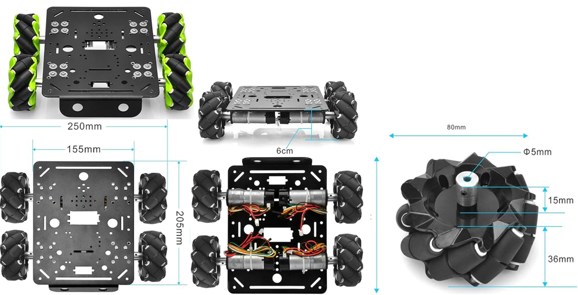
(実は,中央下の図における車輪の取り付けは間違っているため注意)
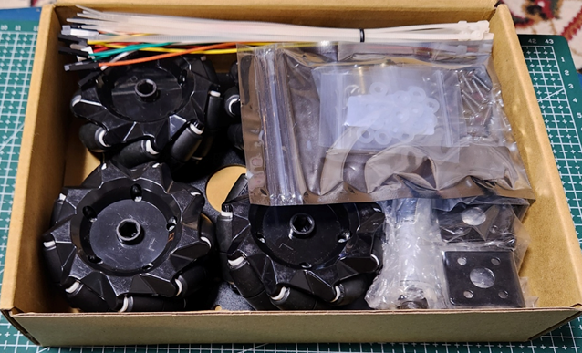
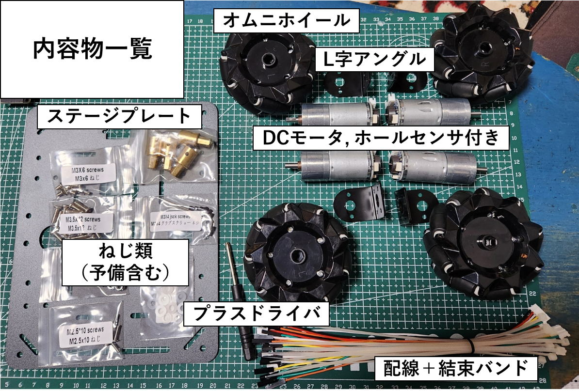
実物
比較的にきれいに梱包されていた.気に入った点は,コネクタ付き線や結束バンドが含まれていた点である.さらに,ホールセンサもモータに取り付けられている.1万円手前の値段だけある.
組み立て
ロボットの組み立て自体はシンプルであるため詳細は割愛する.
ただ,組み立て手順書などは含まれていないため,注意しながら組み立てる必要がある.
組み立て失敗談
組み立てはシンプルと言いながら,一つ間違えた.それはホイールの取り付けである.
メカナムホイールは組み立てた後の制御で勉強したため,取り付けるべき方向を知らなかった.
しかも,製品のホイールにはR, Lの表記はあったが,それに従って間違った.その表記が間違っていることになる.正しくは,45度の小さな回転体の軸がロボットの中心を向くように取り付ける.
色々と足して組み立て
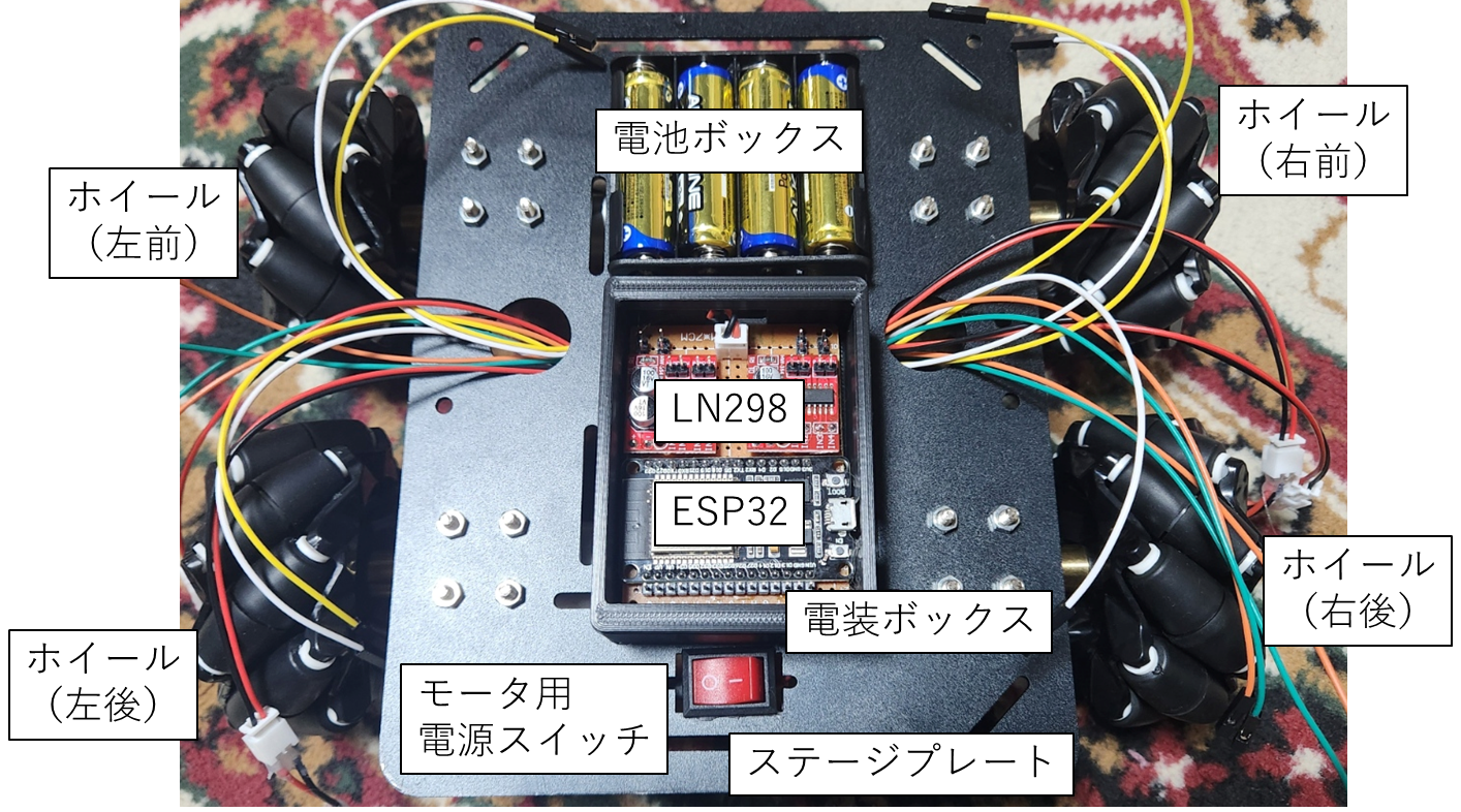
電池ボックス,モータドライバ,マイコン,スイッチなどは付属されていないため,色々と準備した.
今回は,4輪駆動であるため,モータ4つを制御する必要がある.そのため,デュアルモータドライバモジュールLN298を2つ用いることとした.マイコンボードはESP32として,電離ボックスは単三4本にした.スイッチがついていなかったため,スイッチを別で用意.さらに電装類をまとめたかったため,後述するが,ユニバーサル基板にまとめ,それを格納するための電装ボックスを設計して3Dプリンタで印刷.
(下図は,実験時点での図)
配線
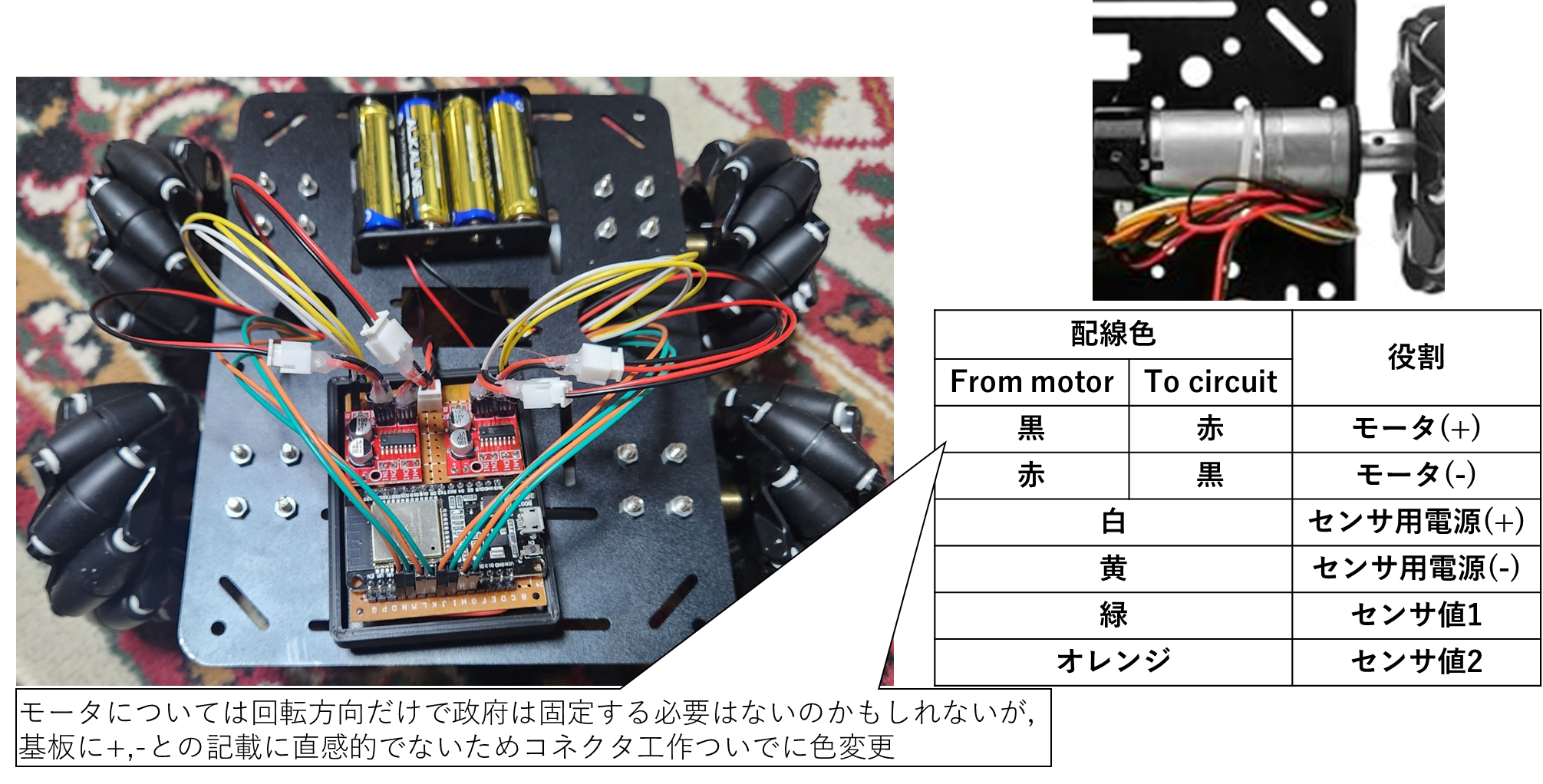
モータからの配線種類
まず,モータから出ている配線について整理する.
各モータには小さな基盤がついており,6種類の端子がある.
下図にあるように,モータへの電源供給線2本,センサ用電源2本,センサ信号線2本である.
モータのコネクタがXH-2P-Fであり,使いづらかった.コネクタ掛け変えてもよかったが,
基板に記載されているモータの端子名M+, M-に対して,線色が直感的でなく,
ちょうど手元にXHコネクタがあったこともあり,変換ケーブルを作成.
電装系統への配線
少しわかりづらいかもしれないが,4つのモータすべての配線について図に示した.
電装ボックスの内部構成については後で詳細に記述する.
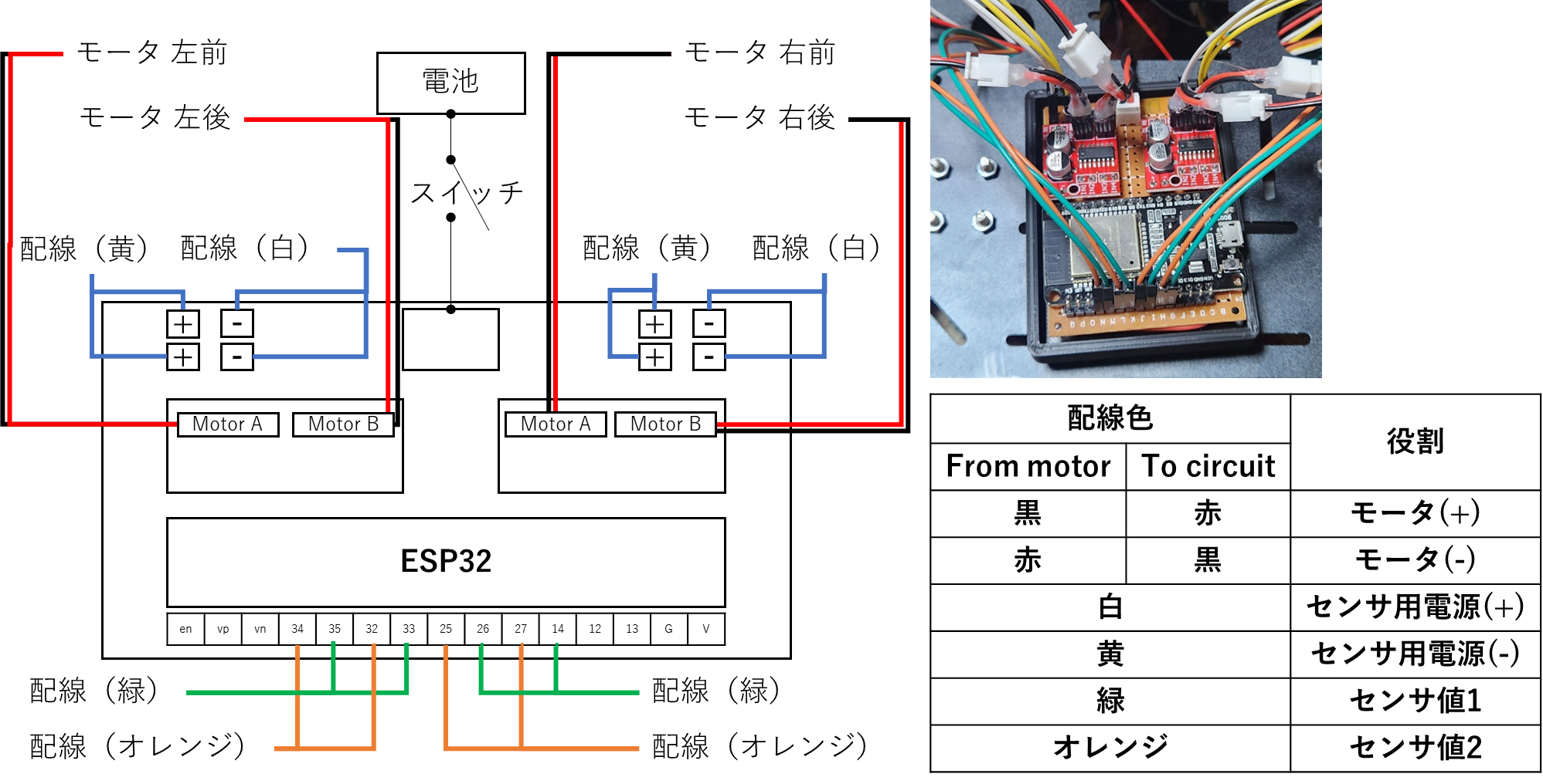
電装ボックスの内部構成
図において1, 2, 3, 4というのは,それぞれIN1, IN2, IN3, IN4を示しており,
制御量を受け付ける入力ピンである.PWM信号が扱えるピンとつないでいる.

メカナムホイールの制御
幾何学的な動作確認
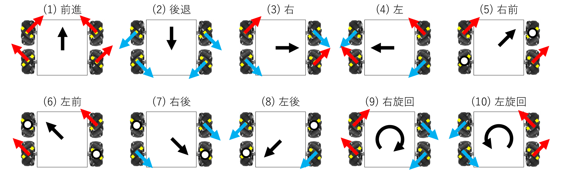
まず,メカナムホイールの特徴としては,45度に取り付けられた回転体である.この回転体の軸が中心に向くようにすると,以下の図のようになる.枠内の赤矢印,青矢印はモータの回転方向であり,白丸は静止を意味する.タイヤの黄色破線は回転体の軸を示す.タイヤの赤矢印はモータの回転方向に合わせた移動方向である.色で対応付けしており,赤色方向へのモータ回転であれば,赤矢印がタイヤの移動方向であり,青色方向へのモータ回転であれば,青矢印がタイヤの移動方向である.

それぞれのベクトルの足し合わせにより,下図に示す10種類のメカナムホイールロボットにおける基本移動を実現することができる.比較的わかりやすい構成である.このように整理するとプログラムも組みやすい.
プログラム
プログラムの構成は以下のようにした
- OTA.h
- OTAに関するヘッダファイル
- mecanum_pwm_motor.h
- PWM設定からメカナムホイールを簡単に動かすための関数を定義
- main.cpp
OTA.h
#ifdef ESP32
#include <WiFi.h>
#include <ESPmDNS.h>
#else
#include <ESP8266WiFi.h>
#include <ESP8266mDNS.h>
#endif

#include <WiFiUdp.h>
#include <ArduinoOTA.h>

#if defined(ESP32_RTOS) && defined(ESP32)
void ota_handle( void * parameter ) {
  for (;;) {
    ArduinoOTA.handle();
    delay(3500);
  }
}
#endif

void setupOTA(const char* nameprefix, const char* ssid, const char* password) {
  // Configure the hostname
  uint16_t maxlen = strlen(nameprefix) + 7;
  char *fullhostname = new char[maxlen];
  uint8_t mac[6];
  WiFi.macAddress(mac);
  snprintf(fullhostname, maxlen, "%s-%02x%02x%02x", nameprefix, mac[3], mac[4], mac[5]);
  ArduinoOTA.setHostname(fullhostname);
  delete[] fullhostname;

  // Configure and start the WiFi station
  WiFi.mode(WIFI_STA);
  WiFi.begin(ssid, password);

  // Wait for connection
  while (WiFi.waitForConnectResult() != WL_CONNECTED) {
    Serial.println("Connection Failed! Rebooting...");
    delay(5000);
    ESP.restart();
  }

  ArduinoOTA.onStart([]() {
	//NOTE: make .detach() here for all functions called by Ticker.h library - not to interrupt transfer process in any way.
    String type;
    if (ArduinoOTA.getCommand() == U_FLASH)
      type = "sketch";
    else // U_SPIFFS
      type = "filesystem";

    // NOTE: if updating SPIFFS this would be the place to unmount SPIFFS using SPIFFS.end()
    Serial.println("Start updating " + type);
  });

  ArduinoOTA.onEnd([]() {
    Serial.println("\nEnd");
  });

  ArduinoOTA.onProgress([](unsigned int progress, unsigned int total) {
    Serial.printf("Progress: %u%%\r", (progress / (total / 100)));
  });

  ArduinoOTA.onError([](ota_error_t error) {
    Serial.printf("Error[%u]: ", error);
    if (error == OTA_AUTH_ERROR) Serial.println("\nAuth Failed");
    else if (error == OTA_BEGIN_ERROR) Serial.println("\nBegin Failed");
    else if (error == OTA_CONNECT_ERROR) Serial.println("\nConnect Failed");
    else if (error == OTA_RECEIVE_ERROR) Serial.println("\nReceive Failed");
    else if (error == OTA_END_ERROR) Serial.println("\nEnd Failed");
  });

  ArduinoOTA.begin();

  Serial.println("OTA Initialized");
  Serial.print("IP address: ");
  Serial.println(WiFi.localIP());

#if defined(ESP32_RTOS) && defined(ESP32)
  xTaskCreate(
    ota_handle,          /* Task function. */
    "OTA_HANDLE",        /* String with name of task. */
    10000,            /* Stack size in bytes. */
    NULL,             /* Parameter passed as input of the task */
    1,                /* Priority of the task. */
    NULL);            /* Task handle. */
#endif
}
mecanum_pwm_motor.h
// 参考:https://rikoubou.hatenablog.com/entry/2017/06/05/172953

#include <Arduino.h>

/* 使うピンの定義 */
// Left
const int LEFT_IN1 = 23;
const int LEFT_IN2 = 22;
const int LEFT_IN3 = 1;
const int LEFT_IN4 = 3;
// Right
const int RIGHT_IN1 = 4;
const int RIGHT_IN2 = 16;
const int RIGHT_IN3 = 15;
const int RIGHT_IN4 = 2;

/* チャンネルの定義 */
const int CHANNEL_0 = 0;
const int CHANNEL_1 = 1;
const int CHANNEL_2 = 2;
const int CHANNEL_3 = 3;
const int CHANNEL_4 = 4;
const int CHANNEL_5 = 5;
const int CHANNEL_6 = 6;
const int CHANNEL_7 = 7;

const int LEDC_TIMER_BIT = 8;   // PWMの範囲(8bitなら0〜255、10bitなら0〜1023)
const int LEDC_BASE_FREQ = 490; // 周波数(Hz)
const int VALUE_MAX = 255;      // PWMの最大値

bool positive = false;

// int directions[4];    // タイヤの回転方向を格納(f-Left, f-Right, b-Left, b-Right)

// 関数のプロトタイプ宣言
void frontLeftMotor(int32_t pwm);
void backLeftMotor(int32_t pwm);
void frontRightMotor(int32_t pwm);
void backRightMotor(int32_t pwm);
void forward(int32_t pwm);
void backward(int32_t pwm);
void right(int32_t pwm);
void left(int32_t pwm);
void rightForward(int32_t pwm);
void leftForward(int32_t pwm);
void rightBackward(int32_t pwm);
void leftBackward(int32_t pwm);
void clockWise(int32_t pwm);
void counterClockWise(int32_t pwm);
void brake();
void coast();


void init_pwm_setup() {
  pinMode(LEFT_IN1, OUTPUT); // IN1
  pinMode(LEFT_IN2, OUTPUT); // IN2
  pinMode(LEFT_IN3, OUTPUT); // IN1
  pinMode(LEFT_IN4, OUTPUT); // IN2
  pinMode(RIGHT_IN1, OUTPUT); // IN1
  pinMode(RIGHT_IN2, OUTPUT); // IN2
  pinMode(RIGHT_IN3, OUTPUT); // IN1
  pinMode(RIGHT_IN4, OUTPUT); // IN2

  // ピンのセットアップ
  ledcSetup(CHANNEL_0, LEDC_BASE_FREQ, LEDC_TIMER_BIT);
  ledcSetup(CHANNEL_1, LEDC_BASE_FREQ, LEDC_TIMER_BIT);
  ledcSetup(CHANNEL_2, LEDC_BASE_FREQ, LEDC_TIMER_BIT);
  ledcSetup(CHANNEL_3, LEDC_BASE_FREQ, LEDC_TIMER_BIT);
  ledcSetup(CHANNEL_4, LEDC_BASE_FREQ, LEDC_TIMER_BIT);
  ledcSetup(CHANNEL_5, LEDC_BASE_FREQ, LEDC_TIMER_BIT);
  ledcSetup(CHANNEL_6, LEDC_BASE_FREQ, LEDC_TIMER_BIT);
  ledcSetup(CHANNEL_7, LEDC_BASE_FREQ, LEDC_TIMER_BIT);

  // ピンのチャンネルをセット
  ledcAttachPin(LEFT_IN1, CHANNEL_0);
  ledcAttachPin(LEFT_IN2, CHANNEL_1);
  ledcAttachPin(LEFT_IN3, CHANNEL_2);
  ledcAttachPin(LEFT_IN4, CHANNEL_3);
  ledcAttachPin(RIGHT_IN1, CHANNEL_4);
  ledcAttachPin(RIGHT_IN2, CHANNEL_5);
  ledcAttachPin(RIGHT_IN3, CHANNEL_6);
  ledcAttachPin(RIGHT_IN4, CHANNEL_7);
}

// 左前車輪
void frontLeftMotor(int32_t pwm) {
  if (pwm>=0){
    positive = true;
  }
  else{
    positive = false;
  }
  if (pwm > VALUE_MAX || pwm < -VALUE_MAX) {
    pwm = VALUE_MAX;
  }

  if (positive) {
    ledcWrite(CHANNEL_0, abs(pwm));
    ledcWrite(CHANNEL_1, 0);
  }
  else{
      ledcWrite(CHANNEL_0, 0);
      ledcWrite(CHANNEL_1, abs(pwm));
  }
}

// 左後車輪
void backLeftMotor(int32_t pwm) {
  if (pwm>=0) positive = true; else positive = false;
  if (pwm > VALUE_MAX || pwm < -VALUE_MAX) pwm = VALUE_MAX;

  if (positive) {
    ledcWrite(CHANNEL_2, abs(pwm));
    ledcWrite(CHANNEL_3, 0);
  }
  else{
      ledcWrite(CHANNEL_2, 0);
      ledcWrite(CHANNEL_3, abs(pwm));
  }
}

// 右前車輪
void frontRightMotor(int32_t pwm) {
  if (pwm>=0){
    positive = true;
  }
  else{
    positive = false;
  }
  if (pwm > VALUE_MAX || pwm < -VALUE_MAX) {
    pwm = VALUE_MAX;
  }

  if (positive) {
    ledcWrite(CHANNEL_4, abs(pwm));
    ledcWrite(CHANNEL_5, 0);
  }
  else{
      ledcWrite(CHANNEL_4, 0);
      ledcWrite(CHANNEL_5, abs(pwm));
  }
}

// 右後車輪
void backRightMotor(int32_t pwm) {
  if (pwm>=0) positive = true; else positive = false;
  if (pwm > VALUE_MAX || pwm < -VALUE_MAX) pwm = VALUE_MAX;

  if (positive) {
    ledcWrite(CHANNEL_6, abs(pwm));
    ledcWrite(CHANNEL_7, 0);
  }
  else{
      ledcWrite(CHANNEL_6, 0);
      ledcWrite(CHANNEL_7, abs(pwm));
  }
}


// 前進
void forward(int32_t pwm) {
  if (pwm > VALUE_MAX || pwm < -VALUE_MAX) pwm = VALUE_MAX;

  int directions[4] = {1, 1, 1, 1};

  frontLeftMotor  (pwm * directions[0]);
  frontRightMotor (pwm * directions[1]);
  backRightMotor  (pwm * directions[2]);
  backLeftMotor   (pwm * directions[3]);
}

// 後退
void backward(int32_t pwm) {
  if (pwm > VALUE_MAX || pwm < -VALUE_MAX) pwm = VALUE_MAX;

  int directions[4] = {-1, -1, -1, -1};

  frontLeftMotor  (pwm * directions[0]);
  frontRightMotor (pwm * directions[1]);
  backRightMotor  (pwm * directions[2]);
  backLeftMotor   (pwm * directions[3]);

}

// 右
void right(int32_t pwm) {
  if (pwm > VALUE_MAX || pwm < -VALUE_MAX) pwm = VALUE_MAX;

  int directions[4] = {1, -1, 1, -1};

  frontLeftMotor  (pwm * directions[0]);
  frontRightMotor (pwm * directions[1]);
  backRightMotor  (pwm * directions[2]);
  backLeftMotor   (pwm * directions[3]);

}

// 左
void left(int32_t pwm) {
  if (pwm > VALUE_MAX || pwm < -VALUE_MAX) pwm = VALUE_MAX;

  int directions[4] = {-1, 1, -1, 1};

  frontLeftMotor  (pwm * directions[0]);
  frontRightMotor (pwm * directions[1]);
  backRightMotor  (pwm * directions[2]);
  backLeftMotor   (pwm * directions[3]);

}

// 右前
void rightForward(int32_t pwm) {
  if (pwm > VALUE_MAX || pwm < -VALUE_MAX) pwm = VALUE_MAX;

  int directions[4] = {1, 0, 1, 0};

  frontLeftMotor  (pwm * directions[0]);
  frontRightMotor (pwm * directions[1]);
  backRightMotor  (pwm * directions[2]);
  backLeftMotor   (pwm * directions[3]);

}

// 左前
void leftForward(int32_t pwm) {
  if (pwm > VALUE_MAX || pwm < -VALUE_MAX) pwm = VALUE_MAX;

  int directions[4] = {0, 1, 0, 1};

  frontLeftMotor  (pwm * directions[0]);
  frontRightMotor (pwm * directions[1]);
  backRightMotor  (pwm * directions[2]);
  backLeftMotor   (pwm * directions[3]);

}

// 右後
void rightBackward(int32_t pwm) {
  if (pwm > VALUE_MAX || pwm < -VALUE_MAX) pwm = VALUE_MAX;

  int directions[4] = {0, -1, 0, -1};

  frontLeftMotor  (pwm * directions[0]);
  frontRightMotor (pwm * directions[1]);
  backRightMotor  (pwm * directions[2]);
  backLeftMotor   (pwm * directions[3]);

}

// 左後
void leftBackward(int32_t pwm) {
  if (pwm > VALUE_MAX || pwm < -VALUE_MAX) pwm = VALUE_MAX;

  int directions[4] = {-1, 0, -1, 0};

  frontLeftMotor  (pwm * directions[0]);
  frontRightMotor (pwm * directions[1]);
  backRightMotor  (pwm * directions[2]);
  backLeftMotor   (pwm * directions[3]);

}
// 右旋回
void clockWise(int32_t pwm) {
  if (pwm > VALUE_MAX || pwm < -VALUE_MAX) pwm = VALUE_MAX;

  int directions[4] = {1, -1, -1, 1};

  frontLeftMotor  (pwm * directions[0]);
  frontRightMotor (pwm * directions[1]);
  backRightMotor  (pwm * directions[2]);
  backLeftMotor   (pwm * directions[3]);

}

// 左旋回
void counterClockWise(int32_t pwm) {
  if (pwm > VALUE_MAX || pwm < -VALUE_MAX) pwm = VALUE_MAX;

  int directions[4] = {-1, 1, 1, -1};

  frontLeftMotor  (pwm * directions[0]);
  frontRightMotor (pwm * directions[1]);
  backRightMotor  (pwm * directions[2]);
  backLeftMotor   (pwm * directions[3]);

}

// ブレーキ
void brake() {
  ledcWrite(CHANNEL_0, VALUE_MAX);
  ledcWrite(CHANNEL_1, VALUE_MAX);
  ledcWrite(CHANNEL_2, VALUE_MAX);
  ledcWrite(CHANNEL_3, VALUE_MAX);
  ledcWrite(CHANNEL_4, VALUE_MAX);
  ledcWrite(CHANNEL_5, VALUE_MAX);
  ledcWrite(CHANNEL_6, VALUE_MAX);
  ledcWrite(CHANNEL_7, VALUE_MAX);
}

// 空転
void coast() {
  ledcWrite(CHANNEL_0, 0);
  ledcWrite(CHANNEL_1, 0);
  ledcWrite(CHANNEL_2, 0);
  ledcWrite(CHANNEL_3, 0);
  ledcWrite(CHANNEL_4, 0);
  ledcWrite(CHANNEL_5, 0);
  ledcWrite(CHANNEL_6, 0);
  ledcWrite(CHANNEL_7, 0);
}
main.cpp
#include <Arduino.h>
#define ESP32_RTOS
#include "OTA.h"
#include "mecanum_pwm_motor.h"

void setup() {
  Serial.begin(115200);
  Serial.println("Booting");
  setupOTA("Mecanum_Robot", "SSID", "PASSWORD");
  // Your setup code

  init_pwm_setup();

}

void loop() {
  int pwm = 255; // max = 255
  int move_time = 1000; //ms

  // 前進
  forward(pwm);
  delay(move_time);

  // 後退
  backward(pwm);
  delay(move_time);

  // 右
  right(pwm);
  delay(move_time);

  // 左
  left(pwm);
  delay(move_time);

  // 右前
  rightForward(pwm);
  delay(move_time);

  // 左前
  leftForward(pwm);
  delay(move_time);

  // 右後
  rightBackward(pwm);
  delay(move_time);

  // 左後
  leftBackward(pwm);
  delay(move_time);

  // 右旋回
  clockWise(pwm);
  delay(move_time);

  // 左旋回
  counterClockWise(pwm);
  delay(move_time);

  // ブレーキ
  brake();
  delay(5000);
}
動作確認
上で示した10種類の基本移動をシーケンス制御としてプログラムしたものである.
ESP32の電源はモバイルバッテリから供給しているが,まだモバイルバッテリの置き場所を用意していないため,手持ちでの撮影となっている.
トラブルシューティング
突然,ESP32に書き込みができなくなる
エラー内容「A fatal error occurred: MD5 of file does not match data in flash!」
このエラー内容で検索すると,メモリの内容を削除することが解決策として多く挙がってくる.
どれを試してもダメであった.
しかしながら,ついに解決する.全く同じ症状を記載指定くださっている人がいた.
上記の参考で気が付いたが,参考文献同様にGPIO12にロータリエンコーダをつないでいた.
どうやら,GPIO12の機能の中に書き込みに影響する部分があるようだ.
そこの電圧が下がることで,書き込みができなかったりする.
試しにGPIO12だけ外してみると,問題なく書き込みができた.
GPIO12が原因だったようである.(今回は,GPIO12を使わないようにして解決とする.)
ピンのクセについて知っておく必要があると改めて学びとなった.
結論
エラー内容「A fatal error occurred: MD5 of file does not match data in flash!」が出て,書き込みができなくなったら,メモリの消去か配線で邪魔していないかを確認する.
余談
電装ボックスを改良して,いい感じにステージに取り付けられた.
ステージの空いた隙間にカチッとはまるようにしたため,ねじ等もなしで気持ちの良い取り付けとなった.ほかにもバッテリボックスやモバイルバッテリのマウント台を作っていく必要がある.

感想
久しぶりにモノづくりができた.やはりロボット作りは色々と学びが多く楽しい.
メカナムホイールをはじめて扱ったが,面白い動きをする.実際に触れてみると,またいじり欲が出てくる.次は,これをROS2で動かせるようにする.
参考文献