本記事の目的
OdriveとArduinoを使用してBLDCのモーター制御を実行します。
本記事は1. OdriveでBLDCを動かしてみよう!の続きになります。
環境
本記事は以下の環境で実験しています.
| 項目 | バージョン |
|---|---|
| Ubuntu | 18.04 |
| Odrive | 0.5.2 |
| Arduino | Mega2560 |
Odriveライブラリのインストール
Arduino IDEにOdriveライブラリをインポートをするために、以下のリポジトリからZIP形式でファイルをダウンロードします。
ダウンロードすると、ダウンロードディレクトリにODrive-master.zipがインストールされるので、そこでzipファイルを解凍します。
$ cd ~/Download
# unzipコマンドを使用してzipファイルを解凍
$ sudo apt install unzip
$ unzip ODrive-master.zip
成功すると、同ディレクトリにODrive-masterが生成されます。
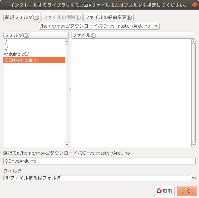
次にライブラリをArduinoに取り込みます。手順は以下の通りです。
スケッチ -> ライブラリのインクルード -> .ZIP形式のライブラリをインストール
Download/ODrive-master/Arduino/ODriveArduino
を選択して、ライブラリをインポートします。
ArduinoとOdriveの動作確認
ArduinoでOdriveを動かすためのサンプルコードが以下にあります。
ファイル -> スケッチ例 -> ODriveArduino -> ODriveArduinoTest
上記ファイルのSet up serial pins to the ODriveコメントでは以下のように使用するArduinoによって設定を変えるよう指示があります。今回はArduino Megaを使用するので、// Arduino Mega or Due - Serial1の部分のコメントを解除して他のArduinoバージョンの設定をコメントアウトします。
////////////////////////////////
// Set up serial pins to the ODrive
////////////////////////////////

// Below are some sample configurations.
// You can comment out the default Teensy one and uncomment the one you wish to use.
// You can of course use something different if you like
// Don't forget to also connect ODrive GND to Arduino GND.

// Teensy 3 and 4 (all versions) - Serial1
// pin 0: RX - connect to ODrive TX
// pin 1: TX - connect to ODrive RX
// See https://www.pjrc.com/teensy/td_uart.html for other options on Teensy
//HardwareSerial& odrive_serial = Serial1;

// Arduino Mega or Due - Serial1
// pin 19: RX - connect to ODrive TX
// pin 18: TX - connect to ODrive RX
// See https://www.arduino.cc/reference/en/language/functions/communication/serial/ for other options
HardwareSerial& odrive_serial = Serial1;

// Arduino without spare serial ports (such as Arduino UNO) have to use software serial.
// Note that this is implemented poorly and can lead to wrong data sent or read.
// pin 8: RX - connect to ODrive TX
// pin 9: TX - connect to ODrive RX
// SoftwareSerial odrive_serial(8, 9);


// ODrive object
ODriveArduino odrive(odrive_serial);
Arduino Megaでは4つのシリアルポート(serial, serial1, serial2, serial3)があり、上記ではserial1を使用する場合の例が記載されています。他のシリアルポートを使用する場合は使用するRX, TXのpin番号が変更します。pin番号については以下の記事を参照してください。
またArduinoのTX pinはGPIO1に、RX pinはGPIO2に挿してください。OdriveはGPIO1, GPIO2を介してArduinoとUART通信を行います。
- Tx of the ODrive <=> Rx of other device
- Rx of the ODrive <=> Tx of other device
- GND of the ODrive (use any GND pin on J3 of the ODrive) <=> GND of the other device
次にArduino側でモータの最大速度や最大電流値の設定をします。
// In this example we set the same parameters to both motors.
// You can of course set them different if you want.
// See the documentation or play around in odrivetool to see the available parameters
for (int axis = 0; axis < 2; ++axis) {
  odrive_serial << "w axis" << axis << ".controller.config.vel_limit " << 10.0f << '\n';
  odrive_serial << "w axis" << axis << ".motor.config.current_lim " << 11.0f << '\n';
  // This ends up writing something like "w axis0.motor.config.current_lim 10.0\n"
}
デフォルトでは最大速度が10.0f、最大電流値が11.0fに設定されていますが、こちらは使用するモータに合わせて適宜調整する必要があります。ちなみにここでは2つのモータを使用することが想定されており、どちらの設定値も同じ値を使用しています。もし片方づつ設定したい場合は、for文は使わずに別々に設定する必要があります。ただし、すでにodrivetool内でconfig設定を行っている場合は上記の処理は不要になります。
またfor loop内で一度キャリブレーションをする部分があります。
    // Run calibration sequence
    if (c == '0' || c == '1') {
      int motornum = c-'0';
      int requested_state;

      requested_state = ODriveArduino::AXIS_STATE_MOTOR_CALIBRATION;
      Serial << "Axis" << c << ": Requesting state " << requested_state << '\n';
      if(!odrive.run_state(motornum, requested_state, true)) return;

      requested_state = ODriveArduino::AXIS_STATE_ENCODER_OFFSET_CALIBRATION;
      Serial << "Axis" << c << ": Requesting state " << requested_state << '\n';
      if(!odrive.run_state(motornum, requested_state, true, 25.0f)) return;

      requested_state = ODriveArduino::AXIS_STATE_CLOSED_LOOP_CONTROL;
      Serial << "Axis" << c << ": Requesting state " << requested_state << '\n';
      if(!odrive.run_state(motornum, requested_state, false /*don't wait*/)) return;
    }
この部分についてもすでにodrivetool内でキャリブレーション内容を保存している場合不要になります。
ただし、requested_state = ODriveArduino::AXIS_STATE_CLOSED_LOOP_CONTROLは設定してあげる必要があります。
ここまで準備が整えばあとは実際にArduinoのシリアルモニタから動作確認を行うだけです!
ArduinoとOdriveによる位置制御
サンプルコードを参考に位置制御に特化したコードを記載します。Arduino側からUART通信を利用してOdriveに指令値を送ります。位置制御の指令値をコマンドは以下の通りです。
- 位置指令値コマンド
odrive.SetPosition(axis, target_position)
第一引数に軸番号を第二引数に目標位置(turn)を設定することで、指令値を送る事が出来ます。
動作確認
それでは以下のコードで位置制御の動作確認を行います。ただし以下のコードは、odrivetool内で最大速度や最大電流値の保存及びキャリブレーションの保存をしていると仮定して書かれています。
# include <HardwareSerial.h>
# include <SoftwareSerial.h>
# include <ODriveArduino.h>
// Printing with stream operator helper functions
template<class T> inline Print& operator <<(Print &obj,     T arg) { obj.print(arg);    return obj; }
template<>        inline Print& operator <<(Print &obj, float arg) { obj.print(arg, 4); return obj; }

////////////////////////////////
// Set up serial pins to the ODrive
////////////////////////////////
// pin 17: RX - connect to ODrive TX GPIO 1
// pin 16: TX - connect to ODrive RX GPIO 2
HardwareSerial& odrive_serial = Serial2;

// ODrive object
ODriveArduino odrive(odrive_serial);

void odrive_calibration()
{
  int motornum0 = 0;
  int motornum1 = 1;
  int requested_state0;
  int requested_state1;

  requested_state0 = ODriveArduino::AXIS_STATE_CLOSED_LOOP_CONTROL;
  if(!odrive.run_state(motornum0, requested_state0, false /*don't wait*/)) return;

  requested_state1 = ODriveArduino::AXIS_STATE_CLOSED_LOOP_CONTROL;
  if(!odrive.run_state(motornum1, requested_state1, false /*don't wait*/)) return;
}

void setup() {
  // ODrive uses 115200 baud
  odrive_serial.begin(115200);

  // Serial to PC
  Serial.begin(115200);
  while (!Serial) ; // wait for Arduino Serial Monitor to open

  odrive_calibration();
  delay(1000);
}

void loop() {
    Serial.println("Executing test position control");
    delay(2000);
    float pos_m0 = 2.0f;
    float pos_m1 = 2.0f;
    odrive.SetPosition(0, pos_m0);
    odrive.SetPosition(1, pos_m1);
}
問題が無ければ以下のように動作すると思います。位置制御の指令値の単位はturnなので、何回転かするとモーターが停止します。

ArduinoとOdriveによる速度制御
次にサンプルコードを参考に速度制御に特化したコードを記載します。Arduino側からUART通信を利用してOdriveに指令値を送ります。速度制御の指令値をコマンドは以下の通りです。
- 速度指令値コマンド
odrive.SetVelocity(axis, target_velocity)
第一引数に軸番号を第二引数に目標速度(turn/s)を設定することで、指令値を送る事が出来ます。
動作確認
それでは以下のコードで速度制御の動作確認を行います。
# include <HardwareSerial.h>
# include <SoftwareSerial.h>
# include <ODriveArduino.h>
// Printing with stream operator helper functions
template<class T> inline Print& operator <<(Print &obj,     T arg) { obj.print(arg);    return obj; }
template<>        inline Print& operator <<(Print &obj, float arg) { obj.print(arg, 4); return obj; }

////////////////////////////////
// Set up serial pins to the ODrive
////////////////////////////////
// pin 17: RX - connect to ODrive TX GPIO 1
// pin 16: TX - connect to ODrive RX GPIO 2
HardwareSerial& odrive_serial = Serial2;

// ODrive object
ODriveArduino odrive(odrive_serial);

void odrive_calibration()
{
  int motornum0 = 0;
  int motornum1 = 1;
  int requested_state0;
  int requested_state1;

  requested_state0 = ODriveArduino::AXIS_STATE_CLOSED_LOOP_CONTROL;
  if(!odrive.run_state(motornum0, requested_state0, false /*don't wait*/)) return;

  requested_state1 = ODriveArduino::AXIS_STATE_CLOSED_LOOP_CONTROL;
  if(!odrive.run_state(motornum1, requested_state1, false /*don't wait*/)) return;
}

void setup() {
  // ODrive uses 115200 baud
  odrive_serial.begin(115200);

  // Serial to PC
  Serial.begin(115200);
  while (!Serial) ; // wait for Arduino Serial Monitor to open

  odrive_calibration();
  delay(1000);
}

void loop() {
    Serial.println("Executing test velocity control");
    delay(2000);
    float vel0 = 2.0f;
    float vel1 = 2.0f;
    odrive.SetVelocity(0, vel0);
    odrive.SetVelocity(1, vel1);
}
問題が無ければ以下のように動作すると思います。速度制御の指令値の単位はturn/sなので、モーターは指令値通りに回り続けます。
まとめ
- OdriveとArduinoを使用してBLDCのモーター制御(位置制御、速度制御)を行いました。
参考文献