NodeMCU v1.0(ESP12-E)を使う
NodeMCUはESP-12Eを搭載したマイコンボードです。
Amica製とLolin製があります。今回はAmica製を使用しています。
QiitaにNodeMCUのリンクがあったので、そちらを紹介しておきます。
https://qiita.com/sugasaki/items/d7d9bef49339f325367b
NodeMCUのドライバのインストール
ProMicroはUSBを刺しただけで認識したのですが、NodeMCUは専用のドライバをインストールする必要があるようです。
https://jp.silabs.com/products/development-tools/software/usb-to-uart-bridge-vcp-drivers
(参考)NodeMCUのGPIOの対応表
D0~D10の範囲でGPIOが使用できます。
NodeMCUのGPIO番号は基板上の値と対応しておらず、自分もよく忘れるので、メモしておきます。
https://github.com/esp8266/Arduino/blob/master/variants/nodemcu/pins_arduino.h#L37-L59
# define D0 16
# define D1 5 // I2C Bus SCL (clock)
# define D2 4 // I2C Bus SDA (data)
# define D3 0
# define D4 2 // Same as "LED_BUILTIN", but inverted logic
# define D5 14 // SPI Bus SCK (clock)
# define D6 12 // SPI Bus MISO
# define D7 13 // SPI Bus MOSI
# define D8 15 // SPI Bus SS (CS)
# define D9 3 // RX0 (Serial console)
# define D10 1 // TX0 (Serial console)
OLEDモジュール(SSD1331)
有機ELを使用したフルカラーLED搭載のOLEDモジュールです。今回は下記のOLEDモジュールを使用しています。
https://www.amazon.co.jp/gp/product/B0711RKXB5/
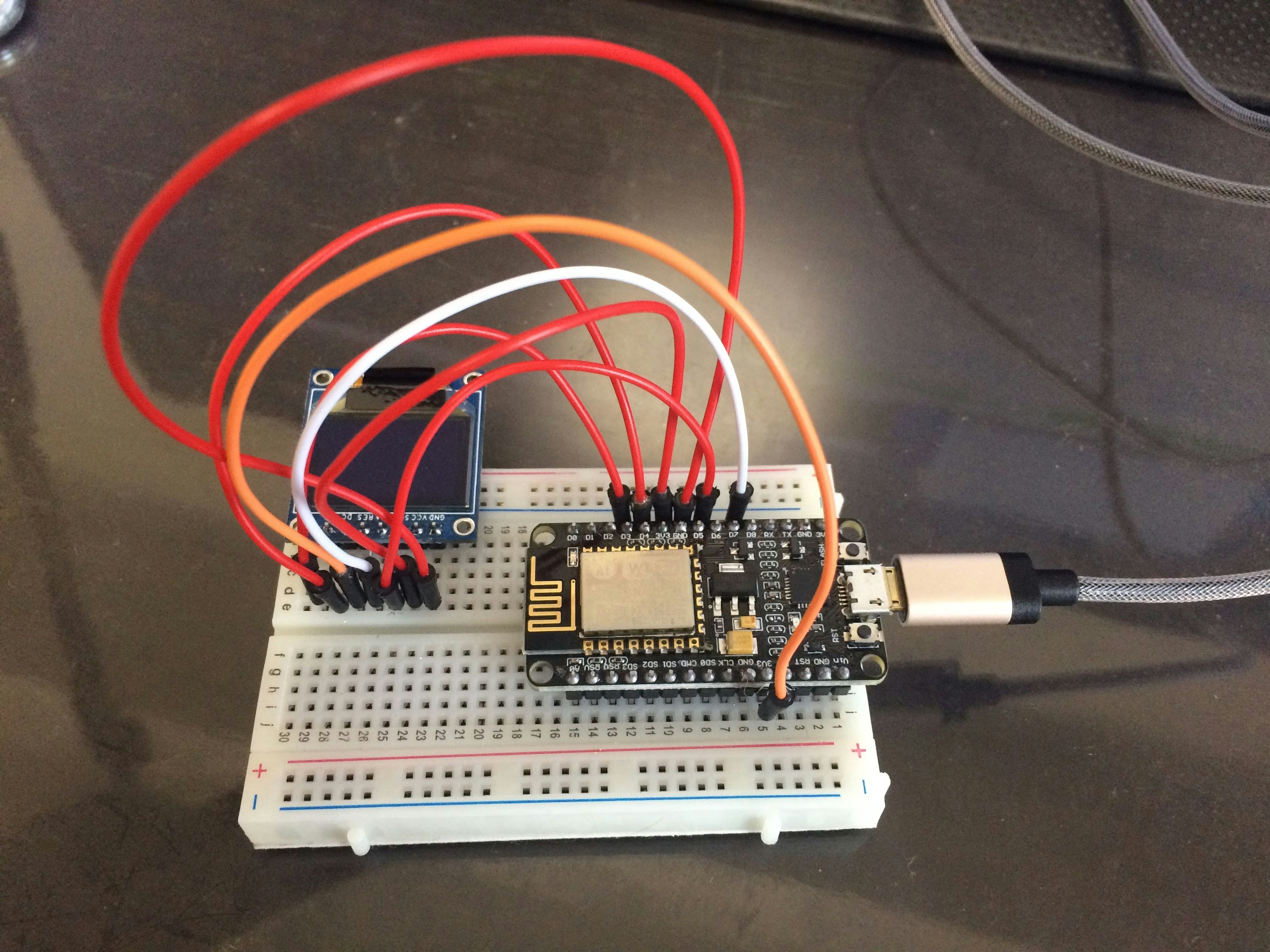
NodeMCUとSSD1331の配線
NodeMCUとSSD1331を接続するときにどのように配線するかは、使用するドライバによって変わります。今回使ったドライバは下記のドライバです。
https://github.com/sumotoy/SSD_13XX
上記のサイトでは以下のように説明されています。
Connections:
Of course some oled has just SPI exposed but some can be configured for parallel, I2C and so on. I'm using ONLY SPI here (so don't ask for any other protocol please).

    RST Connect to +3v3 using a 4k7->10k resistor.
    scl, sclk -> SCLK
    sda, sdin -> MOSI
    DC,RS ->DC pin on MCU
    some oled has WR, RD. Leave floating...
    some oled has D0...D7. Most of the times D0 and D1 are used for SPI, connect D2...D7 to GND or will be unstable!
    VIN. Most oled support 5v, internally they have regulators, but follow specifications of your particular oled!
    3v3. This is 99% of the times an OUT! So do not use it.
つまり、以下のように配線します。
| SSD1331 | NodeMCU |
|---|---|
| GND | GND |
| VCC | 3V3 |
| SCL | D5 |
| SDA | D7 |
| RES | 3V3 |
| DC | D4(ここはプログラム側で指定するので空いているGPIOでよい) |
| CS | D3(ここはプログラム側で指定するので空いているGPIOでよい) |
ネット各所でArduinoとSSD1331の配線を調査していたのですが、10kΩ抵抗を挟むとか、差し込むピンがサイトによってまちまちだったのですが、今回使用したモジュールに関しては内部に既に抵抗が入っていたため、ピンを直接差し込むだけで大丈夫でした。
配線イメージ
サンプルプログラムを書く
ProMicroの時と同様にPlatformIOを使用しています。
https://qiita.com/Kirika/items/f9e9ff21c19f582cba47
プロジェクトの作成
PlatformIO IDEの「New Project」を選択して、Project Wizardに以下を入力。
Name: プロジェクト名。今回はSSD1331_TESTとした。
Board: 接続するボードを選択する。NodeMCU 1.0(ESP-12E Module)
Framework: Arduino
Location: 特に何もなければ「Use default location」を選択.
プロジェクト作成後、今回はライブラリも必要になるためターミナルで以下のコマンドを入力。
platformio lib install "SSD_13xx"
examplesに入っているサンプルプログラムをmain.cppにコピーする
#define __CS1と#define __DCの数値は、実際に接続したピンに対応したGPIOの番号を入力します。
ここではD4とD3につないだので、__CS1を0、__DCを2に設定します。
作成したら「タスクの実行」→「PlatformIO: Upload」を実行して、プログラムを書き込みます。
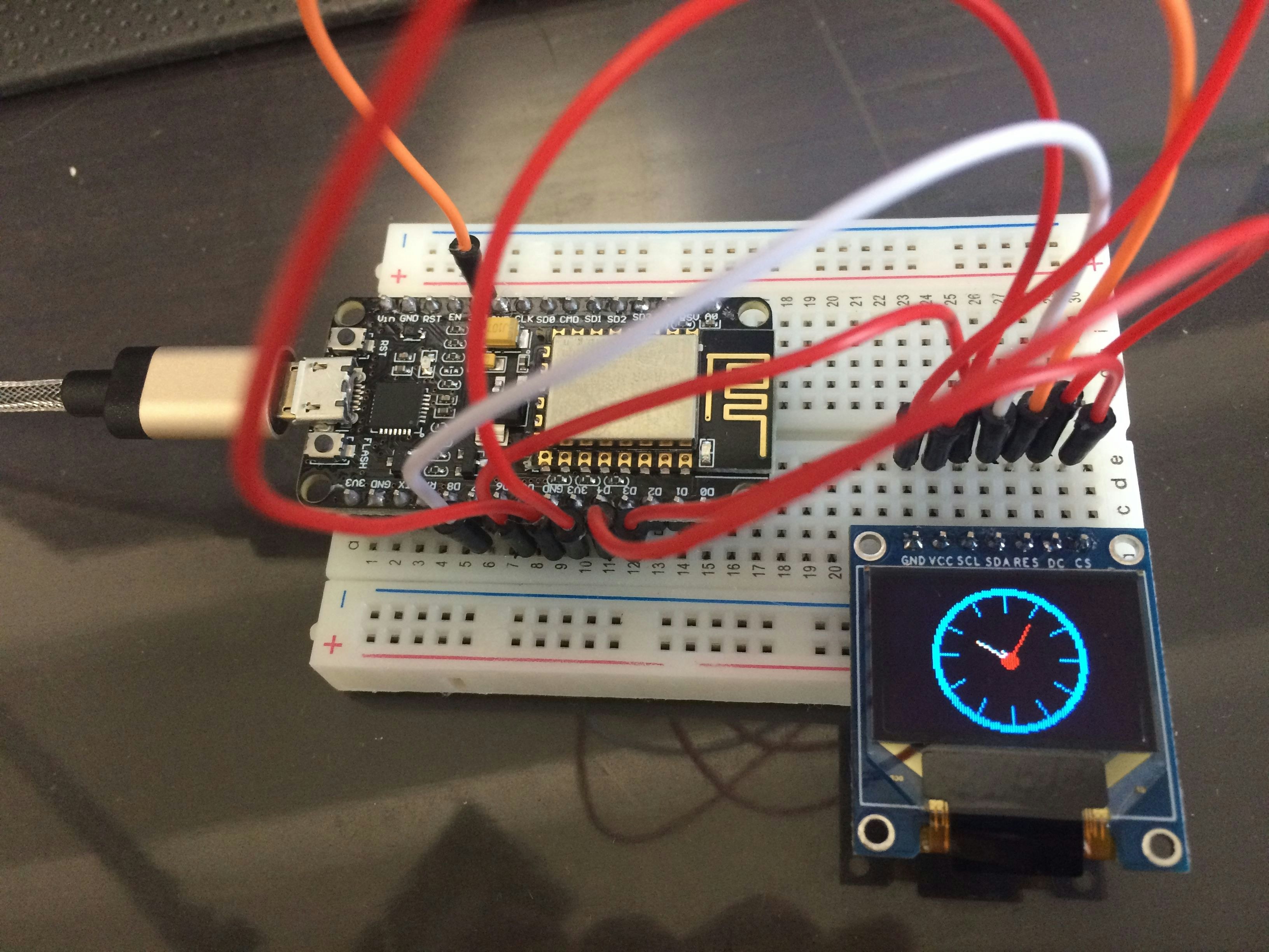
実際の動作
全くの手探りで進めましたが、いざLEDに表示されると興奮しますね!

