Pybulletでロボットを動かす
前回の記事では手動でのロボットアームの動かし方を紹介しました。
しかし、実際のロボットは作業を自動化していることが多いです。なので今回の記事ではロボットを自動で動かすための第一歩、順運動学を解説していきます。
手動でのロボットの動かし方やPybulletの基礎について知りたいという方は前回の記事をご覧ください。
また、逆運動学について知りたい方は、こちらの記事をご覧ください。逆運動学の数値解法について解説しています。
動作環境
-
Windows10
-
WSL2
-
Ubunu18.04
順運動学と逆運動学
ロボットをプログラム的に動かすには、順運動学と逆運動学が必要になります。
順運動学
ロボットアームの各関節角度からアームの手先座標を求める
逆運動学
任意の座標を指定したとき、手先アームがそこに辿り着くための各関節角度を求める
つまり、順運動学が計算できれば関節角度からロボットの手先などの位置と方向が分かり、逆運動学が計算できれば目的とする手先の位置と方向を実現するための姿勢をとらせることができるということです。
例えば、ロボットアームを使ってモノを掴んだり、ドアを開けたり、ボタンを押したりするためには、そのロボットアームの順運動学と逆運動学を知る必要があります。
また、逆運動学を解くためには順運動学が必要になるので、ロボットを動かしたいならまず順運動学を理解することが第一でしょう。
順運動学の求め方
ロボットアームの選択
ロボットアームの順運動学を解くためには、アームの長さを知っている必要があります。なので使いたいロボットアームがある場合は、そのアームの寸法を調べておきましょう。
今回は例としてデンソーのVS-068というロボットアームを使わせていただくことにしました。このロボットアームは自由度6の垂直多関節アームなので、関節が6か所あります。
まずはVS-068の寸法図を基にロボットアームのURDFを自作しました。
VS-068のURDF
このロボットアームのURDFは以下に貼っておきますので、必要に応じてこのコードをコピペして下さい。
VS-068.urdf (クリックして表示)
<?xml version="1.0"?>
<robot name="vs-068">
  <link name="base">
    <inertial>
      <origin rpy = "0 0 0" xyz = "0 0 0" />
      <mass value = "0.0001" />
      <inertia ixx = "0.0001" ixy = "0" ixz = "0" iyy = "0.0001" iyz = "0" izz = "0.0001" />
    </inertial>
  </link>
  <link name="stand">
    <contact>
      <lateral_friction value = "100" />
    </contact>
    <inertial>
      <origin rpy = "0 0 0" xyz = "0.000 0.000 0.09875" />
        <mass value = "5000" />
        <inertia ixx = "54.5" ixy = "0" ixz = "0" iyy = "54.5" iyz = "0" izz = "76.6" />
    </inertial>
    <visual>
      <origin rpy="0 0 0" xyz="0 0 0.09875"/>
      <geometry>
        <cylinder radius="0.175" length="0.1975"/>
      </geometry>
      <material name="Gray">
        <color rgba="0.8 0.8 0.8 1" />
      </material>
    </visual>
    <collision>
      <origin rpy = "0 0 0" xyz = "0.000 0.000 0.09875" />
      <geometry>
        <cylinder radius="0.175" length="0.1975"/>
      </geometry>
    </collision>
  </link>
  <joint name="base_stand" type="fixed" >
    <parent link = "base" />
    <child link = "stand" />
    <origin rpy = "0 0 0" xyz = "0.000 0.000 0.000" />
  </joint>
  <link name="arm1">
    <inertial>
      <origin rpy = "0 0 0" xyz = "0.000 -0.015 0.12875" />
        <mass value = "7.5" />
        <inertia ixx = "0.066441" ixy = "0" ixz = "0" iyy = "0.075957" iyz = "0" izz = "0.059516" />
    </inertial>
    <visual>
      <origin rpy="0 0 0" xyz="0 -0.015 0.12875"/>
      <geometry>
        <box size="0.235 0.20 0.2575"/>
      </geometry>
      <material name="Gray">
      </material>
    </visual>
    <collision>
      <origin rpy = "0 0 0" xyz = "0.000 -0.015 0.12875" />
      <geometry>
        <box size = "0.235 0.20 0.2575" />
      </geometry>
    </collision>
  </link>
  <joint name="stand_arm1" type="revolute" >
    <parent link = "stand" />
    <child link = "arm1" />
    <origin rpt = "0 0 0" xyz = "0 0 0.1975" />
    <axis xyz = "0 0 1" />
    <limit effort="10000.0" lower="-2.96705972839036" upper="2.96705972839036" velocity="3.15"/>
  </joint>
  <link name="arm2">
    <inertial>
      <origin rpy = "0 0 0" xyz = "0.000 0.000 0.17" />
        <mass value = "10" />
        <inertia ixx = "0.17333" ixy = "0" ixz = "0" iyy = "0.18008" iyz = "0" izz = "0.03075" />
    </inertial>
    <visual>
      <origin rpy="0 0 0" xyz="0 0 0.17"/>
      <geometry>
        <box size="0.15 0.120 0.44"/>
      </geometry>
      <material name="Gray">
      </material>
    </visual>
    <collision>
      <origin rpy = "0 0 0" xyz = "0.000 0.000 0.17" />
      <geometry>
        <box size = "0.15 0.120 0.44" />
      </geometry>
    </collision>
  </link>
  <joint name="arm1_arm2" type="revolute" >
    <parent link = "arm1" />
    <child link = "arm2" />
    <origin rpy = "0 0 0" xyz = "0.000 -0.03 0.1975" />
    <limit effort="10000.0" lower="-1.7453292519943295" upper="2.356194490192345" velocity="3.15"/>
  </joint>
  <link name="arm3">
    <inertial>
      <origin rpy = "0 0 0" xyz = "0.000 0.000 0.0735" />
        <mass value = "7.5" />
        <inertia ixx = "0.044381" ixy = "0" ixz = "0" iyy = "0.044381" iyz = "0" izz = "0.01250" />
    </inertial>
    <visual>
      <origin rpy="0 0 0" xyz="0 0 0.0735"/>
      <geometry>
        <box size="0.1 0.1 0.247"/>
      </geometry>
      <material name="Gray">
      </material>
    </visual>
    <collision>
      <origin rpy = "0 0 0" xyz = "0.000 0.000 0.197" />
      <geometry>
        <box size = "0.1 0.1 0.247" />
      </geometry>
    </collision>
  </link>
  <joint name="arm2_arm3" type="revolute" >
    <parent link = "arm2" />
    <child link = "arm3" />
    <origin rpy = "1.5707963267948966 0 0" xyz = "0.000 0.000 0.34" />
    <limit effort="10000.0" lower="-3.6651914291880923" upper="1.0995574287564276" velocity="3.15"/>
  </joint>
  <link name="arm4">
    <inertial>
      <origin rpy = "0 0 0" xyz = "0.000 0.000 0.080" />
        <mass value = "5" />
        <inertia ixx = "0.014833" ixy = "0" ixz = "0" iyy = "0.014833" iyz = "0" izz = "0.0083333" />
    </inertial>
    <visual>
      <origin rpy="0 0 0" xyz="0 0 0.080"/>
      <geometry>
        <box size="0.1 0.1 0.160"/>
      </geometry>
      <material name="Gray">
      </material>
    </visual>
    <collision>
      <origin rpy = "0 0 0" xyz = "0.000 0.000 0.08" />
      <geometry>
        <box size = "0.10 0.10 0.16" />
      </geometry>
    </collision>
  </link>
  <joint name="arm3_arm4" type="revolute" >
    <parent link = "arm3" />
    <child link = "arm4" />
    <axis xyz="0 0 1"/>
    <origin rpy = "0 0 0" xyz = "0.000 0.000 0.197" />
    <limit effort="10000.0" lower="-4.71238898038469" upper="4.71238898038469" velocity="3.15"/>
  </joint>
  <link name="arm5">
    <inertial>
      <origin rpy = "0 0 0" xyz = "0.000 0.000 0.03" />
        <mass value = "2.5" />
        <inertia ixx = "0.0020833" ixy = "0" ixz = "0" iyy = "0.0015208" iyz = "0" izz = "0.00093750" />
    </inertial>
    <visual>
      <origin rpy="0 0 0" xyz="0 0 0.03"/>
      <geometry>
        <box size="0.03 0.06 0.08"/>
      </geometry>
      <material name="Black">
        <color rgba="0.3 0.3 0.3 1" />
      </material>
    </visual>
    <collision>
      <origin rpy = "0 0 0" xyz = "0.000 0.000 0.03" />
      <geometry>
        <box size = "0.03 0.06 0.08" />
      </geometry>
    </collision>
  </link>
  <joint name="arm4_arm5" type="revolute" >
    <parent link = "arm4" />
    <child link = "arm5" />
    <origin rpy = "1.5707963267948966 0 0" xyz = "0.000 0.000 0.143" />
    <limit effort="10000.0" lower="-2.0943951023931953" upper="2.0943951023931953" velocity="3.15"/>
  </joint>
  <link name="arm6">
    <inertial>
      <origin rpy = "0 0 0" xyz = "0.000 0.000 0.005" />
        <mass value = "0.5" />
        <inertia ixx = "0.000032292" ixy = "0" ixz = "0" iyy = "0.000032292" iyz = "0" izz = "0.00005625" />
    </inertial>
    <visual>
      <origin rpy="0 0 0" xyz="0 0 0.005"/>
      <geometry>
        <cylinder radius="0.015" length="0.01"/>
      </geometry>
      <material name="Black">
      </material>
    </visual>
    <collision>
      <origin rpy = "0 0 0" xyz="0 0 0.005"/>
      <geometry>
        <cylinder radius="0.015" length="0.01"/>
      </geometry>
    </collision>
  </link>
  <joint name="arm5_arm6" type="revolute" >
    <parent link = "arm5" />
    <child link = "arm6" />
    <origin rpy = "0 0 0" xyz = "0.000 0.000 0.07" />
    <axis xyz="0 0 1"/>
    <limit effort="10000.0" lower="-3.141592653589793" upper="3.141592653589793" velocity="3.15"/>
  </joint>
  <link name="gripper1">
    <inertial>
      <origin rpy = "0 0 0" xyz = "0.000 0.000 0.005" />
        <mass value = "0.020" />
        <inertia ixx = "0.01" ixy = "0" ixz = "0" iyy = "0.01" iyz = "0" izz = "0.01" />
    </inertial>
    <visual>
      <origin rpy="0 0 0" xyz="0 0 0.005"/>
      <geometry>
        <box size="0.04 0.01 0.01"/>
      </geometry>
      <material name="Black">
      </material>
    </visual>
    <collision>
      <origin rpy = "0 0 0" xyz = "0.000 0.000 0.005" />
      <geometry>
        <box size = "0.04 0.01 0.010" />
      </geometry>
    </collision>
  </link>
  <joint name="arm6_gripper1" type="fixed" >
    <parent link = "arm6" />
    <child link = "gripper1" />
    <origin rpy = "0 0 0" xyz = "0.000 0.000 0.010" />
  </joint>
  <link name="gripper2">
    <contact>
      <lateral_friction value = "10" />
    </contact>
    <inertial>
      <origin rpy = "0 0 0" xyz = "0.000 0.000 0.0075" />
        <mass value = "0.003" />
        <inertia ixx = "0.01" ixy = "0" ixz = "0" iyy = "0.005" iyz = "0" izz = "0.005" />
    </inertial>
    <visual>
      <origin rpy="0 0 0" xyz="0 0 0.0075"/>
      <geometry>
        <box size="0.005 0.01 0.015"/>
      </geometry>
      <material name="Black">
      </material>
    </visual>
    <collision>
      <origin rpy = "0 0 0" xyz = "0.000 0.000 0.0075" />
      <geometry>
        <box size = "0.005 0.010 0.015" />
      </geometry>
    </collision>
  </link>
  <joint name="gripper1_gripper2" type="prismatic" >
    <parent link = "gripper1" />
    <child link = "gripper2" />
    <origin rpy = "0 0 0" xyz = "-0.0175 0.000 0.01" />
    <limit effort="10000.0" lower="0" upper="0.015" velocity="0.5"/>
  </joint>
  <link name="gripper3">
    <contact>
      <lateral_friction value = "10" />
    </contact>
    <inertial>
      <origin rpy = "0 0 0" xyz = "0.000 0.000 0.0075" />
        <mass value = "0.003" />
        <inertia ixx = "0.01" ixy = "0" ixz = "0" iyy = "0.005" iyz = "0" izz = "0.005" />
    </inertial>
    <visual>
      <origin rpy="0 0 0" xyz="0 0 0.0075"/>
      <geometry>
        <box size="0.005 0.01 0.015"/>
      </geometry>
      <material name="Black">
      </material>
    </visual>
    <collision>
      <origin rpy = "0 0 0" xyz = "0.000 0.000 0.0075" />
      <geometry>
        <box size = "0.005 0.010 0.015" />
      </geometry>
    </collision>
  </link>
  <joint name="gripper1_gripper3" type="prismatic" >
    <parent link = "gripper1" />
    <child link = "gripper3" />
    <origin rpy = "0 0 0" xyz = "0.0175 0.000 0.01" />
    <limit effort="10000.0" lower="-0.015" upper="0" velocity="0.5"/>
  </joint>
</robot>
VS-068の関節構造
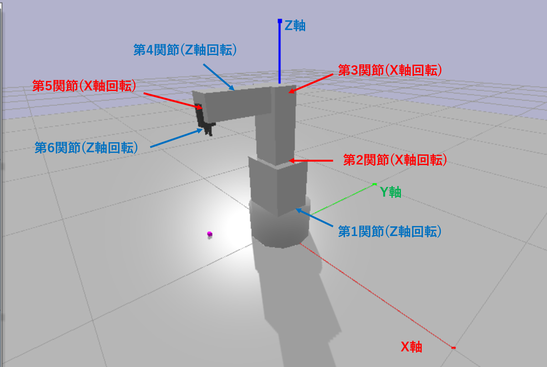
このロボットアームの各関節についてまとめるとこんな感じです。
| 関節 | 回転軸 | 可動範囲 θ | 備考 |
|---|---|---|---|
| 1 | Z軸 | $-170° ≤ θ_1 ≤ 170°$ | |
| 2 | X軸 | $-100° ≤ θ_2 ≤ 135°$ | |
| 3 | X軸 | $-120° ≤ θ_3 ≤ 153°$ | 初期関節角度 $θ_0$ = 90° |
| 4 | Z軸 | $-270° ≤ θ_4 ≤ 270°$ | わかりずらいですが図の位置に関節があります。 |
| 5 | X軸 | $-120° ≤ θ_5 ≤ 120°$ | 初期関節角度 $θ_0$ = 90° |
| 6 | Z軸 | $-360° ≤ θ_6 ≤ 360°$ | 手先の部分がくるくる回転します。 |
順運動学を解くときに第2関節と第5関節が最初から直角に曲がっていることに注意が必要です。
VS-068のアーム構造
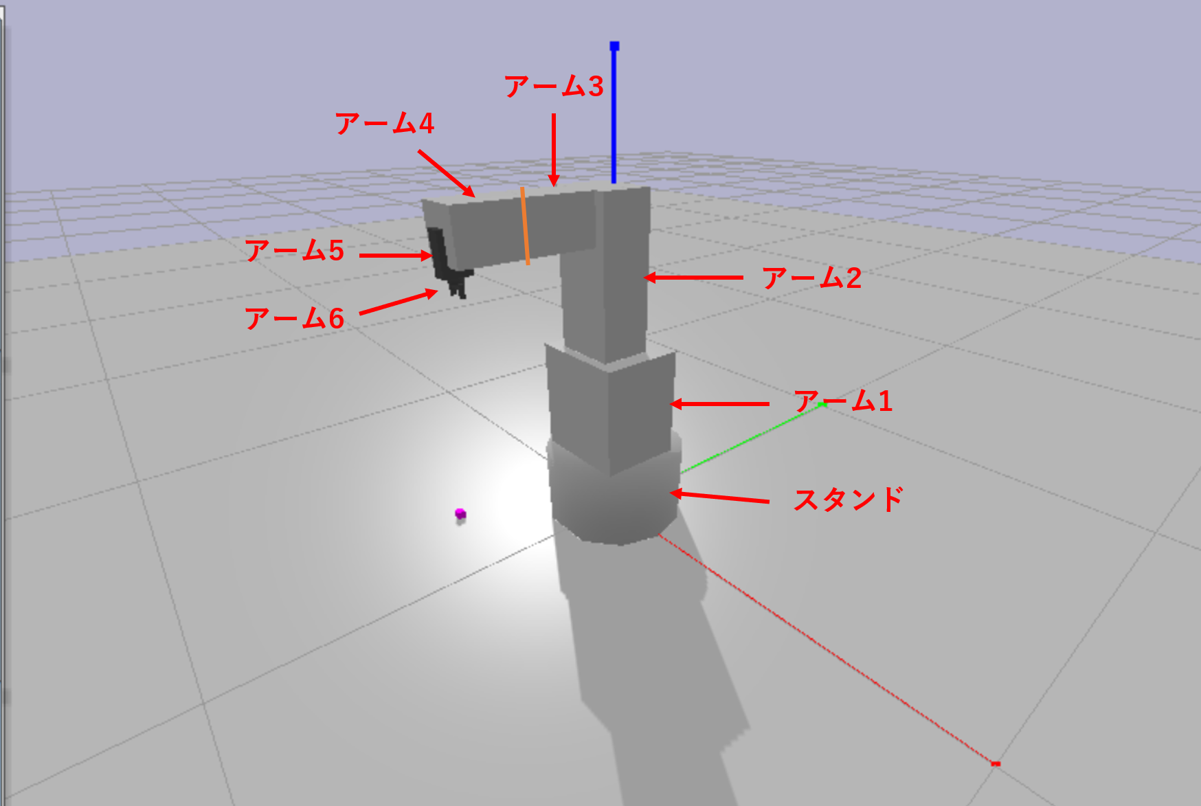
各アームの寸法についてはこんな感じです。
| アーム | 長さ L [m] | 備考 |
|---|---|---|
| スタンド | $0.1975$ | |
| 1 | $0.1975$ | |
| 2 | $0.34$ | アーム1の先端からY軸方向に-0.03 [m] 位置がずれている |
| 3 | $0.197$ | 画像のオレンジ線の右側までがアーム3 |
| 4 | $0.143$ | 画像のオレンジ線の左側からがアーム4 |
| 5 | $0.07$ | |
| 6 | $0.035$ | アームとグリッパーを合わせた長さ |
順運動学を解くときにアーム1とアーム2の間で少しY軸方向にずれていることに注意が必要です。
順運動学を解く
さて、ロボットアームの寸法が分かったので順運動学を解いていきます。
結果を言ってしまえば、順運動学は回転行列という行列をかけることで簡単に導くことができます。回転行列の詳細についてはこちらの記事などが参考になると思います。
回転行列を用いれば順運動学を解くことができ、ロボットアームの手先座標や手先姿勢を得ることができます。
ちなみに、順運動学による手先姿勢の表現方法については回転行列の他にもオイラー角やクォータニオンを用いた方法などがあるので、目的によって使い分けられると良いでしょう。
3次元の回転行列は3×3ですが、これに平行移動の要素も追加して4×4の行列(同次座標変換行列)にします。
ロボットアームの長さ (平行移動の要素) を
L = (L_x, L_y, L_z)
とすると、アームの長さ L だけ平行移動させたあと、各軸まわりに θ だけ回転させる回転行列は以下のように表すことができます。
T_x = \left(
    \begin{array}{ccc}
      1 & 0 & 0 & L_x \\
      0 & cosθ & -sinθ & L_y \\
      0 & sinθ & cosθ & L_z \\
      0 & 0 & 0 & 1 \\
    \end{array}
  \right)
\
T_y = \left(
    \begin{array}{ccc}
      cosθ & 0 & sinθ & L_x \\
      0 & 1 & 0 & L_y \\
      -sinθ & 0 & cosθ & L_z \\
      0 & 0 & 0 & 1 \\
    \end{array}
  \right)
\
T_z = \left(
    \begin{array}{ccc}
      cosθ & -sinθ & 0 & L_x \\
      sinθ & cosθ & 0 & L_y \\
      0 & 0 & 1 & L_z \\
      0 & 0 & 0 & 1 \\
    \end{array}
  \right)
難しく見えますが、この回転行列を順番にかけることで順運動学を解くことができます。
これを実際にPythonで記述してみると以下のようになります。
import math
import numpy as np

# 各アームの長さLとジョイントの角度θを入力に手先座標[x, y, z]を出力する関数
def forwardKinematics3D(L, js):
  Ts = [] #各回転行列Tを収めるリスト

  #各ジョイントのsin, cosを計算
  c0 = math.cos(js[0])
  s0 = math.sin(js[0])
  c1 = math.cos(js[1])
  s1 = math.sin(js[1])
  c2 = math.cos(js[2])
  s2 = math.sin(js[2])
  c3 = math.cos(js[3])
  s3 = math.sin(js[3])
  c4 = math.cos(js[4])
  s4 = math.sin(js[4])
  c5 = math.cos(js[5])
  s5 = math.sin(js[5])

  #各回転行列Tを計算
  #スタンド先端までの回転行列T0
  Ts.append(np.matrix([[c0, -s0, 0, 0], [s0, c0, 0, 0], [0, 0, 1, L[0]], [0, 0, 0, 1]]))
  #アーム1先端までの回転行列T1
  Ts.append(np.matrix([[1, 0, 0, 0], [0, c1, -s1, -0.03], [0, s1, c1, L[1]], [0, 0, 0, 1]]))
  #アーム2先端までの回転行列T2
  Ts.append(np.matrix([[1, 0, 0, 0], [0, c2, -s2, 0], [0, s2, c2, L[2]], [0, 0, 0, 1]]))
  #アーム3先端までの回転行列T3
  Ts.append(np.matrix([[c3, -s3, 0, 0], [s3, c3, 0, 0], [0, 0, 1, L[3]], [0, 0, 0, 1]]))
  #アーム4先端までの回転行列T4
  Ts.append(np.matrix([[1, 0, 0, 0], [0, c4, -s4, 0], [0, s4, c4, L[4]], [0, 0, 0, 1]]))
  #アーム5先端までの回転行列T5
  Ts.append(np.matrix([[c5, -s5, 0, 0], [s5, c5, 0, 0], [0, 0, 1, L[5]], [0, 0, 0, 1]]))
  #アーム6先端までの回転行列T6
  Ts.append(np.matrix([[1, 0, 0, 0], [0, 1, 0, 0], [0, 0, 1, L[6]], [0, 0, 0, 1]]))

  #各回転行列をかけ合わせることでアーム6の手先座標を求める純運動学を解く
  TTs = Ts[0]*Ts[1]*Ts[2]*Ts[3]*Ts[4]*Ts[5]*Ts[6]

  #手先座標[x, y, z]を出力
  return [TTs[0, 3], TTs[1, 3], TTs[2, 3]]
アームは全てZ軸方向に真っ直ぐ伸びているため、$L_x, L_y = 0$ となっています。
ただ、T1だけはY軸方向に -0.03 [m] ずれているため、$L_y = -0.03$ となっています。
では、実際に実行してみましょう。
L = [0.1975, 0.1975, 0.34, 0.197, 0.143, 0.07, 0.035] #各アームの長さ
js1 = [0, 0, 0, 0, 0, 0] #各関節角度を設定 (値は関節の動作範囲内で適当に設定)
js2 = [math.pi*45/180, 0, math.pi*90/180, 0, math.pi*90/180, 0] #関節角度を変えたパターン
print("[x, y, z] =", forwardKinematics3D(L, js1)) #順運動学を解いて手先座標を出力 (js1)
print("[x, y, z] =", forwardKinematics3D(L, js2)) #順運動学を解いて手先座標を出力 (js2)
実行結果
[x, y, z] = [0.0, -0.03, 1.1800000000000002]
[x, y, z] = [0.2616295090390226, -0.2616295090390226, 0.63]
Pybulletで動作確認
順運動学は無事解くことができたので、あとはPybulletを使ったシミュレーション環境でこれを動かしてみましょう。
import pybullet as p
import time
import math
import numpy as np
import getPosition as gp

p.connect(p.GUI)
robot = p.loadURDF("vs_068.urdf", [0, 0, 0], useFixedBase=True)
p.loadURDF("plane.urdf", [0, 0, 0], useFixedBase=True)

L = [0.1975, 0.1975, 0.34, 0.197, 0.143, 0.07, 0.035]
targetPos=[0 for i in range(6)]

gravId = p.addUserDebugParameter("gravity", -10, 10, -10)
jointIds = []
paramIds = []

p.setPhysicsEngineParameter(numSolverIterations=10)
p.changeDynamics(robot, -1, linearDamping=0, angularDamping=0)

for j in range(p.getNumJoints(robot)):
  p.changeDynamics(robot, j, linearDamping=0, angularDamping=0)
  info = p.getJointInfo(robot, j)
  jointName = info[1]
  jointType = info[2]
  if (jointType == p.JOINT_PRISMATIC or jointType == p.JOINT_REVOLUTE):
    jointIds.append(j)
    paramIds.append(p.addUserDebugParameter(jointName.decode("utf-8"), -4, 4, 0))

time_count=0

p.setRealTimeSimulation(1)
while (1):
  p.setGravity(0, 0, p.readUserDebugParameter(gravId))
  for i in range(6):
    targetPos[i] = p.readUserDebugParameter(paramIds[i])
    p.setJointMotorControl2(robot, jointIds[i], p.POSITION_CONTROL, targetPos[i], force=5 * 240.)

  if time_count%10==0:
    js = [targetPos[0], targetPos[1], targetPos[2]+math.pi/2, targetPos[3], targetPos[4]+math.pi/2, targetPos[5]]
    print(gp.forwardKinematics3D(L, js))

  time_count+=1
  time.sleep(0.01)
注意点として、このコードを実行するには 「vs_068.urdf ファイル、 plane.urdf ファイル、 plane100.obj」 の3つをforwardKinematicsSimulation.py と同じディレクトリ内に入れておく必要があります。
plane.urdf と plane100.obj についてはPybulletインストール時に同封されています。
vs_068.urdf についてはこの記事の上部にURDFを載せているので、そちらをコピペして下さい。
実行結果
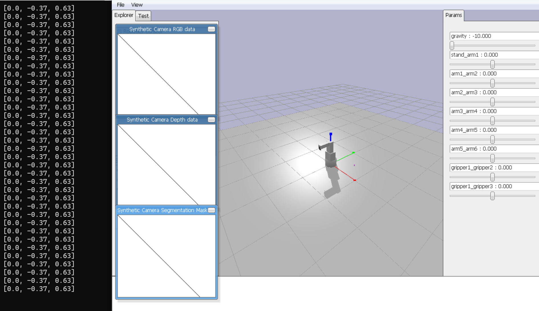
シミュレーション中に手先座標がリアルタイムで表示されます。(画像左)
画像右のバーでジョイントのパラメータを動かすと、それに応じて表示される手先角度も変化します。
最後に
この記事は早稲田大学の尾形研究室での活動の一環として書きました。
ロボットや深層学習について研究しているので、興味のある方は以下の研究室HPをご覧下さい。