動作環境
Ubuntu 18.04 LTS
ボード: STM32F769 Discovery Kit (以下、STM32F769)
Zephyr 2.1.0-rc1
SRAM: 23K256
概要
- Zephyrを使ったSPI通信の実装 (write, read)
- SRAM 23K256に対して書いた値を読み出す
- byte mode
関連資料
- https://www.microchip.com/wwwproducts/en/23K256
- Application Note: AN1245 Recommended Usage of Microchip SPI Serial SRAM Devices
回路図
-
こちらに掲載の回路を使っている
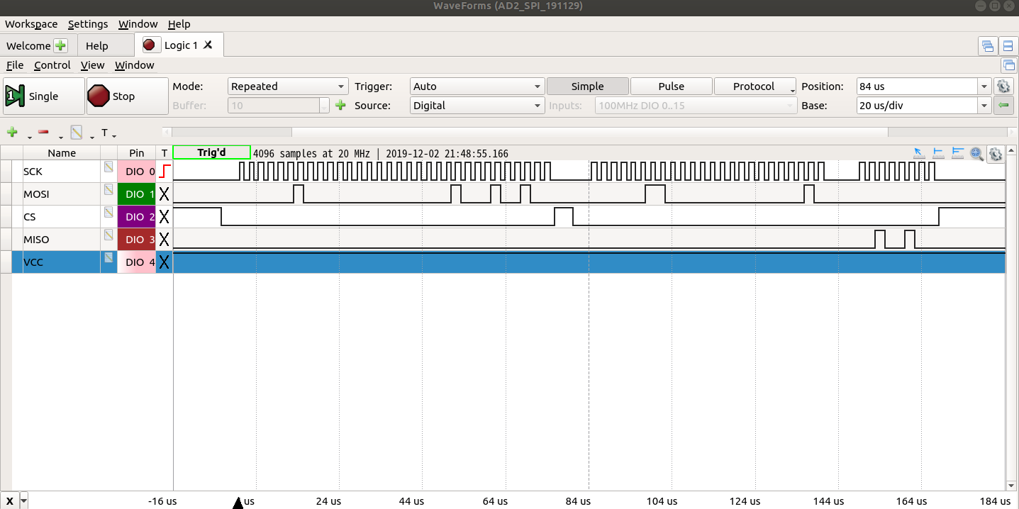
- Analog Discovery 2でモニタをした状態
実装
prj.conf
CONFIG_STDOUT_CONSOLE=y
CONFIG_FLASH=y
CONFIG_SPI=y
# CONFIG_SPI_1=y
CONFIG_SPI_2=y
# CONFIG_SPI_3=y
# CONFIG_SPI_ASYNC=y
main.c
# include <zephyr.h>
# include <device.h>
# include <stdio.h>
# include <spi.h>
# include <misc/printk.h>
# include <errno.h>
# include <stdint.h>

# define CODE_WRITE (0x02)
# define CODE_READ (0x03)
# define CODE_RDSR (0x05)
# define CODE_WRSR (0x01)
# define TARGET_ADR_H (0x00)
# define TARGET_ADR_L (0x02)

static int my_spi_write(struct device *spi, struct spi_config *spi_cfg,
			    u8_t *txbuf, int txlen, u8_t *rxbuf, int rxlen)
{
	struct spi_buf spi_txbufs[] = {
		{
			.buf = txbuf,
			.len = txlen
		}
	};
	struct spi_buf_set tx = {
		.buffers = spi_txbufs,
		.count = 1
	};

	return spi_write(spi, spi_cfg, &tx);
}

static int my_spi_read(struct device *spi, struct spi_config *spi_cfg,
			    u8_t *txbuf, int txlen, u8_t *rxbuf, int rxlen)
{
	struct spi_buf spi_rxbufs[] = {
		{
			.buf = rxbuf,
			.len = rxlen
		}
	};
	struct spi_buf_set rx = {
		.buffers = spi_rxbufs,
		.count = 1
	};

	return spi_read(spi, spi_cfg, &rx);
}

void main(void)
{
	struct device *spi;
	struct spi_config spi_cfg;
	struct spi_cs_control spi_cs;
	int err, idx;

	spi = device_get_binding("SPI_2");  // STM32F769I-Discovery
	if (spi == NULL) {
		printk("SPI_2 not found\n");
		return;
	}
	spi_cfg.operation = SPI_WORD_SET(8);
	spi_cfg.frequency = 500000; // 5000000;
 	// PA11
	spi_cs.gpio_dev = device_get_binding("GPIOA");
	spi_cs.gpio_pin = 11;
	spi_cs.delay = 0;

	spi_cfg.cs = &spi_cs;

	k_sleep(1);

	uint8_t txbufs[10] = {0};
	txbufs[0] = CODE_WRITE;
	txbufs[1] = TARGET_ADR_H;
	txbufs[2] = TARGET_ADR_L;
	txbufs[3] = 0x00;
	uint8_t rxbufs[10] = {0};

	while(1) {
		for(idx=0; idx<16; idx++) {
			// data to be written and read
			txbufs[3] += 0x0C;
			// write
			txbufs[0] = CODE_WRITE;
			spi_cfg.operation = SPI_WORD_SET(8);
			err = my_spi_write(spi, &spi_cfg, txbufs, 4, rxbufs, 0);
			// read
			txbufs[0] = CODE_READ;
			spi_cfg.operation = SPI_WORD_SET(8) | SPI_HOLD_ON_CS;
			err = my_spi_write(spi, &spi_cfg, txbufs, 3, rxbufs, 0);
			spi_cfg.operation = SPI_WORD_SET(8);
			err = my_spi_read(spi, &spi_cfg, txbufs, 0, rxbufs, 1);
			printk("%d: SPI OUTPUT 0x%02X\r\n", err, txbufs[3]);
			printk("%d: SPI INPUT 0x%02X\n", err, rxbufs[0]);
			k_sleep(1000); // msec
		}
	}
 }
実行例
$ west build -p auto -b stm32f769i_disco samples/drivers/wrk_23K256SRAM_191128/
$ west flash
以下はsudo screen /dev/ttyACM0 115200した結果。
0: SPI OUTPUT 0x10
0: SPI INPUT 0x10
0: SPI OUTPUT 0x1c
0: SPI INPUT 0x1c
0: SPI OUTPUT 0x28
0: SPI INPUT 0x28
0: SPI OUTPUT 0x34
0: SPI INPUT 0x34
0: SPI OUTPUT 0x40
0: SPI INPUT 0x40
0: SPI OUTPUT 0x4c
0: SPI INPUT 0x4c
0: SPI OUTPUT 0x58
0: SPI INPUT 0x58
書いた値がそのまま読まれている。
SPI通信を実装できた。
Analog Discovery 2のロジックモニタの様子。
はまった
23K256の読書に関しては文字化けが発生していた。