動作環境
Windows 10 Pro v1909
Arduino IDE v1.8.13
Analog Discovery 2
Arduino Leonardo
概要
- GPIOの状態をロギングしたい
- GPIOの状態をシリアル出力する機能をLeonardo向けに実装した
- Digital Pin 2..9の読み取り
GPIO
画像の右下のDigital Pin 2..9を使用する。
AD2と接続
動作確認はAD2の電圧出力(Supplies)を使用した。オープンピンは誤読を起こすため、電圧出力以外のピンはGNDに接続すること。
(実際の使用ではケーブルが接続されるので、オープンピンにはならない。使うピン数だけの実装にTable_pins[]を変更して使う)。
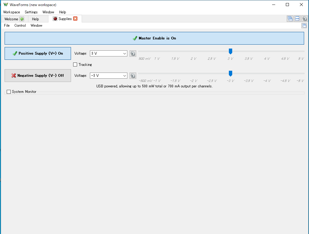
AD2の方では以下のようにPosivitve Supplyを3Vとして使用した (3.3V駆動のMCUのGPIO読み取りに使う)。
Master Enable is OnのボタンをON/OFFして電圧をH/Lに変更する。
実装
# include <TimeLib.h>  // installed Time by Michael Margolis

/*
 * 2020-08-19
 * Digital Pinのシリアル出力
 *   出力例: 2020/08/19,12:30:45,1,0,1,0,1,1,1
 *
 * Digital PinのRX, TXを飛ばして、2..9のピンを使う
 * オープン状態にすると誤読を生じるので、実際に接続するピンだけをTable_p[]で定義すること
 */
# define PIN_DIGPIN2 (2)  // Pin 19
# define PIN_DIGPIN3 (3)  // Pin 18
# define PIN_DIGPIN4 (4)  // Pin 25
# define PIN_DIGPIN5 (5)  // Pin 31
# define PIN_DIGPIN6 (6)  // Pin 27
# define PIN_DIGPIN7 (7)  // Pin 1
# define PIN_DIGPIN8 (8)  // Pin 28
# define PIN_DIGPIN9 (9)  // Pin 29

int Table_pins[] = {
  PIN_DIGPIN2, PIN_DIGPIN3, PIN_DIGPIN4,PIN_DIGPIN5, PIN_DIGPIN6,
  PIN_DIGPIN7, PIN_DIGPIN8, PIN_DIGPIN9,
};
int tableSize;

void setup() {
  Serial.begin(9600);
  tableSize = sizeof(Table_pins) / sizeof(Table_pins[0]);
  for(int idx=0; idx < tableSize; idx++) {
    pinMode(Table_pins[idx], INPUT);
  }
}

void myPrintf(char *fmt, ...)
{
  char buf[128];
  va_list args;
  va_start(args, fmt);
  vsnprintf(buf, 128, fmt, args);
  va_end(args);
  Serial.print(buf);
}

void loop() {
  int val;

  myPrintf("%04d/%02d/%02d,", year(), month(), day(), month());
  myPrintf("%02d:%02d:%02d,", hour(), minute(), second() );

  for(int idx=0; idx < tableSize; idx++) {
    val = digitalRead(Table_pins[idx]);
    Serial.print(val);
    if (idx != (tableSize - 1)) {
      Serial.print(",");
    }
  }
  Serial.println();

  delay(1000); // msec
}
結果
1970/01/01,00:13:30,0,0,0,1,0,0,0,0
1970/01/01,00:13:31,0,0,0,1,0,0,0,0
1970/01/01,00:13:32,0,0,0,1,0,0,0,0
1970/01/01,00:13:33,0,0,0,1,0,0,0,0
1970/01/01,00:13:34,0,0,0,1,0,0,0,0
1970/01/01,00:13:35,0,0,0,1,0,0,0,0
備考
時計合わせをする実装をするか。
C++ Builderでシリアル受信ソフトを作れば、そちらで時計合わせがしやすい。
とりあえずこの実装はここでいったんやめる。
関連
-
ESP8266 > 磁気センサーの動作確認 > Sunhayato MM-DE21P
- pinMode(), digitalRead()
- Reference > Language > Functions > Digital io > Digitalread
- Arduino > Time > 日時設定 > setTime(hh, nn, ss, dd, mm, yyyy);
「時計合わせ」のその後
シリアル出力された文字列を受けるWindows ソフトを作った。
そのソフト上でPC時刻を使って時計情報を持たせることにした。Arduino側は上記のままとすることにした。
Windowsソフト側ではシリアル受信をUDPに変換する機能もつけ、UDPでデータをグラフ表示するなどできるようにしている。