背景・目的
以前、Packet Tracerをインストールし簡単に触ってみました。
今回は、ルーティングについて確認してみます。
概要
あらためて、簡単に機能を整理します。
ルーター
- 異なるネットワーク(NW)間で通信を中継する役割
- 受信したパケットの転送先をIPアドレスにより選択する
- ルーターはパケットの転送先を判断するためにルーティングテーブルを保持している
- ルーティングの際にはパケットのIPヘッダー内の宛先IPアドレスを確認し、ルーティングテーブルを確認し転送先を決定する
【参考】スイッチ
- スイッチは、データリンク層で動作する機器
- 受信したフレームをMACアドレスにより制御する
- フレームのイーサネットヘッダー内の宛先MACアドレスを確認し転送先を決定する
ルーティングテーブル
- ルーティングテーブルには、宛先のNWに向かうための最適なルートの情報が登録されている
- ルート情報には下記が登録されている
- 宛先のNWに向かうために経由する隣接するルーター
- 出力インターフェイス
シリアルインターフェイス
- Ciscoルーターには、Serial(シリアル)インターフェイスがある
- WAN接続に利用する
- WANでは通信事業者のサービスを利用する
- 通信事業者のNWに接続するには、DCEと呼ばれる機器が必要になる
- 利用者のデータを送信する機器をDTEと呼ぶ(ルーターやPCなど)
- シリアル回線で通信するには、DCTとDTE間で送受信のタイミングを合わせるためにクロック信号をDCEが送る
- 通常は、DCEは通信事業者の機器が担う。通信事業者の機器を使用せずにルーター同士で接続するにはどちらかのルーターがDCEの役割を担う
パックツーバック接続
- ルーター同士をシリアルケーブルで接続すること
実践
ルーターの設定
まずは、簡単に動作を確認します
- Packet Tracerを起動します
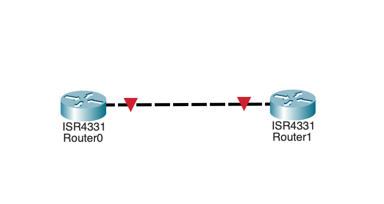
- ルーターを2つ作成し、接続します
ルーター1の設定
下記の設定を行います
| 設定 | 内容 |
|---|---|
| hostname | router1 |
| interface | GigabitEthernet 0/0/0 |
| → ip | 192.168.0.1 |
| → サブネットマスク | 255.255.255.0 |
-
router0のCLIを立ち上げます
-
enable > configure terminalでモードを変えます
Router> Router>enable Router#configure terminal Enter configuration commands, one per line. End with CNTL/Z. -
ホスト名を変更します
Router(config)#hostname router1 -
事前にインターフェイスを確認します
router1(config)#do show ip interface brief Interface IP-Address OK? Method Status Protocol GigabitEthernet0/0/0 unassigned YES unset administratively down down GigabitEthernet0/0/1 unassigned YES unset administratively down down GigabitEthernet0/0/2 unassigned YES unset administratively down down Vlan1 unassigned YES unset administratively down down -
インターフェイスを変更します
router1(config)#interface GigabitEthernet 0/0/0 router1(config-if)#ip address 192.168.0.1 255.255.255.0 router1(config-if)#no shutdown router1(config-if)# -
変更されたか確認します
router1(config-if)#do show ip interface brief
Interface              IP-Address      OK? Method Status                Protocol
GigabitEthernet0/0/0   192.168.0.1     YES manual up                    down
GigabitEthernet0/0/1   unassigned      YES unset  administratively down down
GigabitEthernet0/0/2   unassigned      YES unset  administratively down down
Vlan1                  unassigned      YES unset  administratively down down
router1(config-if)#exit
router1(config)#

router1(config)#do show running-config | section interface
interface GigabitEthernet0/0/0
 ip address 192.168.0.1 255.255.255.0
 duplex auto
 speed auto
interface GigabitEthernet0/0/1
ルーター2の設定
| 設定 | 内容 |
|---|---|
| hostname | router2 |
| interface | GigabitEthernet 0/0/0 |
| → ip | 192.168.0.2 |
| → サブネットマスク | 255.255.255.0 |
- CLIで変更します
Router>enable
Router#conf
Router#configure termina
Router#configure terminal
Enter configuration commands, one per line.  End with CNTL/Z.
Router(config)#hostname router2
router2(config)#do show ip interface brief
Interface              IP-Address      OK? Method Status                Protocol
GigabitEthernet0/0/0   unassigned      YES unset  administratively down down
GigabitEthernet0/0/1   unassigned      YES unset  administratively down down
GigabitEthernet0/0/2   unassigned      YES unset  administratively down down
Vlan1                  unassigned      YES unset  administratively down down
router2(config)#interface GigabitEthernet0/0/1
router2(config-if)#ip address 192.168.0.2 255.255.255.0
router2(config-if)#no shutdown

router2(config-if)#
%LINK-5-CHANGED: Interface GigabitEthernet0/0/1, changed state to up

router2(config-if)#
router2(config-if)#exit
router2(config)#do show ip interface brief
Interface              IP-Address      OK? Method Status                Protocol
GigabitEthernet0/0/0   unassigned      YES unset  administratively down down
GigabitEthernet0/0/1   192.168.0.2     YES manual up                    down
GigabitEthernet0/0/2   unassigned      YES unset  administratively down down
Vlan1                  unassigned      YES unset  administratively down down
router2(config)#do show running-config | section interface
interface GigabitEthernet0/0/0
 no ip address
 duplex auto
 speed auto
 shutdown
interface GigabitEthernet0/0/1
 ip address 192.168.0.2 255.255.255.0
 duplex auto
 speed auto
interface GigabitEthernet0/0/2
 no ip address
 duplex auto
 speed auto
 shutdown
interface Vlan1
 no ip address
 shutdown
router2(config)#
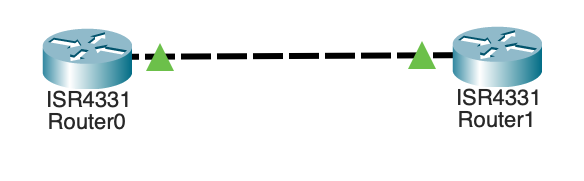
物理線のつなぎ直し
- 上記のインターフェイスに合わせて線をつなぎ直します。緑に変わりました
ステータスの確認と疎通
ルーター1
-
StatusとProtocolが両方 up になりました
router1#show ip interface brief Interface IP-Address OK? Method Status Protocol GigabitEthernet0/0/0 192.168.0.1 YES manual up up GigabitEthernet0/0/1 unassigned YES unset administratively down down GigabitEthernet0/0/2 unassigned YES unset administratively down down Vlan1 unassigned YES unset administratively down down router1# -
pingを打ちます。繋がりました
router1>ping 192.168.0.2

Type escape sequence to abort.
Sending 5, 100-byte ICMP Echos to 192.168.0.2, timeout is 2 seconds:
!!!!!
Success rate is 100 percent (5/5), round-trip min/avg/max = 0/0/0 ms

router1>
ルーター2
-
StatusとProtocolが両方 up になりました
router2>show ip interface brief Interface IP-Address OK? Method Status Protocol GigabitEthernet0/0/0 unassigned YES unset administratively down down GigabitEthernet0/0/1 192.168.0.2 YES manual up up GigabitEthernet0/0/2 unassigned YES unset administratively down down Vlan1 unassigned YES unset administratively down down router2> -
pingを打ちます。繋がりました
router2#ping 192.168.0.1

Type escape sequence to abort.
Sending 5, 100-byte ICMP Echos to 192.168.0.1, timeout is 2 seconds:
!!!!!
Success rate is 100 percent (5/5), round-trip min/avg/max = 0/0/0 ms

router2#
ルーティングテーブルの確認
別のNWと通信を試します。
下記の構成で設定します。
| 分類 | 項目 | 内容 |
|---|---|---|
| Router0 | hostname | R0 |
| GigabitEthernet0/0/0 | 192.168.1.1/24 | |
| GigabitEthernet0/0/1 | 192.168.2.1/24 | |
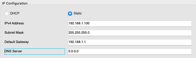
| PC0 | IPv4 | 192.168.1.100/24 |
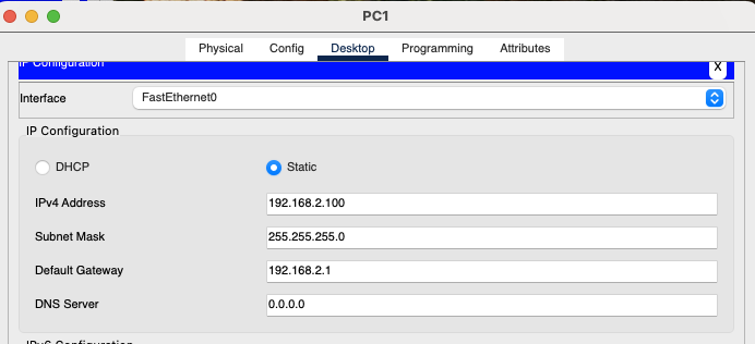
| PC1 | IPv4 | 192.168.2.100/24 |
Router0の設定
-
hostnameを設定します
Router#configure terminal Enter configuration commands, one per line. End with CNTL/Z. Router(config)#hostname R0 -
事前にinterfaceを確認します
R0(config)#do show ip interface GigabitEthernet0/0/0 is administratively down, line protocol is down (disabled) Internet protocol processing disabled GigabitEthernet0/0/1 is administratively down, line protocol is down (disabled) Internet protocol processing disabled GigabitEthernet0/0/2 is administratively down, line protocol is down (disabled) Internet protocol processing disabled Vlan1 is administratively down, line protocol is down Internet protocol processing disabled R0(config)#do show ip interface brief Interface IP-Address OK? Method Status Protocol GigabitEthernet0/0/0 unassigned YES unset administratively down down GigabitEthernet0/0/1 unassigned YES unset administratively down down GigabitEthernet0/0/2 unassigned YES unset administratively down down Vlan1 unassigned YES unset administratively down down R0(config)# -
1つ目のインターフェイスを設定します
R0(config)#interface GigabitEthernet0/0/0 R0(config-if)#ip address 192.168.1.1 255.255.255.0 R0(config-if)#no shutdown R0(config-if)# %LINK-5-CHANGED: Interface GigabitEthernet0/0/0, changed state to up %LINEPROTO-5-UPDOWN: Line protocol on Interface GigabitEthernet0/0/0, changed state to up R0(config-if)#exit ``` -
2つ目のインターフェイスを設定します
R0(config)#interface GigabitEthernet0/0/1 R0(config-if)#ip address 192.168.2.1 255.255.255.0 R0(config-if)#no shutdown R0(config-if)# %LINK-5-CHANGED: Interface GigabitEthernet0/0/1, changed state to up %LINEPROTO-5-UPDOWN: Line protocol on Interface GigabitEthernet0/0/1, changed state to up R0(config-if)#exit R0(config)# -
設定後の確認します。IPアドレスが設定され、upになりました
R0#show ip interface brief
Interface              IP-Address      OK? Method Status                Protocol
GigabitEthernet0/0/0   192.168.1.1     YES manual up                    up
GigabitEthernet0/0/1   192.168.2.1     YES manual up                    up
GigabitEthernet0/0/2   unassigned      YES unset  administratively down down
Vlan1                  unassigned      YES unset  administratively down down
R0#
PC0の設定
- PCをクリックし、Configタブをクリックします
- IPv4 Address、Subnet Mask、Default Gatewayを設定します
PC1の設定
- PCをクリックし、Desktopタブをクリックします
- IPv4 Address、Subnet Mask、Default Gatewayを設定します
ルートテーブルの確認
-
show ip routeで確認しますR0#show ip route Codes: L - local, C - connected, S - static, R - RIP, M - mobile, B - BGP D - EIGRP, EX - EIGRP external, O - OSPF, IA - OSPF inter area N1 - OSPF NSSA external type 1, N2 - OSPF NSSA external type 2 E1 - OSPF external type 1, E2 - OSPF external type 2, E - EGP i - IS-IS, L1 - IS-IS level-1, L2 - IS-IS level-2, ia - IS-IS inter area * - candidate default, U - per-user static route, o - ODR P - periodic downloaded static route Gateway of last resort is not set 192.168.1.0/24 is variably subnetted, 2 subnets, 2 masks C 192.168.1.0/24 is directly connected, GigabitEthernet0/0/0 L 192.168.1.1/32 is directly connected, GigabitEthernet0/0/0 192.168.2.0/24 is variably subnetted, 2 subnets, 2 masks C 192.168.2.0/24 is directly connected, GigabitEthernet0/0/1 L 192.168.2.1/32 is directly connected, GigabitEthernet0/0/1 R0# - 上記は、全部で4行表示されました
- C:ルーターに直接接続されているルート
- L:自身のインターフェイスルート
- 192.168.1.0/24、192.168.2.0/24:宛先のNWとサブネットマスク
- is directly connected:ネクストホップ
- GigabitEthernet0/0/0、GigabitEthernet0/0/1:パケットの送出先のインターフェイス名
疎通(PC0→PC1)
-
pingを実行します。成功しましたC:\>ping 192.168.2.100 Pinging 192.168.2.100 with 32 bytes of data: Reply from 192.168.2.100: bytes=32 time=4ms TTL=127 Reply from 192.168.2.100: bytes=32 time=4ms TTL=127 Reply from 192.168.2.100: bytes=32 time=4ms TTL=127 Reply from 192.168.2.100: bytes=32 time=4ms TTL=127 Ping statistics for 192.168.2.100: Packets: Sent = 4, Received = 4, Lost = 0 (0% loss), Approximate round trip times in milli-seconds: Minimum = 4ms, Maximum = 4ms, Average = 4ms C:\>
疎通(PC1→PC0)
-
pingを実行します。成功しましたC:\>ping 192.168.1.100 Pinging 192.168.1.100 with 32 bytes of data: Reply from 192.168.1.100: bytes=32 time<1ms TTL=127 Reply from 192.168.1.100: bytes=32 time<1ms TTL=127 Reply from 192.168.1.100: bytes=32 time=1ms TTL=127 Reply from 192.168.1.100: bytes=32 time<1ms TTL=127 Ping statistics for 192.168.1.100: Packets: Sent = 4, Received = 4, Lost = 0 (0% loss), Approximate round trip times in milli-seconds: Minimum = 0ms, Maximum = 1ms, Average = 0ms C:\>
考察
今回ルータを用意して、簡単に動作を確認してみました。次回はルートテーブルを書き変えてみます。
参考