はじめに
ネットの先人たちの情報を、あれもこれも使わせて頂き、まだまだ初心者ですが、色々と遊ばせて頂いています。既出の情報ばかりかとは思いますが、自分のメモとして投稿させて頂きます。ご容赦くださいませ。
構成
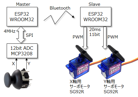
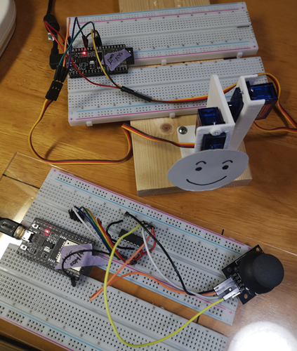
ESP32同士をBluetoothで接続し、片方のESP32に接続されたMCP3208 (ADコンバーター)から読んだXYジョイスティックの値を、もう一方のESP32に飛ばして、XY軸でサーボモーターを動かしてみました。Bluetoothの接続は、MACアドレスを直接指定する形で実現しましたので、このままでは、汎用性がありませんが、実験としては上手くいきましたのでメモとして残しておきます。ジョイスティックを動かすと、スマイリー君がうなづいたり、顔を回転させるだけですが・・・・
マスタ側
アナログジョイスティックの読み取り
別の投稿にあげたやり方と同じですが、12bit ADCのMCP3208(安価で12bit x 8CHあって便利。差動が擬似なのが残念)と、ESP32を 4MHzのSPI(HSPI)で接続して、約20msec毎に値を読取ります。20msecにしたのは、サーボモータのPWM周期が20msecなので、それよりも高速で送っても意味が無いと思ったからです。そもそも、Bluetoothがどのくらいの周期でパケットを送れるのかよく知らない(調べればいいのですが・・・)
SPIライブラリは一般的な SPI.hを使い、一般的なピン配列で Mode 0 をつかって 4MMzのクロックで通信しました。
MCP3208が 5bitコマンド+1bitダミー+1bit NULL + 12bitデータという信号フォーマットなのですが、SPI.Hの8bit単位のSPI通信を使うために、先頭に5bitダミーのゼロを送り、5bit+ 19bitで 24ビット(3byte)にして通信しました。
uint16_t adc_read(uint8_t channel) {
  digitalWrite(SPI1_SS, LOW);
  SPI1.transfer(0x06 | channel>>2);//bit7-3:dummy, bit2:start, bit1:single,bit0:D2
  uint8_t dh = SPI1.transfer((channel & 0x03) << 6);//D1,D0,X,Null,B11-B8
  uint8_t dl = SPI1.transfer(0x00);//B7-B0
  digitalWrite(SPI1_SS, HIGH);
  return ((dh & 0xF) << 8 | dl); //get 12bits data
}
ジョイスティックで読んだ X, Yの二つの数値 (0~4095)を、コンマ区切りの文字列でスレーブ側に送ります。また後述しますが、スレーブ側でのバッファ読取りで、SerialBT.readStringUntil('\0')を使い、文字列の最後に'\0' がある事を前提としているため、XとYの値を、以下のように連結して送るようにしました。
void loop() {
  uint16_t xval = adc_read(0); //Channel-0
  uint16_t yval = adc_read(1); //Channel-1
  String str = String(xval) + ',' +String(yval) + '\0';
  Serial.println(str);
  SerialBT.print(str);
  delay(20);
}
Bluetooth接続
Bluetoothについて勉強不足なので、ネットの先人たちの情報を大変参考にさせて頂きました。基本は、ESP32をボードマネジャーで Arduino IDEにインストールした時に入ってきたサンプルコードをほぼ使った形です。
スレーブ側のMACアドレスを調べる
(すみません。ネットの先人のサイトから頂きましたが、リンクが見つかりません)
このコードをスレーブ側のESP32に書き込み、実行すると、MACアドレスを取得する事ができるので、メモしておきます。(6バイトのデータです)
void setup(void) {
  Serial.begin(115200);
  Serial.println("-----------------");
  uint8_t macBT[6];
  esp_read_mac(macBT, ESP_MAC_BT);
  Serial.printf("%02X:%02X:%02X:%02X:%02X:%02X\r\n", macBT[0], macBT[1], macBT[2], macBT[3], macBT[4], macBT[5]);
}

void loop() {
  delay(1000);
}
MACアドレスを指定しなくても、名前で検索して接続するのが正しいやり方だと思いますが、接続に時間がかかるという話もあったので、まず実験としては、MACアドレス直接指定で進めました。
マスター側のコードでスレーブ側のアドレスを直接指定
SerialToSerialBTMのコードをほぼ、そのまま利用させて頂きました。(スレーブ側は、SerialToSerialBTを参考にしました)

このコードを基に、MACアドレスを接続相手のスレーブの値に合わせて修正し、また、nameを使わないで MAC Addressを使うようにコメントアウトやアンコメントした結果が以下のコードです。
BluetoothSerial SerialBT;
String MACadd = "**:**:**:**:**:**";
uint8_t address[6] = {0x**, 0x**, 0x**, 0x**, 0x**, 0x**};
bool connected;
void init_BT() { // Setup Bluetooth connection
  SerialBT.begin("ESP32_MASTER", true);
  Serial.println("Master Device:");
  connected = SerialBT.connect(address);
  if (connected) {
    Serial.println("Connected Succesfully!");
  } else {
    while (!SerialBT.connected(10000)) {
      Serial.println("Failed to connect. Make sure remote device is available and in range, then restart app.");
    }
  }
  if (SerialBT.disconnect()) {
    Serial.println("Disconnected Succesfully!");
  }
  SerialBT.connect();//reconnect
}
マスター側のコード全容
# include <SPI.h>
# include "BluetoothSerial.h"

BluetoothSerial SerialBT;
String MACadd = "**:**:**:**:**:**";
uint8_t address[6] = {0x**, 0x**, 0x**, 0x**, 0x**, 0x**};
bool connected;
void init_BT() { // Setup Bluetooth connection
  SerialBT.begin("ESP32_MASTER", true);
  Serial.println("Master Device:");
  connected = SerialBT.connect(address);
  if (connected) {
    Serial.println("Connected Succesfully!");
  } else {
    while (!SerialBT.connected(10000)) {
      Serial.println("Failed to connect. Make sure remote device is available and in range, then restart app.");
    }
  }
  if (SerialBT.disconnect()) {
    Serial.println("Disconnected Succesfully!");
  }
  SerialBT.connect();//reconnect
}

# define SPI1_CLK  32
# define SPI1_MISO 33
# define SPI1_MOSI 25
# define SPI1_SS   26
# define SPI_CLK 4000000
SPIClass SPI1(HSPI);
SPISettings spiSettings = SPISettings(SPI_CLK, SPI_MSBFIRST, SPI_MODE0);//0,0
void init_SPI() { // Setup SPI connection
  SPI1.begin(SPI1_CLK, SPI1_MISO, SPI1_MOSI, SPI1_SS);
  pinMode(SPI1_SS, OUTPUT);
  pinMode(SPI1_CLK, OUTPUT);
  pinMode(SPI1_MISO, INPUT);
  pinMode(SPI1_MOSI, OUTPUT);
  digitalWrite(SPI1_SS, HIGH) ;
  SPI1.beginTransaction(spiSettings);
}
void setup() {
  Serial.begin(115200);
  init_BT();
  init_SPI();
}
void loop() {
  uint16_t xval = adc_read(0); //Channel-0
  uint16_t yval = adc_read(1); //Channel-1
  String str = String(xval) + ',' +String(yval) + '\0';
  Serial.println(str);
  SerialBT.print(str);
  delay(20);
}
uint16_t adc_read(uint8_t channel) {
  digitalWrite(SPI1_SS, LOW);
  SPI1.transfer(0x06 | channel>>2);//bit7-3:dummy, bit2:start, bit1:single,bit0:D2
  uint8_t dh = SPI1.transfer((channel & 0x03) << 6);//D1,D0,X,Null,B11-B8
  uint8_t dl = SPI1.transfer(0x00);//B7-B0
  digitalWrite(SPI1_SS, HIGH);
  return ((dh & 0xF) << 8 | dl); //get 12bits data
}
スレーブ側
スレーブ側は、サンプルコードを参考にして、setup()の中で初期化し、loop()の中では、readStringUntil()をつかって、マスターから送られてくる文字列の終端文字まで読み、文字列として処理に使います。一文字ずつ読むよりも効率が良いのと、今回のように、マスターも自分で作る場合には、送られてくる文字列の終端を、自分で決めることが出来るのでこの方法が良いと思われます。今回は、'\0'のNULL文字をマスターから送る文字列の終端文字に指定しています。
  if (SerialBT.available()) {
    String buf = SerialBT.readStringUntil('\0');
あとは、読み取ったバッファから必要なデータを取り出して、サーボモータを制御すればよい事になります。残念ながら、Arduinoの開発環境でコンマで文字列を区切る関数 (split()みたいな関数)が無いみたいなので、コンマの位置を探して、部分文字列に分割してから、整数化し、最後に、サーボモーターに送る数字範囲へのマッピングを行ってから、PWM出力しています。
  if (SerialBT.available()) {
    String buf = SerialBT.readStringUntil('\0');
    Serial.println(buf);
    int pos = buf.indexOf(','); //最初のコンマを探し、その文字位置を得る
    int xval = buf.substring(0, pos).toInt(); //頭から、最初のコンマの1文字前まで得てから整数化
    int yval = buf.substring(pos + 1).toInt(); //コンマの次から最後まで得てから整数化
    int x = (int)map(xval, 0, 4095, 60, 230); // <- 0~4095の値を 50~230へマッピング。便利!
    int y = (int)map(yval, 0, 4095, 50, 230);
    ledcWrite(1, x); //PWM出力してサーボを動かす
    ledcWrite(2, y);
  }
ちなみに、ESP32のPWM制御には、今回 ledcライブラリを使っています。GPIO25と GPIO26に、それぞれ X軸用 (Motor1)と、Y軸(Motor2)のPWM出力を割り当て、ledcライブラリの中でつかうために、ledcAttachPinでESP32の内部PWMチャンネルを連結させています。
# include "esp32-hal-ledc.h"

# define Motor1 25
# define Motor2 26

void setup() {
  Serial.begin(115200);
  ledcSetup(1, 50, 11);//CH:1,Freq:50Hz,Res:11bit
  ledcAttachPin(Motor1, 1);
  ledcAttachPin(Motor2, 2);
スレーブ側のコード全容
# include "esp32-hal-ledc.h"
# include "BluetoothSerial.h"
BluetoothSerial SerialBT;

//COM17 in my environment
# define Motor1 25
# define Motor2 26

void setup() {
  Serial.begin(115200);
  ledcSetup(1, 50, 11);//CH:1,Freq:50Hz,Res:11bit
  ledcAttachPin(Motor1, 1);
  ledcAttachPin(Motor2, 2);
  SerialBT.begin("ESP32_SLAVE"); //Bluetooth device name
  Serial.println("Slave Device:");
}

int xmin = 60; //for 0.586ms
int xmax = 230; //for 2.246ms
void loop() {
  if (SerialBT.available()) {
    String buf = SerialBT.readStringUntil('\0');
    Serial.println(buf);
    int pos = buf.indexOf(',');
    int xval = buf.substring(0, pos).toInt();
    int yval = buf.substring(pos + 1).toInt();
    int x = (int)map(xval, 0, 4095, 60, 230);
    int y = (int)map(yval, 0, 4095, 50, 230);
    ledcWrite(1, x);
    ledcWrite(2, y);
  }
  delay(1);
}
追記
ESP32での実験をする前に、ESP8266でWiFiをつかって、Node-REDでMQTTメッセージを使い、同じような事を試してみたのですが、あちこちでバッファ処理が入り、いくつかの数値が集められたパケットがスレーブ側に届くため、動きが全くスムーズで無く諦めました。 Bluetoothを使ったのは今回が初めてでしたが、ESP32のBluetoothが簡単につながる事が確認でき、レイテンシーも全く問題なく、非常にすっきりとスマイリー君が動きました。本当に昨今の開発環境の整備具合や、ネット情報の豊富さには驚くばかりです。
今回作ったプロトを、3Dプリンタで作ったちょっとした箱に入れて、今度、孫が遊びに来た時に、ちょっと試してみようかな・・・と思ってます。喜んでくれないかな・・・・。