これは何?
独自の図形を描画する際にPathを使えばいいというのは分かっていたが、実際どういうAPIが存在しているのか把握してなかったので、Pathのドキュメントを上から下まで読んで自分なりにまとめたものです。
Pathとは
2Dの形状の輪郭(アウトライン)を示すもの。
Path自体は塗りつぶされた図形のことを指さず、その形の輪郭・外枠を示す。
Pathの基本
Pathは親Viewの左上を原点とし、右に行くほどXが+、下に行くほどYが+になる。
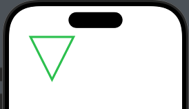
詳細は後述するが、以下が基本的な構造で、Pathのクロージャ内でmove(to:)で描画開始位置に移動し、addLine(to:)で線を引いてcolosePath()で閉じるといった感じ。
struct ContentView: View {
    var body: some View {
        Path { path in
            path.move(to: CGPoint(x: 50, y: 10))
            path.addLine(to: CGPoint(x: 150, y: 10))
            path.addLine(to: CGPoint(x: 100, y: 110))
            path.closeSubpath()
        }
        .stroke(.green, lineWidth: 5)
    }
}
空のPathを生成してからaddしていくことも可能。
struct ContentView: View {
    var triangle: Path {
        var path = Path()
        path.move(to: CGPoint(x: 50, y: 10))
        path.addLine(to: CGPoint(x: 150, y: 10))
        path.addLine(to: CGPoint(x: 100, y: 110))
        path.closeSubpath()
        return path
    }

    var body: some View {
        triangle
            .stroke(.green, lineWidth: 5)
    }
}
実行結果は前のと同じ。
Shapeプロトコルに準拠した定義
Shapeに準拠させることで動的に図形を調整しやすくなるので、実際はこのように使うことが多いかも。
struct CustomShape: Shape {
    func path(in rect: CGRect) -> Path {
        Path { path in
            path.move(to: CGPoint(x: rect.minX, y: rect.minY))
            path.addLine(to: CGPoint(x: rect.maxX, y: rect.minY))
            path.addLine(to: CGPoint(x: rect.midX, y: rect.maxY))
            path.closeSubpath()
        }
    }
}

struct ContentView: View {
    var body: some View {
        VStack {
            CustomShape()
                .stroke(.green, lineWidth: 5)
                .frame(width: 100, height: 100)
            CustomShape()
                .stroke(.green, lineWidth: 5)
                .frame(width: 200, height: 300)
        }
    }
}
基本的な描画操作
Pathの基本操作をまとめる
move(to:) と closeSubpath()
Pathにはsubpathという概念が存在する。
これは1つのPathオブジェクトで複数の図形を描画するために存在し、描画する図形数に応じてPathに複数のsubpathが生成される。
move(to:)は描画開始位置へ移動すると共に新しいsubpathを作成する。
closeSubpath()でsubpathを閉じることができ、更にsubpathの開始位置へ自動的に線を引くため、冒頭の三角を描画するコードでは2回のaddLine(to:)で済んでいる。
        Path { path in
            // 描画開始位置へ移動すると共に新しいsubpathを作成
            path.move(to: CGPoint(x: 50, y: 10))
            // 線を描画
            path.addLine(to: CGPoint(x: 150, y: 10))
            path.addLine(to: CGPoint(x: 100, y: 110))
            // subpathを閉じる
            // 開始位置へ自動的に線を引く
            path.closeSubpath()
        }
addRect(_:transform:)のような形状がそれだけで完結するものに関してはmove(to:)やcloseSubpath()は不要
線の描画
addLine(to:)
1本の線を描画する
        Path { path in
             path.move(to: CGPoint(x: 10, y: 0))
             path.addLine(to: CGPoint(x: 100, y: 0))
             path.addLine(to: CGPoint(x: 100, y: 100))
             path.addLine(to: CGPoint(x: 10, y: 100))
             path.closeSubpath()
         }
         .stroke(.green, lineWidth: 5)
addLines(_:)
複数の線を描画する
        Path { path in
            path.move(to: CGPoint(x: 10, y: 0))
            path.addLines([
                CGPoint(x: 100, y: 0),
                CGPoint(x: 100, y: 100),
                CGPoint(x: 10, y: 100),
                CGPoint(x: 10, y: 0)
            ])
            path.closeSubpath()
        }
        .stroke(.green, lineWidth: 5)
上記コードでは先ほどと異なり最後に始点であるCGpoint(x: 10, y: 10)を指定している。
addLines(_:)ではaddLine(to:)と異なり、最後に始点まで指定しないと思い通りに描画されないので注意。
        Path { path in
            path.move(to: CGPoint(x: 10, y: 0))
            path.addLines([
                CGPoint(x: 100, y: 0),
                CGPoint(x: 100, y: 100),
                CGPoint(x: 10, y: 100),
                // 始点まで指定しないと三角になる
                // CGPoint(x: 10, y: 0)
            ])
            path.closeSubpath()
        }
短形の描画
addRect(_:transform:)
1つの短形を描画する。
        Path { path in
            path.addRect(CGRect(x: 10, y: 10, width: 100, height: 200))
        }
        .stroke(.green, lineWidth: 5)
transform引数ではCGAffineTransformで回転・拡大・並行移動・傾斜・反転などができる。デフォルト引数で.identity(単位行列)が指定されている。
addRects(_:transform:)
複数の短形を描画する
        Path { path in
            path.addRects([
                CGRect(x: 10, y: 10, width: 100, height: 200),
                CGRect(x: 150, y: 10, width: 100, height: 200),
            ])
        }
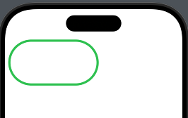
init(roundedRect:cornerRadius:style:)
角丸の短形を描画する
        Path(
            roundedRect: CGRect(x: 10, y: 10, width: 200, height: 100),
            cornerRadius: 10,
            style: .circular
        )
        .stroke(.green, lineWidth: 5)
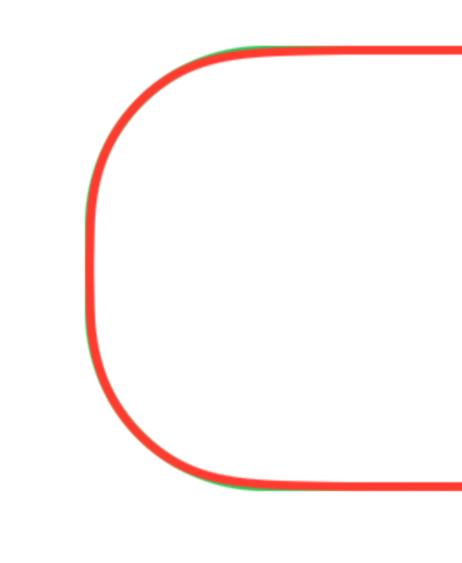
styleは角丸の形状を示す。
- circular
- 直線からカーブにかけてシャープになる
- continuous
- 直線からカーブにかけて滑らか。circularより滑らか
↓緑の.circularの角丸と赤の.continuousの角丸をZStackで重ねたもの。circularの方が直線からカーブにかけて.continuousに比べて若干外に出てるが、ぱっと見違いは無さそう。
init(roundedRect:cornerSize:style:)
角の丸みが均一ではない角丸短形を描画できる
1つ前のcornerRadiusでは角の丸みの半径をCGFloatで指定していたので丸みが均一になっていた。このcornerSizeでは角の丸みをCGSizeで指定できるので、楕円形に丸めることが可能になる。
        Path(
            roundedRect: CGRect(x: 10, y: 10, width: 200, height: 100),
            cornerSize: CGSize(width: 20, height: 50),
            style: .circular
        )
        .stroke(.green, lineWidth: 5)
例えばwidthとheightを50, 50にするとcornerRadiusと同じように丸みが均一化される。
init(roundedRect:cornerRadii:style:)
4つの角ごとに異なる丸みを指定可能な短形を描画する。
        Path(
            roundedRect: CGRect(x: 10, y: 10, width: 200, height: 100),
            cornerRadii: RectangleCornerRadii(
                topLeading: 10,
                bottomLeading: 20,
                bottomTrailing: 30,
                topTrailing: 40
            ),
            style: .continuous
        )
        .stroke(.green, lineWidth: 5)
addRoundedRect(in:cornerSize:style:transform:)
角丸短形をpathに追加する
        Path { path in
            path.addRoundedRect(
                in: CGRect(x: 10, y: 10, width: 100, height: 200),
                cornerSize: CGSize(width: 30, height: 30)
            )
        }
        .stroke(.green, lineWidth: 5)
addRoundedRect(in:cornerRadii:style:transform:)
角の丸みが均一ではない角丸短形をpathに追加する
        Path { path in
            path.addRoundedRect(in: CGRect(x: 10, y: 10, width: 100, height: 200),
                                cornerRadii: RectangleCornerRadii(
                                    topLeading: 10,
                                    bottomLeading: 20,
                                    bottomTrailing: 30,
                                    topTrailing: 40
                                ))
        }
        .stroke(.green, lineWidth: 5)
楕円の描画
init(ellipseIn:)
楕円のPathを描画
CGRectが正方形の場合は均等な円を描画できる
        VStack {
            Path(ellipseIn: CGRect(x: 10, y: 10, width: 200, height: 100))
                .stroke(.green, lineWidth: 5)
            Path(ellipseIn: CGRect(x: 10, y: 10, width: 200, height: 200))
                .stroke(.green, lineWidth: 5)
        }
addEllipse(in:transform:)
Pathに楕円を追加する
        Path { path in
            path.addEllipse(in: CGRect(x: 50, y: 50, width: 200, height: 100))
            path.addEllipse(in: CGRect(x: 50, y: 200, width: 200, height: 200))
        }
        .stroke(.green, lineWidth: 5)
弧の描画
addArc(center:radius:startAngle:endAngle:clockwise:transform:)
弧を描画する
        Path { path in
             path.addArc(
                 center: CGPoint(x: 100, y: 100), // 中心
                 radius: 50, // 半径
                 startAngle: .degrees(40), // 開始角度。時計の4時あたり
                 endAngle: .degrees(180), // 終了角度。時計の9時あたり
                 clockwise: true // 時計回りに描画
             )
         }
         .stroke(Color.green, lineWidth: 5)
clockwiseをfalseにすると反時計回りに描画される
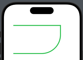
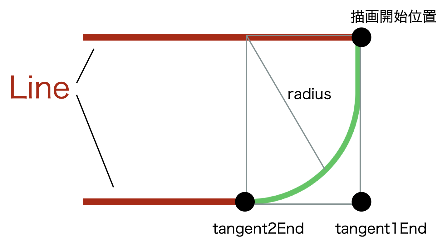
addArc(tangent1End:tangent2End:radius:transform:)
特定のポイントに向かって弧を描く
        Path { path in
            path.move(to: CGPoint(x: 50, y: 50))
            path.addLine(to: CGPoint(x: 300, y: 50))
            path.addArc(
                tangent1End: CGPoint(x: 300, y: 200),
                tangent2End: CGPoint(x: 200, y: 200),
                radius: 100
            )
            path.addLine(to: CGPoint(x: 50, y: 200))
        }
        .stroke(.green, lineWidth: 5)
描画開始位置からtangent2Endに向かって弧を描画するが、tangent1Endに向かってカーブを描く。
addRelativeArc(center:radius:startAngle:delta:transform:)
相対的な弧を描画する。
addArc(center:radius:startAngle:endAngle:clockwise:transform:)では開始角度と終了角度を明示的に示したが、addRelativeArcでは開始角度とそこからどの程度描画するかを指定する。
以下の例では40度(時計の4時あたり)から180度分時計回りに描画している。
        Path { path in
            path.addRelativeArc(
                center: CGPoint(x: 100, y: 100),
                radius: 50,
                startAngle: .degrees(40),
                delta: .degrees(180)
            )
        }
        .stroke(.green, lineWidth: 5)
ベジェ曲線の描画
addQuadCurve(to:control:)
2次ベジェ曲線(1つの制御点を持つ曲線)を描画
        Path { path in
            path.move(to: CGPoint(x: 0, y: 100)) // 始点
            path.addQuadCurve(
                to: CGPoint(x: 300, y: 100), // 終点
                control: CGPoint(x: 150, y: 0) // 制御点
            )
        }
        .stroke(.green, lineWidth: 5)
制御点が中央上に来るように配置している。
イメージ的には以下のような感じ。
    var linePath: Path {
        Path { path in
            path.move(to: CGPoint(x: 0, y: 100))
            path.addLine(to: CGPoint(x: 150, y: 0))
            path.addLine(to: CGPoint(x: 300, y: 100))
        }
    }

    var controlPath: Path {
        Path { path in
            path.addArc(center: CGPoint(x: 150, y: 0), radius: 5, startAngle: .zero, endAngle: .degrees(360), clockwise: true)
        }
    }

    var body: some View {
        ZStack {
            linePath
                .stroke(.red, lineWidth: 5)
            controlPath
                .stroke(.blue, lineWidth: 5)
            // ベジェ曲線
            Path { path in
                path.move(to: CGPoint(x: 0, y: 100)) // 始点
                path.addQuadCurve(
                    to: CGPoint(x: 300, y: 100), // 終点
                    control: CGPoint(x: 150, y: 0) // 制御点
                )
            }
            .stroke(.green, lineWidth: 5)
        }
    }
addCurve(to:control1:control2:)
3次ベジェ曲線(2つの制御点を持つ曲線)を描画
        Path { path in
            path.move(to: CGPoint(x: 0, y: 100)) // 始点
            path.addCurve(
                to: CGPoint(x: 300, y: 100), // 終点
                control1: CGPoint(x: 150, y: 0), // 1つ目の制御点
                control2: CGPoint(x: 150, y: 200) // 2つ目の制御点
            )
        }
        .stroke(.green, lineWidth: 5)
2つの制御点は中央の上下に来るように配置している。
イメージ的には以下のような感じ。
    var linePath: Path {
        Path { path in
            path.move(to: CGPoint(x: 0, y: 100))
            path.addLine(to: CGPoint(x: 150, y: 0))
            path.addLine(to: CGPoint(x: 150, y: 200))
            path.addLine(to: CGPoint(x: 300, y: 100))
        }
    }

    var controlPath: Path {
        Path { path in
            path.addArc(center: CGPoint(x: 150, y: 0), radius: 5, startAngle: .zero, endAngle: .degrees(360), clockwise: true)
            path.addArc(center: CGPoint(x: 150, y: 200), radius: 5, startAngle: .zero, endAngle: .degrees(360), clockwise: true)
        }
    }

    var body: some View {
        ZStack {
            linePath
                .stroke(.red, lineWidth: 5)
            controlPath
                .stroke(.blue, lineWidth: 5)
            // ベジェ曲線
            Path { path in
                path.move(to: CGPoint(x: 0, y: 100)) // 始点
                path.addCurve(
                    to: CGPoint(x: 300, y: 100), // 終点
                    control1: CGPoint(x: 150, y: 0), // 1つ目の制御点
                    control2: CGPoint(x: 150, y: 200) // 2つ目の制御点
                )
            }
            .stroke(.green, lineWidth: 5)
        }
    }
move(to:)とcloseSubpath()の重要性
先述した通り、move(to:)で描画開始位置へ移動してsubpathを作成し、closeSubpath()でsubpathを閉じることができる。
例えば以下のようにPath内で2つの図形を描画するとする。
        Path { path in
            // 1つ目の図形
            path.move(to: CGPoint(x: 50, y: 50))
            path.addLine(to: CGPoint(x: 150, y: 50))
            path.addLine(to: CGPoint(x: 150, y: 150))
            path.addLine(to: CGPoint(x: 50, y: 150))
            path.closeSubpath()

            // 2つ目の図形
            path.move(to: CGPoint(x: 200, y: 50))
            path.addLine(to: CGPoint(x: 300, y: 50))
            path.addLine(to: CGPoint(x: 300, y: 150))
            path.addLine(to: CGPoint(x: 200, y: 150))
            path.closeSubpath()
        }
        .stroke(.green, lineWidth: 5)
もし1つ目の図形でcloseSubpath()しない場合、始点までの線は描画されない。subpathが閉じられないままなので.fillなどで塗りつぶした際に正常に塗りつぶされない可能性がある。
今度は2つ目の図形でmove(to:)せずにaddLine(to:)など続けてしまうと、前のsubpathと同じ始点からsubpathが暗黙的に作成される。
        Path { path in
            // 1つ目の図形
            path.move(to: CGPoint(x: 50, y: 50))
            path.addLine(to: CGPoint(x: 150, y: 50))
            path.addLine(to: CGPoint(x: 150, y: 150))
            path.addLine(to: CGPoint(x: 50, y: 150))
            path.closeSubpath()

            // 2つ目の図形
            // path.move(to: CGPoint(x: 200, y: 50))
            path.addLine(to: CGPoint(x: 300, y: 50))
            path.addLine(to: CGPoint(x: 300, y: 150))
            path.addLine(to: CGPoint(x: 200, y: 150))
            path.closeSubpath()
        }
        .stroke(.green, lineWidth: 5)
1つ目の図形でmove(to:)しない場合、線が描画されない。これはmove(to:)により作成されていたsubpathが存在しないため。
        Path { path in
            // 1つ目の図形
            // path.move(to: CGPoint(x: 50, y: 50))
            path.addLine(to: CGPoint(x: 150, y: 50))
            path.addLine(to: CGPoint(x: 150, y: 150))
            path.addLine(to: CGPoint(x: 50, y: 150))
            path.closeSubpath()

            // 2つ目の図形
            path.move(to: CGPoint(x: 200, y: 50))
            path.addLine(to: CGPoint(x: 300, y: 50))
            path.addLine(to: CGPoint(x: 300, y: 150))
            path.addLine(to: CGPoint(x: 200, y: 150))
            path.closeSubpath()
        }
        .stroke(.green, lineWidth: 5)
addRects(_:transform:)などでmove(to:)をしなくていいのは、内部でsubpathの作成とcloseを両方して完結しているため。
Pathの始点と終点を指定する以下3つを使う場合は気をつけよう。
addLine(to:)addQuadCurve(to:control:)addCurve(to:control1:control2:)
Path.Element
PathのElementとして以下のcaseがある
- Path.Element.move(to:)
- Path.Element.line(to:)
- Path.Element.curve(to:control1:control2:)
- Path.Element.quadCurve(to:control:)
- Path.Element.closeSubpath
forEach(_:)
これらのPath.ElementをforEachで取り出すことができる。
なのでPath内の各要素を取り出して任意の処理を実行することが可能。
例えばmove(to:)した値に合わせて動的にaddLine(to:)の値を調整したりなどできそう。
    let path = Path { path in
        path.move(to: CGPoint(x: 50, y: 50))
        path.addLine(to: CGPoint(x: 150, y: 50))
        path.addLine(to: CGPoint(x: 150, y: 150))
        path.addQuadCurve(to: CGPoint(x: 50, y: 150), control: CGPoint(x: 100, y: 200))
        path.closeSubpath()
    }

    func printEachElement() {
        path.forEach { element in
            switch element {
            case .move(let point):
                print("Move to \(point)")
            case .line(let point):
                print("Line to \(point)")
            case .quadCurve(let point, let control):
                print("Quad curve to \(point), control: \(control)")
            case .curve(let point, let control1, let control2):
                print("Curve to \(point), control1: \(control1), control2: \(control2)")
            case .closeSubpath:
                print("Close subpath")
            }
        }
    }
Move to (50.0, 50.0)
Line to (150.0, 50.0)
Line to (150.0, 150.0)
Quad curve to (50.0, 150.0), control: (100.0, 200.0)
Close subpath
Pathの操作
Pathの追加
addPath(_:transform:)で現在のPathに別のPathを追加する。
1つのPathを複数回使用する場合や、複雑な図形を作る時にパーツごとでPathを生成したりなどで使えそう。
以下の例では楕円を1つ描画し、transformを用いて同じ楕円の位置をずらして表示している。
    var ellipsePath: Path {
        Path { path in
            path.addEllipse(in: CGRect(x: 50, y: 50, width: 200, height: 100))
        }
    }

    var body: some View {
        Path { path in
            path.addPath(ellipsePath)
            let transform = CGAffineTransform(translationX: 50, y: 50)
            path.addPath(ellipsePath, transform: transform)
        }
        .stroke(Color.green, lineWidth: 2)
    }
以下の例では楕円を1つ描画し、transformを用いて同じ楕円の位置をずらして表示している
共通領域の取得
intersection(_:eoFill:)で2つのPathの共通領域を取得する
例えばrectとellipseを同時に描画すると以下のようになるとする
    var rectPath = Path { path in
        path.addRect(CGRect(x: 50, y: 50, width: 100, height: 100))
    }

    var ellipsePath = Path { path in
        path.addEllipse(in: CGRect(x: 70, y: 70, width: 100, height: 100))
    }

    var body: some View {
        Path { path in
            path.addPath(rectPath)
            path.addPath(ellipsePath)
        }
        .stroke(.green, lineWidth: 5)
    }
これにintersection(_:eoFill:)を適用した場合
    var body: some View {
        HStack {
            rectPath
                .intersection(ellipsePath)
                .stroke(.green, lineWidth: 5)
            ellipsePath
                .intersection(rectPath)
                .stroke(.green, lineWidth: 5)
        }
    }
どちらのPathに対して行っても共通領域は同じなので結果も同じ。
非共通領域の取得
subtracting(_:eoFill:)で共通領域ではない部分を取得する。
    var body: some View {
        HStack {
            rectPath
                .subtracting(ellipsePath)
                .stroke(.green, lineWidth: 5)
            ellipsePath
                .subtracting(rectPath)
                .stroke(.green, lineWidth: 5)
        }
    }
共通領域の線を取得
lineIntersection(_:eoFill:)で共通領域の線のみを取得する
    var body: some View {
        HStack {
            rectPath
                .lineIntersection(ellipsePath)
                .stroke(.green, lineWidth: 5)
            ellipsePath
                .lineIntersection(rectPath)
                .stroke(.green, lineWidth: 5)
        }
    }
非共通領域の線を取得
lineSubtraction(_:eoFill:)で共通領域ではない線を取得する。
    var body: some View {
        HStack {
            rectPath
                .lineSubtraction(ellipsePath)
                .stroke(.green, lineWidth: 5)
            ellipsePath
                .lineSubtraction(rectPath)
                .stroke(.green, lineWidth: 5)
        }
    }
normalized(eoFill:)
自己交差しているpathを正規化し、自己交差がないPath(弱単純パス: weakly-simple path)にする。
例えば以下のようなpathは数字の8を描くように自身のlineで交差している。これが自己交差。この状態では正しく塗りつぶしや描画が行われない可能性がある。
    let path = Path { path in
        path.move(to: CGPoint(x: 50, y: 50))
        path.addLine(to: CGPoint(x: 150, y: 150))
        path.addLine(to: CGPoint(x: 50, y: 150))
        path.addLine(to: CGPoint(x: 150, y: 50))
    }

    var body: some View {
        path
            .stroke(.green, lineWidth: 5)
    }
そこでnormalized(eoFill:)を行うことで、自己交差しないpathに内部的に変更を加えてくれる。
    var body: some View {
        path
            .normalized()
            .stroke(.green, lineWidth: 5)
    }
見た目的にはcloseSubpath()された(一番上にlineが追加された)ようにしか見えないが、先述したpathの要素をforEachで出力してみると、交差されないようにpathが調整されているのがわかる。
		path.normalized().forEach { element in
        switch element {
        case .move(let point):
            print("Move to \(point)")
        case .line(let point):
            print("Line to \(point)")
				...
				}
		}
.normalized()前
Move to (50.0, 50.0)
Line to (150.0, 150.0)
Line to (50.0, 150.0)
Line to (150.0, 50.0)
.normalized()後
Move to (100.0, 100.0)
Line to (150.0, 150.0)
Line to (50.0, 150.0)
Line to (100.0, 100.0)
Line to (50.0, 50.0)
Line to (150.0, 50.0)
Close subpath
交差はしてないが(100, 100)で接触はしてるので「完全な単純パス」ではなく「弱単純パス」とドキュメントに示されているのだと思う。
The returned path is a weakly-simple path, has no self-intersections, and has a normalized orientation.
https://developer.apple.com/documentation/swiftui/path/normalized(eofill:)
対象差の取得
symmetricDifference(_:eoFill:)でどちらか一方に含まれるが、両方には含まれない領域、つまり対象差を取得する。
    var body: some View {
        HStack {
            rectPath
                .symmetricDifference(ellipsePath)
                .fill(.green)
            ellipsePath
                .symmetricDifference(rectPath)
                .fill(.green)
        }
    }
領域の合成
union(_:eoFill:)で2つの領域を合成する
    var body: some View {
        HStack {
            rectPath
                .union(ellipsePath)
                .fill(.green)
            ellipsePath
                .union(rectPath)
                .fill(.green)
        }
    }
strokeで見るとPathが合成されているのがわかる。
    var body: some View {
        HStack {
            rectPath
                .union(ellipsePath)
                .stroke(.green, lineWidth: 5)
            ellipsePath
                .union(rectPath)
                .stroke(.green, lineWidth: 5)
        }
    }
PathのTransform
applying(_:)
Pathに対してCGAffineTransformを適用する。
    var roundedRect: Path {
        Path(roundedRect: CGRect(x: 10, y: 10, width: 100, height: 100), cornerRadius: 10)
    }

    var body: some View {
        ZStack {
            roundedRect
                .stroke(.green, lineWidth: 5)
            roundedRect
                .applying(CGAffineTransform(translationX: 200, y: 0)) // 200pt移動
                .applying(CGAffineTransform(rotationAngle: .pi / 4)) // 45度回転
                .applying(CGAffineTransform(scaleX: 1, y: 1.5)) // 縦に1.5倍
                .stroke(.green, lineWidth: 5)
        }
    }
offsetBy(dx:dy:)
Pathを並行移動する
    var body: some View {
        ZStack {
            roundedRect
                .stroke(.green, lineWidth: 5)
            roundedRect
                .offsetBy(dx: 50, dy: 50)
                .stroke(.green, lineWidth: 5)
        }
    }
trimmedPath(from: to:)
Pathの一部を切り取る。
切り取る開始位置(from)から終了位置(to)に0~1.0の値を指定することで、Path全体の長さに対して相対的に切り取れる。
以下の例では短形の0.1~1.0の部分のみを切り取って表示している
    var body: some View {
        Path(roundedRect: CGRect(x: 10, y: 10, width: 100, height: 100), cornerRadius: 10)
            .trimmedPath(from: 0.1, to: 1.0)
            .stroke(.green, lineWidth: 5)
    }
Pathのプロパティ
boundingRect
Pathが描画される領域の最小の短形を返す。
以下のコードではPathで描画した四角(ひし形)の短形をCGRectで返している
    var rect = Path { path in
        path.move(to: CGPoint(x: 50, y: 0))
        path.addLine(to: CGPoint(x: 100, y: 50))
        path.addLine(to: CGPoint(x: 50, y: 150))
        path.addLine(to: CGPoint(x: 0, y: 50))
        path.closeSubpath()
    }

    var body: some View {
        ZStack(alignment: .topLeading) {
            rect
                .stroke(Color.green, lineWidth: 5)
            VStack {
                Text("\(rect.boundingRect.width)")
                Text("\(rect.boundingRect.height)")
            }
        }
    }
cgPath
PathからcgPathを取得できるのでCoreGraphicsベースの描画にも使える
    var rect: Path {
        Path { path in
            path.move(to: CGPoint(x: 50, y: 0))
             ...
            path.closeSubpath()
        }
    }

    var cgPath: CGPath {
        rect.cgPath
    }
contains(_:eoFill:)
CGPointで指定した位置がPathの内部に含まれているかを返す
eoFillがtrueの場合は偶奇ルール、falseの場合は非ゼロワインディングルールを適用して判定をする。詳細は後述する。
    var rect: Path {
        Path { path in
            path.move(to: CGPoint(x: 50, y: 0))
             ...
            path.closeSubpath()
        }
    }

    var isInside: Bool {
        let point = CGPoint(x: 50, y: 50)
        return rect.contains(point, eoFill: true)
    }
currentPoint
Pathの最後に描かれたポイントを示す。
以下の例だと(x: 100, y: 50)を最後にcurrentPointしているので(x: 100, y: 50)が出力される。条件に基づいてPathの描画を動的に変更する場合などに使えたり、Pathの描画を途中でやめて再開する場合にも使えそう。
    var rect: Path {
        Path { path in
            path.move(to: CGPoint(x: 50, y: 0))
            path.addLine(to: CGPoint(x: 100, y: 50))
            print("\(path.currentPoint)") // (x: 100, y: 50)が出力
            ...
        }
    }
isEmpty
Pathに線や図形が何もない場合はtrue
Pathへのstyle適用
stroke(_:lineWidth:)
Pathの中心に対して線を描画する
        Path(roundedRect: CGRect(x: 10, y: 10, width: 100, height: 100), cornerRadius: 20)
        .stroke(.green, lineWidth: 5)
stroke(style:)
Pathに対して線のスタイルを適用する
        Path { path in
            path.move(to: CGPoint(x: 50, y: 50))
            path.addLine(to: CGPoint(x: 150, y: 50))
            path.addLine(to: CGPoint(x: 150, y: 150))
            path.addLine(to: CGPoint(x: 50, y: 150))
            path.closeSubpath()
        }
        .stroke(style: StrokeStyle(lineWidth: 5, lineCap: .round, lineJoin: .round, dash: [10, 5]))
strokedPath(_:)
Pathに対してStrokeStyle(線のスタイル)を適用する。
    var rect: Path {
        Path { path in
            path.move(to: CGPoint(x: 50, y: 50))
            path.addLine(to: CGPoint(x: 150, y: 50))
            path.addLine(to: CGPoint(x: 150, y: 150))
            path.addLine(to: CGPoint(x: 50, y: 150))
            path.closeSubpath()
        }
        .strokedPath(StrokeStyle(lineWidth: 5, lineCap: .round, lineJoin: .round, dash: [10, 5]))
    }
見た目としてはstroke(style:)と同じ。
stroke(style:)との違いは、stroke(style:)はshapeのモディファイアなのに対し、strokedPath(_:)はPathのモディファイアであること。つまりstroke(style:)を使用した場合Shapeとして返すが、strokedPath(_:)はPathを返してくれる。
strokedPath(_:)を使用すると、実際のsubpathの内部も変更される。
例えば上の例でstrokedPath(_:)を適用する前は以下のようなpathだったが、
Move to (50.0, 50.0)
Line to (150.0, 50.0)
Line to (150.0, 150.0)
Line to (50.0, 150.0)
Close subpath
適用後は以下のようになる。
Move to (50.0, 52.5)
Line to (60.0, 52.5)
Curve to (62.5, 50.0), control1: (61.38071187457698, 52.5), control2: (62.5, 51.38071187457698)
Curve to (60.0, 47.5), control1: (62.5, 48.61928812542302), control2: (61.38071187457698, 47.5)
Line to (50.0, 47.5)
Curve to (47.5, 50.0), control1: (48.61928812542302, 47.5), control2: (47.5, 48.61928812542302)
Curve to (50.0, 52.5), control1: (47.5, 51.38071187457698), control2: (48.61928812542302, 52.5)
Close subpath
Move to (65.0, 52.5)
Line to (75.0, 52.5)
Curve to (77.5, 50.0), control1: (76.38071187457699, 52.5), control2: (77.5, 51.38071187457698)
...
なので例えば破線のような図形を描画したい場合、addLine(to:)を繰り返すのではなくstrokedPath(_:)を使うことで1本のLineだけで完結できる。
stroke(style:)の適用後は各pathごとに取得できないので内部的なpathがどうなっているのかは不明。
fill(_:)
塗りつぶす
        Path { path in
            ...
        }
        .fill(.green)
fill(_:style:)
塗りつぶしのstyle(ルール)を適用できる
        HStack {
             // 奇遇ルール
             Path { path in
                 path.addRect(CGRect(x: 50, y: 50, width: 100, height: 100))
                 path.addRect(CGRect(x: 75, y: 75, width: 100, height: 100))
             }
             .fill(Color.blue, style: FillStyle(eoFill: true))

             // 非ゼロワインディングルール
             Path { path in
                 path.addRect(CGRect(x: 50, y: 50, width: 100, height: 100))
                 path.addRect(CGRect(x: 75, y: 75, width: 100, height: 100))
             }
             .fill(Color.red, style: FillStyle(eoFill: false))
         }
foregroundStyle(_:)
お馴染みのforegroundStyle(_:)も使えるが、グラデーションする際は.frameで指定する必要がありそう。
            Path(roundedRect: CGRect(x: 10, y: 10, width: 100, height: 100), cornerRadius: 20)
            .foregroundStyle(LinearGradient(
                gradient: Gradient(colors: [.red, .green]),
                startPoint: .top,
                endPoint: .bottom
            ))
            .frame(width: 100, height: 100)
.degreesと.radians
どこから開始するのかわからなくなるのでメモ
        Path { path in
            path.addArc(
                center: CGPoint(x: 50, y: 50),
                radius: 30,
                startAngle: .zero,
                endAngle: .degrees(90),
                clockwise: false
            )
        }
        .stroke(.green, lineWidth: 5)
上記コードのようにclockwise: falseの場合、endAngleでそれぞれ以下を指定した場合の結果をまとめる。
.degrees(90) |
.degrees(180) |
.degrees(270) |
.degrees(360) |
|---|---|---|---|
 |
 |
 |
 |
.radians(.pi * 0.5) |
.radians(.pi) |
.radians(.pi * 1.5) |
.radians(.pi * 2) |
|---|---|---|---|
 |
 |
 |
 |
eoFill
Pathの引数として何回か出てきてるが、これは多角形の内部・外部の判定をする際に使用するルールを指定するためのパラメータ。
- true:偶奇ルール(Even-Odd Rule)
- false:非ゼロワインディングルール(Non-Zero Winding Rule)
ルールによっては特定の点が内部・外部と変わる可能性がある。つまり図形を塗りつぶす際にルールによって塗り潰されたりされなかったりする。
偶奇ルール(Even-Odd Rule)
このルールでは、一方向に引いた直線とPathの交差回数が偶数か奇数かを考慮して決定する。
- 判定したい点から任意の方向に無限に伸びる直線を引く
- その直線がPathと交差する回数を数える
- 偶数回交差する場合、その領域は外部。奇数回交差する場合、その領域は内部
非ゼロワインディングルール(Non-Zero Winding Rule)
このルールでは、一方向に引いた直線を横切るPathの方向と回数を考慮して決定する。ワインディング数はある領域を基準として、多角形がその領域の周りを何回巻いているかを示す整数値。
- 判定したい点から任意の方向に無限に伸びる直線を引く
- その直線と交差するPathが下から上に交差する場合、ワインディング数を+1する。上から下に交差する場合、ワインディング数を-1する
- ワインディング数が0でない場合、その領域は多角形の内部、0の場合は外部
    var star = Path { path in
        path.move(to: CGPoint(x: 100, y: 10))
        path.addLine(to: CGPoint(x: 150, y: 180))
        path.addLine(to: CGPoint(x: 10, y: 80))
        path.addLine(to: CGPoint(x: 190, y: 80))
        path.addLine(to: CGPoint(x: 50, y: 180))
        path.closeSubpath()
    }

    var body: some View {
        HStack {
            star
            .fill(.yellow, style: FillStyle(eoFill: true))
            star
                .fill(.yellow, style: FillStyle(eoFill: false))
        }
    }
    // 内側も外側も両方とも時計回りに描画したarc
    var arc = Path { path in
        path.addArc(center: CGPoint(x: 100, y: 100), radius: 50, startAngle: .zero, endAngle: .radians(.pi * 2), clockwise: true)
        path.addArc(center: CGPoint(x: 100, y: 100), radius: 100, startAngle: .zero, endAngle: .radians(.pi * 2), clockwise: true)
        path.closeSubpath()
    }
    // 内側は反時計回り、外側は時計回りに描画したarc
    var arc2 = Path { path in
        path.addArc(center: CGPoint(x: 100, y: 100), radius: 50, startAngle: .zero, endAngle: .radians(.pi * 2), clockwise: false)
        path.addArc(center: CGPoint(x: 100, y: 100), radius: 100, startAngle: .zero, endAngle: .radians(.pi * 2), clockwise: true)
        path.closeSubpath()
    }

    var body: some View {
        HStack {
            VStack {
                arc
                    .fill(.yellow, style: FillStyle(eoFill: true))
                arc
                    .fill(.yellow, style: FillStyle(eoFill: false))
            }
            VStack {
                arc2
                    .fill(.yellow, style: FillStyle(eoFill: true))
                arc2
                    .fill(.yellow, style: FillStyle(eoFill: false))
            }
        }
    }
おわりに
現時点(2024年10月)で出ているPathのAPIを全てまとめてみました。こうやって全て試してみると意外となんでも作れそうな気がします。
ドキュメントを全て見たところ、PathはSwiftUI登場のiOS13からありますが、その後追加されたAPIはiOS17でごく一部なのであまり進化がないようです。また、WWDCのセッションでもPathについて解説してるものもなく、SwiftUI登場時のセッションで軽く触れられている程度でした。
間違いなどあればコメントいただけると助かります。
参考資料
