用路由器和交换机实现三个网段的转发
因为是第一次做实验,所以主要步骤还是按照网易云课堂的CCNA-PTK入门实验的《中继端口实验操作》的教学视频一步一步做下来的,熟练后自己又独立做了几遍,然后决定把掌握的内容和大家分享一下。实验并不复杂,如下图所示.
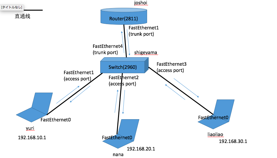
图1
这次实验的目的很简单就是实现不同网段之间的通讯,如图一所示我们有三台pc,分别叫做yuri,nana,liaoliao(三个我曾经追我的女孩的名字)。其中yuri属于10网段IP是:192.168.10.1,nana是属于20网段IP是:192.168.20.1,liaoliao是属于30网段,IP是192.168.30.1.我们最终的目的是在yuri上能够ping通nana和liaoliao。当然不同的网段就算是连在一台L2交换机上也是不能通讯的,就算连接路由,如果不进行相应的配置的话,路由器和交换机和搬砖也没什么区别。好吧,怎么配置呢,我们需要这样一个IMAGE.
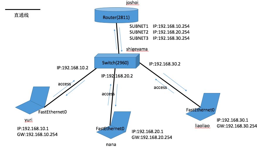
图2
图1,图2中我们可以看到,三台PC想要进行通讯需要路由器坐中继。yuri,nana,liaoliao分别连接的是交换机(switch)的三个access接口(FastEthernet1, FastEthernet2, FastEthernet3)。而交换机(switch)的第四个接口(FastEthernet4)连接的是路由器的第一个接口(FastEthernet1)。路由器和交换机之间的通讯因为要处理三台pc的信息,所以需要用trunk而不是access进行。路由器端的FastEthernet1接口因为不能同时添加多个IP所以需要对其添加三个子网IP来针对来自yuri,nana,liaoliao的三个网段的信息。这三个子网IP同时也是yuri,nana,liaoliao的网关。
废话别多说,赶紧进行实验。
Step1.
分别针对pc设定网关,IP地址,子网掩码。这里我们举个yuri的例子。
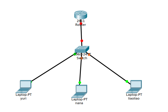
图3
双击图3中的yuri那台电脑,弹出设定画面,如下图4
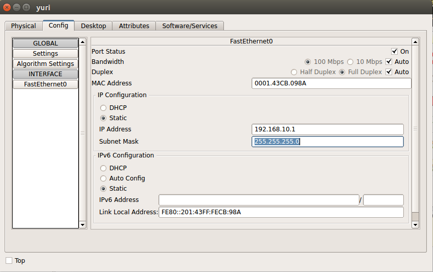
图4
上面的tab选择Config,左边的菜单setting里面设定网关为192.168.10.254,然后点击左边的菜单FastEthernet0设定IP Address 192.168.10.1以及Subnet Mast 255.255.255.0
然后对nana,liaoliao也做同样的操作
Step2.
对交换机(switch)设定vlan
点击图3中的交换机(switch),在弹出框中选择上面的CLI tab,命令行设定vlan,如图5
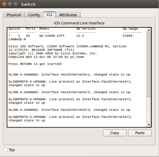
图5
输入以下命令,完成建立三个vlan,并且对其进行命名
Switch>
Switch>enable
Switch#conf t
Enter configuration commands, one per line.  End with CNTL/Z.
Switch(config)#
Switch(config)#vlan 10
Switch(config-vlan)#name yuri
Switch(config-vlan)#
Switch(config-vlan)#vlan 20
Switch(config-vlan)#name nana
Switch(config-vlan)#
Switch(config-vlan)#vlan 30
Switch(config-vlan)#name liaoliao
Step3.
对刚刚建立的vlan进行ip和子网掩码的分配,并且no shutdown
Switch(config-vlan)#int vlan 10
Switch(config-if)#
%LINK-5-CHANGED: Interface Vlan10, changed state to up

Switch(config-if)#ip address 192.168.10.2 255.255.255.0
Switch(config-if)#no sh
Switch(config-if)#int vlan 20
Switch(config-if)#
%LINK-5-CHANGED: Interface Vlan20, changed state to up

Switch(config-if)#ip address 192.168.20.2 255.255.255.0
Switch(config-if)#no sh
Switch(config-if)#
Switch(config-if)#
Switch(config-if)#int vlan 30
Switch(config-if)#
%LINK-5-CHANGED: Interface Vlan30, changed state to up

Switch(config-if)#ip address 192.168.30.2 255.255.255.0
Switch(config-if)#no sh
Step4.
针对交换机的连接pc的三个接口,给这三个接口赋予access mode,并对其赋予刚刚建立并且陪好IP的vlan
Switch(config)#int f0/1
Switch(config-if)#switchport mode access
Switch(config-if)#switchport access vlan 10
Switch(config-if)#
%LINEPROTO-5-UPDOWN: Line protocol on Interface Vlan10, changed state to up

Switch(config-if)#int f0/2
Switch(config-if)#switchport mode access
Switch(config-if)#switchport access vlan 20
Switch(config-if)#
%LINEPROTO-5-UPDOWN: Line protocol on Interface Vlan20, changed state to up

Switch(config-if)#
Switch(config-if)#int f0/3
Switch(config-if)#switchport mode access
Switch(config-if)#switchport access vlan 30
Switch(config-if)#
%LINEPROTO-5-UPDOWN: Line protocol on Interface Vlan30, changed state to up
Step5.
给交换机(switch)的第四个接口(连接路由器的接口)进行配置。需要其为trunk类型,并且允许创建的vlan10,vlan20,vlan30nenggou通过
Switch(config-if)#int f0/4
Switch(config-if)#switchport mode trunk
Switch(config-if)#switchport trunk allowed vlan 10,20,30
Step6.
给路由器的第一个接口(连接交换机的接口)进行配置。建立三个子网,分别对应三个vlan。并对三个子网进行ip和子网掩码的配置,然后no sh。
Router>enable
Router#conf t
Enter configuration commands, one per line.  End with CNTL/Z.
Router(config)#in f0/1
Router(config-if)#no sh

Router(config-if)#
%LINK-5-CHANGED: Interface FastEthernet0/1, changed state to up

Router(config-if)#
%LINEPROTO-5-UPDOWN: Line protocol on Interface FastEthernet0/1, changed state to up

Router(config-if)#in f0/1.10
Router(config-subif)#
%LINK-5-CHANGED: Interface FastEthernet0/1.10, changed state to up

%LINEPROTO-5-UPDOWN: Line protocol on Interface FastEthernet0/1.10, changed state to up

Router(config-subif)#encapsulation dot1Q 10
Router(config-subif)#ip address 192.168.10.254 255.255.255.0
Router(config-subif)#no sh
Router(config-subif)#int f0/1.20
Router(config-subif)#
%LINK-5-CHANGED: Interface FastEthernet0/1.20, changed state to up

%LINEPROTO-5-UPDOWN: Line protocol on Interface FastEthernet0/1.20, changed state to up

Router(config-subif)#encapsulation dot1Q 20
Router(config-subif)#ip address 192.168.20.254 255.255.255.0
Router(config-subif)#no sh
Router(config-subif)#int f0/1.30
Router(config-subif)#
%LINK-5-CHANGED: Interface FastEthernet0/1.30, changed state to up

%LINEPROTO-5-UPDOWN: Line protocol on Interface FastEthernet0/1.30, changed state to up

Router(config-subif)#encapsulation dot1Q 30
Router(config-subif)#ip address 192.168.30.254 255.255.255.0
Router(config-subif)#no sh
Step7.
测试
在yuri上对料料进行ping 192.168.30.1
C:\>ping 192.168.30.1

Pinging 192.168.30.1 with 32 bytes of data:

Request timed out.
Reply from 192.168.30.1: bytes=32 time<1ms TTL=127
Reply from 192.168.30.1: bytes=32 time=1ms TTL=127
Reply from 192.168.30.1: bytes=32 time<1ms TTL=127

Ping statistics for 192.168.30.1:
    Packets: Sent = 4, Received = 3, Lost = 1 (25% loss),
Approximate round trip times in milli-seconds:
    Minimum = 0ms, Maximum = 1ms, Average = 0ms
在nana上对liaoliao的交换机接口进行ping 192.168.30.2
C:\>ping 192.168.30.2

Pinging 192.168.30.2 with 32 bytes of data:

Request timed out.
Request timed out.
Reply from 192.168.30.2: bytes=32 time<1ms TTL=255
Reply from 192.168.30.2: bytes=32 time<1ms TTL=255

Ping statistics for 192.168.30.2:
    Packets: Sent = 4, Received = 2, Lost = 2 (50% loss),
Approximate round trip times in milli-seconds:
    Minimum = 0ms, Maximum = 0ms, Average = 0ms
在liaoliao上对yuri的网关进行ping 192.168.10.254
C:\>ping 192.168.10.254

Pinging 192.168.10.254 with 32 bytes of data:

Reply from 192.168.10.254: bytes=32 time<1ms TTL=255
Reply from 192.168.10.254: bytes=32 time<1ms TTL=255
Reply from 192.168.10.254: bytes=32 time<1ms TTL=255
Reply from 192.168.10.254: bytes=32 time<1ms TTL=255

Ping statistics for 192.168.10.254:
    Packets: Sent = 4, Received = 4, Lost = 0 (0% loss),
Approximate round trip times in milli-seconds:
    Minimum = 0ms, Maximum = 0ms, Average = 0ms
以上可以看到刚开始ping的时候前面两帧会有丢帧的现象,我还没有完全学明白。可能是arp的原因吧。
我也是刚开始学习ccna,肯定有不足的地方,希望以后会越变越好