はじめに
「Router-on-a-stick(ROAS)」は、異なるVLAN間のトラフィックについて、ルーティングを可能にするために使用されるネットワーク構成です。「one-armed router」とも呼ばれています。
VLANでは、基本的に互いを分離しています。このため、あるVLAN内のパケットが別のVLANに送信されることはありません。
そこで、VLAN間でパケットを転送するには、次の方法が考えられます。
- スイッチ上の各VLANに接続する外部ルータを用意しルーティングする
- LANスイッチに接続された単一のルータがもつVLANトランクリンクを介して各VLANへアクセスする
- L3スイッチにてルーティングする
VLAN Trunk
1台のスイッチに複数のVLANが存在している場合、それらをルーティングさせるためには、VLANの数だけルータのポートが必要となります。これでは、現実的な構成をとることができません。
スイッチであれば、単一のスイッチポートを介して複数のVLANを転送できる「trunk link」があります。しかし、ルータではトランクポートをサポートしていません。そこで、ルータでは「subinterface」を使用します。
ROASでは、IEEE 802.1Qトランクに接続されたVLANに関連付けられているサブネットにパケットをルーティングできるようにしています。ルータはトランク上の各VLANに関連付けられた複数の仮想インターフェイスを作成し、VLAN IDでタグ付けされたフレームをsubinterfaceで出入りできるように取り扱います。
シナリオ
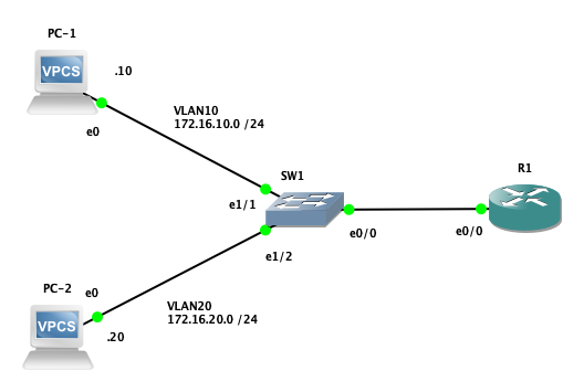
あなたは、R1の設定を担当しています。PC-1とPC-2は異なるVLANに配置されています。
PC-1とPC-2の接続性を回復してください。

条件
- ルーティングプロトコルを設定したり、スタティックルートを使用したりしないでください。
- R1に対して、追加のインターフェイスとIPアドレスを設定することが可能です。
- PC-1とPC-2がお互いにpingによる通信が確立することを確認してください。
事前設定:VPCSの設定
「PC-1」、「PC-2」それぞれに、IPアドレス、サブネットマスク、デフォルトゲートウェイを設定する。
PC-1> ip 172.16.10.10/24 172.16.10.1
Checking for duplicate address...
PC1 : 172.16.10.10 255.255.255.0 gateway 172.16.10.1

PC-1> save
Saving startup configuration to startup.vpc
.  done
PC-2> ip 172.16.20.20/24 172.16.20.1
Checking for duplicate address...
PC1 : 172.16.20.20 255.255.255.0 gateway 172.16.20.1

PC-2> save
Saving startup configuration to startup.vpc
.  done
事前設定:スイッチの構成
VLAN 10, 20の作成
まず、show vlan briefにて既存のvlanについて確認します。
SW1#show vlan brief

VLAN Name                             Status    Ports
---- -------------------------------- --------- -------------------------------
1    default                          active    Et0/0, Et0/1, Et0/2, Et0/3
                                                Et1/0, Et1/1, Et1/2, Et1/3
                                                Et2/0, Et2/1, Et2/2, Et2/3
                                                Et3/0, Et3/1, Et3/2, Et3/3
1002 fddi-default                     act/unsup
1003 token-ring-default               act/unsup
1004 fddinet-default                  act/unsup
1005 trnet-default                    act/unsup
次に、VLAN 10, 20の作成を行います。
SW1#config terminal
Enter configuration commands, one per line.  End with CNTL/Z.
SW1(config)#vlan 10,20
SW1(config-vlan)#exit
IPルーティングを無効化する
SW1#configure terminal
Enter configuration commands, one per line.  End with CNTL/Z.
SW1(config)#no ip routing
SW1(config)#exit
VLANをポートに割り当てる
次に、ポートe1/1にVLAN10を割り当て、ポートe1/2をVLAN20に割り当てます。
SW1(config)#interface ethernet 1/1
SW1(config-if)#switchport mode access
SW1(config-if)#switchport access vlan 10
SW1(config-if)#exit
SW1(config)#interface ethernet 1/2
SW1(config-if)#switchport mode access
SW1(config-if)#switchport access vlan 20
SW1(config-if)#exit
再び、show vlan briefにてVLAN 10,20のStatusがactiveであることを確認する。
SW1#show vlan brief

VLAN Name                             Status    Ports
---- -------------------------------- --------- -------------------------------
1    default                          active    Et0/0, Et0/1, Et0/2, Et0/3
                                                Et1/0, Et1/3, Et2/0, Et2/1
                                                Et2/2, Et2/3, Et3/0, Et3/1
                                                Et3/2, Et3/3
10   VLAN0010                         active    Et1/1
20   VLAN0020                         active    Et1/2
1002 fddi-default                     act/unsup
1003 token-ring-default               act/unsup
1004 fddinet-default                  act/unsup
1005 trnet-default                    act/unsup
トランクポートを設定する
ポートe0/0をトランクポートに設定する。トランクポートにはVLAN10, 20を許可する。
SW1#configure terminal
Enter configuration commands, one per line.  End with CNTL/Z.
SW1(config)#interface ethernet 0/0
SW1(config-if)#no ip address
SW1(config-if)#switchport mode trunk
SW1(config-if)#switchport trunk encapsulation dot1q
SW1(config-if)#switchport trunk allowed vlan add 10,20
SW1(config-if)#end
インターフェイスに設定を反映させる
SW1(config)#interface ethernet 0/0
SW1(config-if)#no shutdown
SW1(config-if)#exit
SW1(config)#interface ethernet 1/1
SW1(config-if)#no shutdown
SW1(config-if)#exit
SW1(config)#interface ethernet 1/2
SW1(config-if)#no shutdown
SW1(config-if)#exit
SW1#copy running-config startup-config
Destination filename [startup-config]?
Warning: Attempting to overwrite an NVRAM configuration previously written
by a different version of the system image.
Overwrite the previous NVRAM configuration?[confirm]
Building configuration...
Compressed configuration from 1499 bytes to 891 bytes[OK]
接続性の回復:ルータの設定
subinterfaceの作成
ルーティングするVLANごとに一意のsubinterfaceを作成します。グローバルコンフィグレーションモードで、 interface type number.subint を実行します。
まず、トランクポートを立ち上げます。
R1#configure terminal
Enter configuration commands, one per line.  End with CNTL/Z.
R1(config)#interface ethernet 0/0
R1(config-if)#no shutdown
R1(config-if)#end
R1#
e0/0にsubinterface「.10」を作成
R1#configure terminal
Enter configuration commands, one per line.  End with CNTL/Z.
R1(config)#interface ethernet 0/0.10
R1(config-subif)#encapsulation dot1Q 10
R1(config-subif)#ip address 172.16.10.1 255.255.255.0
R1(config-subif)#no shutdown
R1(config-if)#end
R1#
e0/0にsubinterface「.20」を作成
R1#configure terminal
Enter configuration commands, one per line.  End with CNTL/Z.
R1(config)#interface ethernet 0/0.20
R1(config-subif)#encapsulation dot1Q 20
R1(config-subif)#ip address 172.16.20.1 255.255.255.0
R1(config-subif)#no shutdown
R1(config-if)#end
R1#
ルーティングテーブルの確認
show ip routeコマンドを使用し、VLANサブネットへのルートがすでに確立されているか確認を行います。
R1#show ip route
Codes: L - local, C - connected, S - static, R - RIP, M - mobile, B - BGP
       D - EIGRP, EX - EIGRP external, O - OSPF, IA - OSPF inter area
       N1 - OSPF NSSA external type 1, N2 - OSPF NSSA external type 2
       E1 - OSPF external type 1, E2 - OSPF external type 2
       i - IS-IS, su - IS-IS summary, L1 - IS-IS level-1, L2 - IS-IS level-2
       ia - IS-IS inter area, * - candidate default, U - per-user static route
       o - ODR, P - periodic downloaded static route, H - NHRP, l - LISP
       a - application route
       + - replicated route, % - next hop override

Gateway of last resort is not set

      172.16.0.0/16 is variably subnetted, 4 subnets, 2 masks
C        172.16.10.0/24 is directly connected, Ethernet0/0.10
L        172.16.10.1/32 is directly connected, Ethernet0/0.10
C        172.16.20.0/24 is directly connected, Ethernet0/0.20
L        172.16.20.1/32 is directly connected, Ethernet0/0.20
最後に、設定を反映させます。
R1#copy running-config startup-config
Destination filename [startup-config]?
Building configuration...
[OK]
検証
別のVLANからpingを送信できるか確認します。VLAN 10に所属するPC-1からR1(172.16.10.1)に対して、疎通できるか確認します。
次に、PC-1からVLAN 20に所属するPC-2(172.16.20.20)に対して、疎通できるか確認します。
PC-1> ping 172.16.10.1
84 bytes from 172.16.10.1 icmp_seq=1 ttl=255 time=0.468 ms
84 bytes from 172.16.10.1 icmp_seq=2 ttl=255 time=0.659 ms
84 bytes from 172.16.10.1 icmp_seq=3 ttl=255 time=0.651 ms
84 bytes from 172.16.10.1 icmp_seq=4 ttl=255 time=0.588 ms
84 bytes from 172.16.10.1 icmp_seq=5 ttl=255 time=0.636 ms

PC-1> ping 172.16.20.20
84 bytes from 172.16.20.20 icmp_seq=1 ttl=63 time=2.342 ms
84 bytes from 172.16.20.20 icmp_seq=2 ttl=63 time=1.192 ms
84 bytes from 172.16.20.20 icmp_seq=3 ttl=63 time=1.136 ms
84 bytes from 172.16.20.20 icmp_seq=4 ttl=63 time=1.205 ms
84 bytes from 172.16.20.20 icmp_seq=5 ttl=63 time=1.110 ms
同様に、VLAN 20に所属するPC-2からR1(172.16.20.1)に対して、疎通できるか確認します。
次に、PC-2からVLAN 10に所属するPC-1(172.16.10.10)に対して、疎通できるか確認します。
PC-2> ping 172.16.20.1
84 bytes from 172.16.20.1 icmp_seq=1 ttl=255 time=0.549 ms
84 bytes from 172.16.20.1 icmp_seq=2 ttl=255 time=0.610 ms
84 bytes from 172.16.20.1 icmp_seq=3 ttl=255 time=4.451 ms
84 bytes from 172.16.20.1 icmp_seq=4 ttl=255 time=0.753 ms
84 bytes from 172.16.20.1 icmp_seq=5 ttl=255 time=1.789 ms

PC-2> ping 172.16.10.10
84 bytes from 172.16.10.10 icmp_seq=1 ttl=63 time=1.054 ms
84 bytes from 172.16.10.10 icmp_seq=2 ttl=63 time=0.873 ms
84 bytes from 172.16.10.10 icmp_seq=3 ttl=63 time=1.073 ms
84 bytes from 172.16.10.10 icmp_seq=4 ttl=63 time=1.035 ms
84 bytes from 172.16.10.10 icmp_seq=5 ttl=63 time=1.145 ms
まとめ
シスコ製ルータとスイッチ間でIEEE 802.1Qトランクリンクを設定する方法を確認しました。Router-on-a-stick設定は、レイヤ3スイッチングがない環境で主に使用されます。これは、単一のルータと1つのインターフェイスを使用してVLAN間ルーティングサービスが提供でき、費用効率が高いためです。