この記事は記事「ESP-WROOM-02 + ArduinoOTAでスケッチのWiFi経由アップロード」を参考にさせていただきました。ありがとうございます ![]()
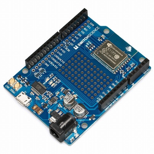
スイッチサイエンス製 ESP-WROOM-02 Arduino互換ボード
スイッチサイエンスからESP-WROOM-02 Arduino互換ボードが発売されました。今まではESP-WROOM-02(ESP8266)をArduinoのスケッチを書き込んで使うためには、モジュールをはんだ付けしてブレッドボード上で使用したりと少々使いづらい部分がありました。それをこの互換ボードが解消してくれます ![]()
ArduinoOTAを使うとWi-Fi経由でスケッチを書き込める!
OTA(Over the Air)とは、「無線通信を経由して」という意味の英語表現で、これまで外部記憶装置や有線通信で行われてきたデータの送受信などが無線通信に対応した場合などによく用いられる表現。
OTAとは - IT用語辞典より引用
Arduinoでは、パソコンとUSBケーブルで接続していたところを、Wi-Fiで無線接続するというものです。ですので、USBケーブルいらずで書き込めるようになります(無線化するスケッチはUSB接続で書き込む必要あり)。
実現手順
Wi-Fi経由でスケッチを書き込むまでの手順です。
- 開発環境の構築
- USBケーブル経由で互換ボードにOTAのサンプルスケッチを書き込む
- USBケーブルを抜きWi-Fi接続
- Arduino IDEで同一ネットワーク上の互換ボードを選択
- Wi-Fi経由で書き込み!
開発環境の構築
Arduino IDEとESP8266のライブラリは既にインストール済みというところからはじめます。Arduino IDEの他に必要になるのがPythonです。バージョンは2.7をインストールしてください。
ダウンロードリンク
USBケーブル経由で互換ボードにOTAのサンプルスケッチを書き込む
早速Wi-Fi経由でスケッチを書き込みたいところですが、そのままでは互換ボードに対して何も設定していない状態のため書き込めません。いろいろ突っ込みたいところは抑えつつ、USB経由でOTA用のスケッチを互換ボードに書き込みます。Arduino IDEのメニューから[ファイル]→[スケッチの例]→[ArduinoOTA]→[BasicOTA]をクリックしサンプルスケッチを開きます。スケッチ内のssidとpasswordを適宜変更して書き込みます。
# include <ESP8266WiFi.h>
# include <ESP8266mDNS.h>
# include <WiFiUdp.h>
# include <ArduinoOTA.h>

const char* ssid = "..........";
const char* password = "..........";

void setup() {
  Serial.begin(115200);
  Serial.println("Booting");
  WiFi.mode(WIFI_STA);
  WiFi.begin(ssid, password);
  while (WiFi.waitForConnectResult() != WL_CONNECTED) {
    Serial.println("Connection Failed! Rebooting...");
    delay(5000);
    ESP.restart();
  }

  // Port defaults to 8266
  // ArduinoOTA.setPort(8266);

  // Hostname defaults to esp8266-[ChipID]
  // ArduinoOTA.setHostname("myesp8266");

  // No authentication by default
  // ArduinoOTA.setPassword((const char *)"123");

  ArduinoOTA.onStart([]() {
    Serial.println("Start");
  });
  ArduinoOTA.onEnd([]() {
    Serial.println("\nEnd");
  });
  ArduinoOTA.onProgress([](unsigned int progress, unsigned int total) {
    Serial.printf("Progress: %u%%\r", (progress / (total / 100)));
  });
  ArduinoOTA.onError([](ota_error_t error) {
    Serial.printf("Error[%u]: ", error);
    if (error == OTA_AUTH_ERROR) Serial.println("Auth Failed");
    else if (error == OTA_BEGIN_ERROR) Serial.println("Begin Failed");
    else if (error == OTA_CONNECT_ERROR) Serial.println("Connect Failed");
    else if (error == OTA_RECEIVE_ERROR) Serial.println("Receive Failed");
    else if (error == OTA_END_ERROR) Serial.println("End Failed");
  });
  ArduinoOTA.begin();
  Serial.println("Ready");
  Serial.print("IP address: ");
  Serial.println(WiFi.localIP());
}

void loop() {
  ArduinoOTA.handle();
}
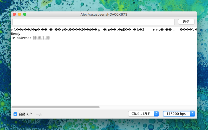
Wi-Fiに接続できると次のようにシリアルモニターへ表示されます。ESP-WROOM-02に割り当てられたIPアドレスとともに。
Arduino IDEで同一ネットワーク上のESP-WROOM-02を選択
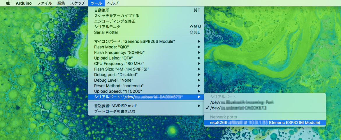
Wi-Fi経由で書き込むためにはいくつか設定が必要です。まず、ESP-WROOM-02が接続されているポートを変更します。Arduino IDEのメニューから[ツール]→[ポート]→[Network ports esp8266-〜〜〜]をクリックします。表示されていない場合は、Arduino IDEを再起動するか、ESP-WROOM-02がWi-Fiへ接続できるまで待ちます。次に、OTAで書き込むので[ツール]→[Upload Using]→[OTA]を選択します。
Wi-Fi経由で書き込み!
ここで1点注意するポイント。それは先ほど書き込んだBasicOTAのサンプルスケッチを基に、OTAの処理を残したままスケッチを開発するということです。OTAの処理がなくなってしまうと、Wi-Fi経由で書き込めなくなるというシンプルな理由です。ですのでOTAの処理が増える分、スケッチのデータ容量が増えてしまいます。次のソースコードをご覧のとおり、OTAの処理にLチカの処理を加えています。
# include <ESP8266WiFi.h>
# include <ESP8266mDNS.h>
# include <WiFiUdp.h>
# include <ArduinoOTA.h>

const char* ssid = "..........";
const char* password = "..........";

void setup() {
  Serial.begin(115200);
  Serial.println("Booting");
  WiFi.mode(WIFI_STA);
  WiFi.begin(ssid, password);
  while (WiFi.waitForConnectResult() != WL_CONNECTED) {
    Serial.println("Connection Failed! Rebooting...");
    delay(5000);
    ESP.restart();
  }

  // Port defaults to 8266
  // ArduinoOTA.setPort(8266);

  // Hostname defaults to esp8266-[ChipID]
  // ArduinoOTA.setHostname("myesp8266");

  // No authentication by default
  // ArduinoOTA.setPassword((const char *)"123");

  ArduinoOTA.onStart([]() {
    Serial.println("Start");
  });
  ArduinoOTA.onEnd([]() {
    Serial.println("\nEnd");
  });
  ArduinoOTA.onProgress([](unsigned int progress, unsigned int total) {
    Serial.printf("Progress: %u%%\r", (progress / (total / 100)));
  });
  ArduinoOTA.onError([](ota_error_t error) {
    Serial.printf("Error[%u]: ", error);
    if (error == OTA_AUTH_ERROR) Serial.println("Auth Failed");
    else if (error == OTA_BEGIN_ERROR) Serial.println("Begin Failed");
    else if (error == OTA_CONNECT_ERROR) Serial.println("Connect Failed");
    else if (error == OTA_RECEIVE_ERROR) Serial.println("Receive Failed");
    else if (error == OTA_END_ERROR) Serial.println("End Failed");
  });
  ArduinoOTA.begin();
  Serial.println("Ready");
  Serial.print("IP address: ");
  Serial.println(WiFi.localIP());

  pinMode(14, OUTPUT);
}

void loop() {
  ArduinoOTA.handle();

  // Lチカの処理
  digitalWrite(14, HIGH);

  delay(1000);

  digitalWrite(14, LOW);

  delay(1000);
}
開発中はWi-Fi経由でいいが本番はUSBで書き込んだほうがいいかも
個人的な主観ですが、このOTAを使ったWi-Fi経由での書き込みは主に開発中に使うものかと感じました。スケッチのアップロードにかかる時間も、USBケーブル使用時より速いです。一通り開発が完了した時点で、OTAの処理をスケッチから省いて書き込むとムダも省けて安心です。