はじめに
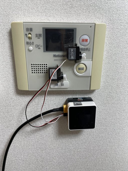
作りたいものはこのタイトルと以下の写真を見てもらえたらなんとなく察してもらえるのでは?と思っています。
私の住んでいるアパートのピンポンに出るための通話ボタンと入り口のオートロックを開けるための解錠ボタンを自動で押してくれるためのデバイスを作りたい!というわけです。なおかつそれをAlexaで操作したいと考えています。
使用したもの
使用したハードウェアは以下の通りです。
テンション上がる pic.twitter.com/xtrchhHIzy
— ゆーふぉーろくはち (@ufoo_yuta) November 27, 2021
開発環境のセットアップ
今回はm5stackの開発環境をvscodeとPlatformIOを使って開発を行います。少し昔はArduinoの拡張を使っていたりしていたのですが、ライブラリの管理の便利さやgit管理のやりやすさの観点から個人的にはPlatformIOの方が便利だと思っています。
今回は以下のライブラリを用いています。
- adafruit/Adafruit PWM Servo Driver Library@^2.4.0
- m5stack/M5Core2@^0.0.9
- vintlabs/FauxmoESP@^3.4
- me-no-dev/AsyncTCP@^1.1.1
実装
ソースコード全体はGitHubにすべて公開しております。
サーボモーターを動かす
公式が用意してくれたサンプルコードを拝借します。基本的にサーボモーターはPWMと呼ばれる一定周期でONになっている電圧を信号として角度制御を行ったりしている1のですが、ここでは詳細は説明しません。とにかくPWMというやつを指定する必要があるのですが、そんなハードウェアあたりを意識したくない人(私とか)としては直接角度を指定してサーボを制御したいわけです。
そのための関数(servo_angle_write)を以下のコードをコピペすることで作成することができます。
# include <Adafruit_PWMServoDriver.h>

Adafruit_PWMServoDriver pwm = Adafruit_PWMServoDriver(0x40, Wire);

# define SERVOMIN 102  // This is the 'minimum' pulse length count (out of 4096)
# define SERVOMAX 512  // This is the 'maximum' pulse length count (out of 4096)
# define USMIN 500     // This is the rounded 'minimum' microsecond length based on the minimum pulse of 102
# define USMAX 2500    // This is the rounded 'maximum' microsecond length based on the maximum pulse of 512
# define SERVO_FREQ 50 // Analog servos run at ~50 Hz updates

void setServoPulse(uint8_t n, double pulse)
{
  double pulselength;
  pulselength = 1000000; // 1,000,000 us per second
  pulselength /= 50;     // 50 Hz
  Serial.print(pulselength);
  Serial.println(" us per period");
  pulselength /= 4096; // 12 bits of resolution
  Serial.print(pulselength);
  Serial.println(" us per bit");
  pulse *= 1000;
  pulse /= pulselength;
  Serial.println(pulse);
  pwm.setPWM(n, 0, pulse);
}

void servo_angle_write(uint8_t n, int Angle)
{
  double pulse = Angle;
  pulse = pulse / 90 + 0.5;
  setServoPulse(n, pulse);
}

// この関数をsetup()で呼び出す
void servoSetup() {
  pwm.begin();
  pwm.setPWMFreq(50);
}

void setup()
{
  // https://docs.m5stack.com/en/module/servo2?id=module-servo-2
  M5.begin(true, true, true, false, kMBusModeInput);
  // servo2 moduleの対応Pinに合わせるため
  Wire.begin(21, 22);
  servoSetup();
}
ちなみにsetup内で行った初期設定↓は、M5Stack Core2でM5Stack用Servo2モジュールを使う場合には必要となるので、必ず設定しておきましょう。
M5.begin(true, true, true, false, kMBusModeInput);
Wire.begin(21, 22);
サーボ動いた pic.twitter.com/lBkJAJoRKF
— ゆーふぉーろくはち (@ufoo_yuta) November 30, 2021
OTAを設定する
基本的にマイコンの開発はUSBケーブルをつないだ状態でプログラムを書き込むのが普通なのですが、一々マイコンをケーブルにつなぐのは面倒なわけです。
そこで用いるのがOTAという仕組みで、これを用いるとWiFi経由でプログラムの書き込みを行うことができます。2
導入方法はとても簡単で、以下のコードを追加するだけです。
# include <WiFi.h>
# include <ArduinoOTA.h>
# include "wifi_setting.h"

void wifiSetup()
{
  WiFi.mode(WIFI_STA);
  WiFi.begin(WIFI_SSID, WIFI_PASS);
  while (WiFi.status() != WL_CONNECTED)
  {
    Serial.print(".");
    delay(100);
  }
  Serial.println();
  Serial.printf("[WIFI] STATION Mode, SSID: %s, IP address: %s\n", WiFi.SSID().c_str(), WiFi.localIP().toString().c_str());
}

// setup内で呼び出す
void otaSetup()
{
  ArduinoOTA.setHostname("m5stack-core2");

  ArduinoOTA
      .onStart([]()
               {
                 String type;
                 if (ArduinoOTA.getCommand() == U_FLASH)
                   type = "sketch";
                 else // U_SPIFFS
                   type = "filesystem";
                 Serial.println("Start updating " + type);
               })
      .onEnd([]()
             { Serial.println("\nEnd"); })
      .onProgress([](unsigned int progress, unsigned int total)
                  { Serial.printf("Progress: %u%%\r", (progress / (total / 100))); })
      .onError([](ota_error_t error)
               {
                 Serial.printf("Error[%u]: ", error);
                 if (error == OTA_AUTH_ERROR)
                   Serial.println("Auth Failed");
                 else if (error == OTA_BEGIN_ERROR)
                   Serial.println("Begin Failed");
                 else if (error == OTA_CONNECT_ERROR)
                   Serial.println("Connect Failed");
                 else if (error == OTA_RECEIVE_ERROR)
                   Serial.println("Receive Failed");
                 else if (error == OTA_END_ERROR)
                   Serial.println("End Failed");
               });

  ArduinoOTA.begin();
}

void setup()
{
  wifiSetup();
  otaSetup();
}
ちなみにwifiSetup()としてwifiの初期設定のコードを実装しております。OTAを使うためには当然、wifiに接続させる必要があります。
また、OTA用の環境を設定する必要があるので、PlatformIOの設定ファイルを以下のように追加で作成しました。
[env:m5stack-core2]
platform = espressif32
board = m5stack-core2
framework = arduino
monitor_speed = 115200
lib_deps =
	adafruit/Adafruit PWM Servo Driver Library@^2.4.0
	m5stack/M5Core2@^0.0.9
	vintlabs/FauxmoESP@^3.4
	me-no-dev/AsyncTCP@^1.1.1

[env:m5stack-core2_ota]
platform = espressif32
board = m5stack-core2
framework = arduino
lib_deps =
	adafruit/Adafruit PWM Servo Driver Library@^2.4.0
	m5stack/M5Core2@^0.0.9
	vintlabs/FauxmoESP@^3.4
	me-no-dev/AsyncTCP@^1.1.1
monitor_speed = 115200
upload_protocol = espota
upload_port = m5stack-core2
[env:m5stack-core2_ota]が今回OTA用に追加した項目です。
Alexaデバイスとして登録する
Alexaデバイスとして登録をすることでAlexaのアプリからM5Stack Core2を操作することができます。そのためにfauxmoESPというライブラリを用います。3
まずは以下のコードを追加します。
# include <fauxmoESP.h>

// setup内で呼び出す
void alexaDeviceSetup()
{
  fauxmo.createServer(true);
  fauxmo.setPort(80);
  fauxmo.enable(true);
  fauxmo.addDevice("intercom");
  fauxmo.addDevice("door");
  fauxmo.onSetState([](unsigned char device_id, const char *device_name, bool state, unsigned char value)
                    {
                      Serial.printf("[MAIN] Device #%d (%s) state: %s value: %d\n", device_id, device_name, state ? "ON" : "OFF", value);
                      servo_angle_write(device_id, 90);
                      delay(500);
                      servo_angle_write(device_id, 70);
                      delay(500);
                      servo_angle_write(device_id, 90);
                    });
}

void setup()
{
  alexaDeviceSetup();
}
fauxmo.addDevice()でAlexaデバイスとして登録するデバイス名を設定します。どうやら複数設定できるようです。設定をするとAlexaのアプリからデバイスへ接続できます。
fauxmoはデバイスをライトとしてAlexaデバイスに認識させるためのライブラリとなっています。なので、見かけ上はPhilips HueとしてライトのON/OFFや明るさ制御の命令をAlexaから受け取ることができます。この制御命令を利用してサーボモーターの動作スイッチとすることとします。この処理内容はfauxmo.onSetStateで記載しています。
以上でAlexaとM5Stack Core2の連携が実現できました。
Alexaと連携できた pic.twitter.com/aEmmY2ISLV
— ゆーふぉーろくはち (@ufoo_yuta) November 30, 2021
さいごに
後はサーボモーターの動作角度とかを微調整しながら実証実験だと思っていたのですが、ここで悲劇が起きました
剥がれたwww pic.twitter.com/8gprKwzC4n
— ゆーふぉーろくはち (@ufoo_yuta) November 30, 2021
まあ、そりゃそうだなと思ったわけですがwww
M5Stack Core2がいろんなモジュールを重ねて重くなったので、壁への取り付けを一旦諦めました。。。
んで、m5stackの方は壁への張り付けを諦めた。
— ゆーふぉーろくはち (@ufoo_yuta) December 3, 2021
何とも情けない pic.twitter.com/0IuiLDJoeB
とりあえず動けばいいやと思い、サーボを一旦動かしてみます。
実証実験してないけどわかる。これ多分押せてない pic.twitter.com/r7kLgaNAgN
— ゆーふぉーろくはち (@ufoo_yuta) December 3, 2021
正直サーボモーターを壁紙で貼れる用の剥離両面テープで固定していたので、当然そうなるとは思っていましたwww
結局一番難関かと思われる壁への取り付け方法という課題を残してしまったのですが、ソフトウェアとしてはだいたいやることをやった気がするので一旦記事にまとめてみました。再掲しますがコードは↓にすべて公開しております。サーボモーター制御のみに留まらず、色んなことに応用できると思うので是非試してみてください!!

