はじめに
同じIPアドレスを持つ2つのネットワーク(ブランチオフィス、VPC)をAWS上のForitgateVMに収容するとともに、Transit Gateway Connect上のマルチルートテーブルを利用したVRFルーティングを構築する手法を紹介します。なお本記事ではFortigateVM~Transit Gateway Connect間のBGP over GREにフォーカスしており、FortiGateVM~FortiGate間のVPNは本記事では省略しております。
トポロジー
考案した構成は以下です。テナントAのブランチとVPC、およびテナントBのブランチとVPCがそれぞれ同じネットワークアドレスを持っていることに注目してください。同一テナントのブランチ~VPC間の通信が可能なネットワークを構成し、テナント間の通信は一切行えないこととします。
Transit Gatewayは1つだけ作成すればよく、ルーティングテーブルを各VRFごとに分離して構成します。
テナントA(VRF11)
ブランチ:192.168.2.0/24
VPC:172.16.1.0/24
テナントB(VRF12)
ブランチ:192.168.2.0/24
VPC:172.16.1.0/24

FortiGateVMをHA構成でデプロイする
HA構成のFortiGateVMデプロイまでの手順はこちらの記事を参照してください。
FortiGateVMとブランチのFortiGate間でVRFルーティングを構成する
VRFごとにIPsecVPNを張り、トンネル上でBGPを動作させます。詳細はFortiGateのDocumentを参照してください。このとき、各インターフェースに適切にVRFを設定します。
config system interface
    edit "port1"
        set vrf 1
    next
    edit "port2"
        set vrf 11
    edit "port5"
        set vrf 12
    next
    edit "Lo"
        set vrf 1
    next
FortiGateVMでBGP over GREを構成する
Transit Gateway ConnectピアとのBGP over GREを構成します。耐障害性を高めるためにはTransit Gateway ConnectピアとのGREトンネルを2本ずつ張る必要がありますが、ここでは2本目の定義を省略しています。インターフェースやBGPコンフィグにおいて、FortiGateVM内のルートテーブルをVRFごとに分割する定義を忘れないようにしましょう。
config system gre-tunnel
    edit "tgwc11"
        set interface "port2"
        set remote-gw 192.168.1.1
        set local-gw 10.0.2.11
    next
    edit "tgwc12"
        set interface "port5"
        set remote-gw 192.168.1.2
        set local-gw 10.0.5.11
    next
end
config system interface
    edit "tgwc11"
        set vrf 11
        set ip 169.254.101.1 255.255.255.255
        set type tunnel
        set remote-ip 169.254.101.2 255.255.255.248
        set interface "port2"
    next
    edit "tgwc12"
        set vrf 12
        set ip 169.254.102.1 255.255.255.255
        set type tunnel
        set remote-ip 169.254.102.2 255.255.255.248
        set interface "port5"
    next
end
config router static
    edit 10
        set dst 192.168.101.0 255.255.255.0
        set gateway 10.0.2.1
        set device "port2"
    next
    edit 20
        set dst 192.168.101.0 255.255.255.0
        set gateway 10.0.5.1
        set device "port5"
    next
end
config router bgp
    set as 65001
    set router-id 10.200.1.11
    set keepalive-timer 1
    set holdtime-timer 3
    set ebgp-multipath enable
    set ibgp-multipath enable
    set recursive-next-hop enable
    set recursive-inherit-priority enable
    config neighbor
        edit "169.254.101.2"
            set advertisement-interval 1
            set ebgp-enforce-multihop enable
            set next-hop-self enable
            set soft-reconfiguration enable
            set interface "tgwc11"
            set remote-as 65200
            set update-source "tgwc11"
        next
        edit "169.254.102.2"
            set advertisement-interval 1
            set capability-default-originate enable
            set ebgp-enforce-multihop enable
            set next-hop-self enable
            set soft-reconfiguration enable
            set interface "tgwc12"
            set remote-as 65200
            set update-source "tgwc12"
        next
    end
    config vrf
        edit "1"
            set role pe
        next
        edit "11"
            set role ce
            set rd "65000:11"
            set export-rt "65000:11"
            set import-rt "65000:11"
        next
        edit "12"
            set role ce
            set rd "65000:12"
            set export-rt "65000:12"
            set import-rt "65000:12"
        next
    end
end
Transit Gatewayを作成する
Transit Gatewayを作成します。デフォルトルートテーブルの関連付けや伝播は無効にしておきましょう。

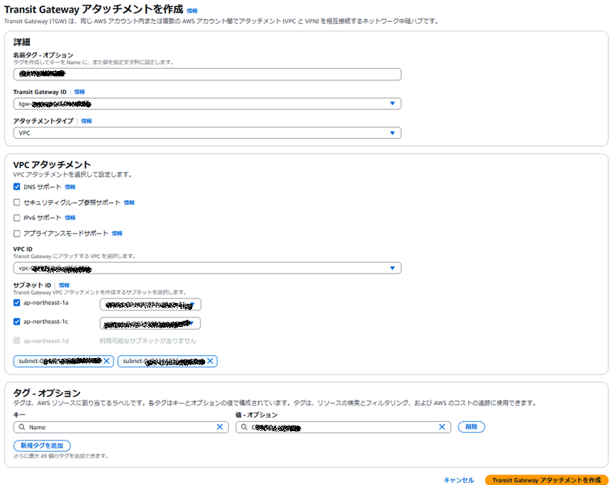
各種Transit Gateway VPCアタッチメントを作成する
FortiGateVMがデプロイされているVPCと、各テナントVPCにVPCアタッチメントを作成します。
Transit Gateway ConnectアタッチメントをテナントVRFの数だけ作成する
FortiGateVMとBGP over GREを構成するためのTransit Gateway ConnectアタッチメントをVRF11用とVRF12用にそれぞれ作成します。この時のトランスポートアタッチメントはFortiGateVMのVPCに作成したVPCアタッチメントを設定しましょう。

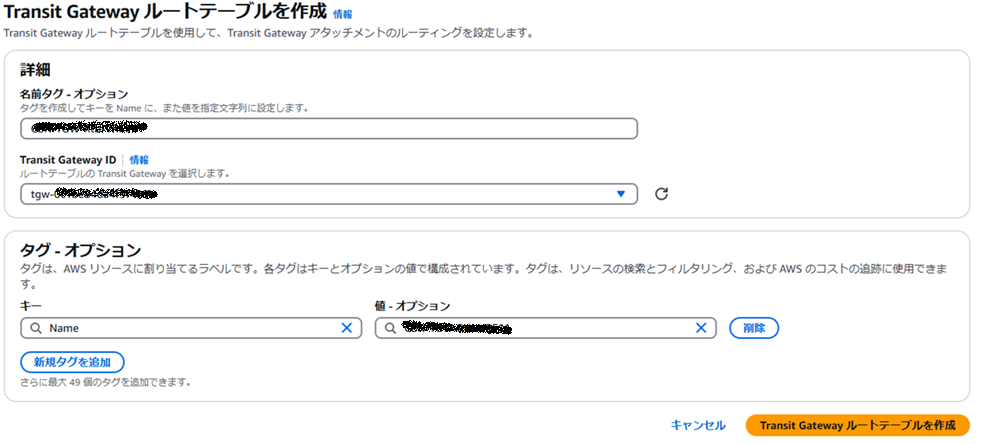
Transit Gateway ルートテーブルをテナントVRFの数だけ作成する
各VRF用にTransit Gateway ルートテーブルを作成します。作成したTransit Gateway ルートテーブルへ各VRF用に作成したTransit Gateway Connectアタッチメントを関連付けし、さらに伝播を有効化します。この時、FortiGateVMがデプロイされているVPCに各VRFと通信が必要なサーバなどが存在していなければ、FortiGateVMのデプロイされているVPCアタッチメントは関連付けや伝播の必要はありません。今回の要件はあくまで同一テナントのブランチ~VPC間の通信のみです。
Transit Gateway ConnectピアをVRFの数だけ作成する
Transit Gateway ConnectピアをVRFごとに作成します。

VPCのルートテーブルとFortiGateVMのセキュリティグループを編集する
FortiGateVMのピアGREアドレスとなるインターフェースが存在するサブネットのルートテーブルを編集します。また、FortiGateVMのセキュリティグループにGRE用の許可エントリを追加します。※許可エントリが無くてもTGW側からの通信開始でGREは成立します。

BGP over GREの確認
ここまでの設定でFortiGateVMとTransit Gateway Connect間のBGP over GREが確立します。各VRF用のTransit GatewayルートテーブルにFortiGateVMから学習した経路が伝搬されていることを確認しましょう。

FortiGateVM上の各VRFルーティングテーブルも確認しましょう。今回FortiGateVMに構成したVRFルーティング設定では、VRF:0とVRF:1をIPsecVPNやBGPピアの確立だけに使用しており、各テナントのルート情報は各テナント用のVRFにだけ学習されます。これによりテナント間の通信ができないネットワークを構成できます。
FGVM16TMxxxxxxxxxx # get router info routing-table all

Routing table for VRF=0
C       10.0.3.0/24 is directly connected, port3
C       10.0.4.0/24 is directly connected, port4

Routing table for VRF=1
S*      0.0.0.0/0 [1/0] via 10.0.1.1, port1, [1/0]
C       10.0.1.0/24 is directly connected, port1
C       10.200.1.11/32 is directly connected, Lo
S       10.200.1.250/32 [15/0] via advpn tunnel 10.200.1.250, [1/0]

Routing table for VRF=11
C       10.0.2.0/24 is directly connected, port2
C       169.254.101.0/29 is directly connected, tgwc
C       169.254.101.1/32 is directly connected, tgwc
B       192.168.0.0/16 [200/100] via 169.254.101.2 (recursive is directly connected, tgwc), 00:06:39, [1/0]
S       192.168.1.0/24 [10/0] via 10.0.2.1, port2, [1/0]
B V     192.168.2.0/24 [200/0] via 10.200.1.250 (recursive via advpn tunnel 10.200.1.250 [1]), 03:59:43, [1/0]
テナントVPCのルートテーブルを設定する
各テナントVPCのルートテーブルにおいてブランチネットワークアドレスを宛先としTransit Gatewayをターゲットとするルートエントリを定義します。ここまでの設定を完了すると各VRFにおけるブランチ~VPC間の通信が可能となり、異なるVRF間の通信ができないネットワークの完成となります。
Tips
各テナントのVPC CIDRにブランチのネットワークアドレスが含まれないように、AWSとオンプレミス全体において適切なアドレス設計が必要になります。
まとめ
VRFルーティング環境におけるFortigateVM~Transit Gateway Connect間のBGP over GREを構成する手法について紹介しました。VRFが増えるとその分だけ各コンポーネントの定義を増やす必要がありますが、各VRF内ブランチのルート情報はTransit GatewayルートテーブルまでBGPで動的に学習されるので高いスケーラビリティを持っています。1組のForitgateVMだけでマルチVRF環境を実現したい場合に適したソリューションだと思います。今後はCloud WANで今回の要件を満たせるか試してみたいと思います。