はじめに
寒風吹きすさぶ東京の空の下、昨夜徹夜で読み込んだ「インターフェース1月号」のP46の記事
「実験研究:注目AIコンパイラで広がる組み込み人工知能の世界」
の内容が面白く、是非、ピンク色のPYNQ-Z1というFPGAボードを手に入れたくて、秋葉原に行ってきました。
お店の人に聞くと、「FPGA入れとくと聞いているだけで、詳細は分かりません」とのこと。
でも、香港から空輸で調達するしかなかった時代もあると聞くので、地下鉄とJRでその日のうちに入手できるのはとてもありがたいし、エキサイティングです。
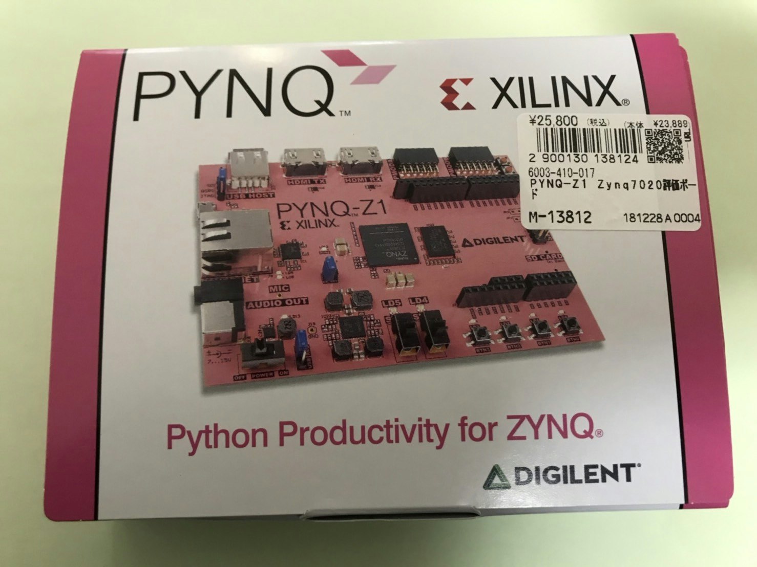
開封の儀
値段はシールが貼ってあるので分かりますが(w)、25,800円でした。ま、もちろんラズパイ(大体、5,800円くらい)と比べれば、4倍強なので高く感じます。結構、悩んでいる自分が可愛かったです。
でも、ラズパイではひっくり返っても不可能なことが出来ちゃう訳で、それを考えるとワクワクして、高さを和らげてくれますよね。
おお!ホンマにピンクやんけ。w
可愛い。
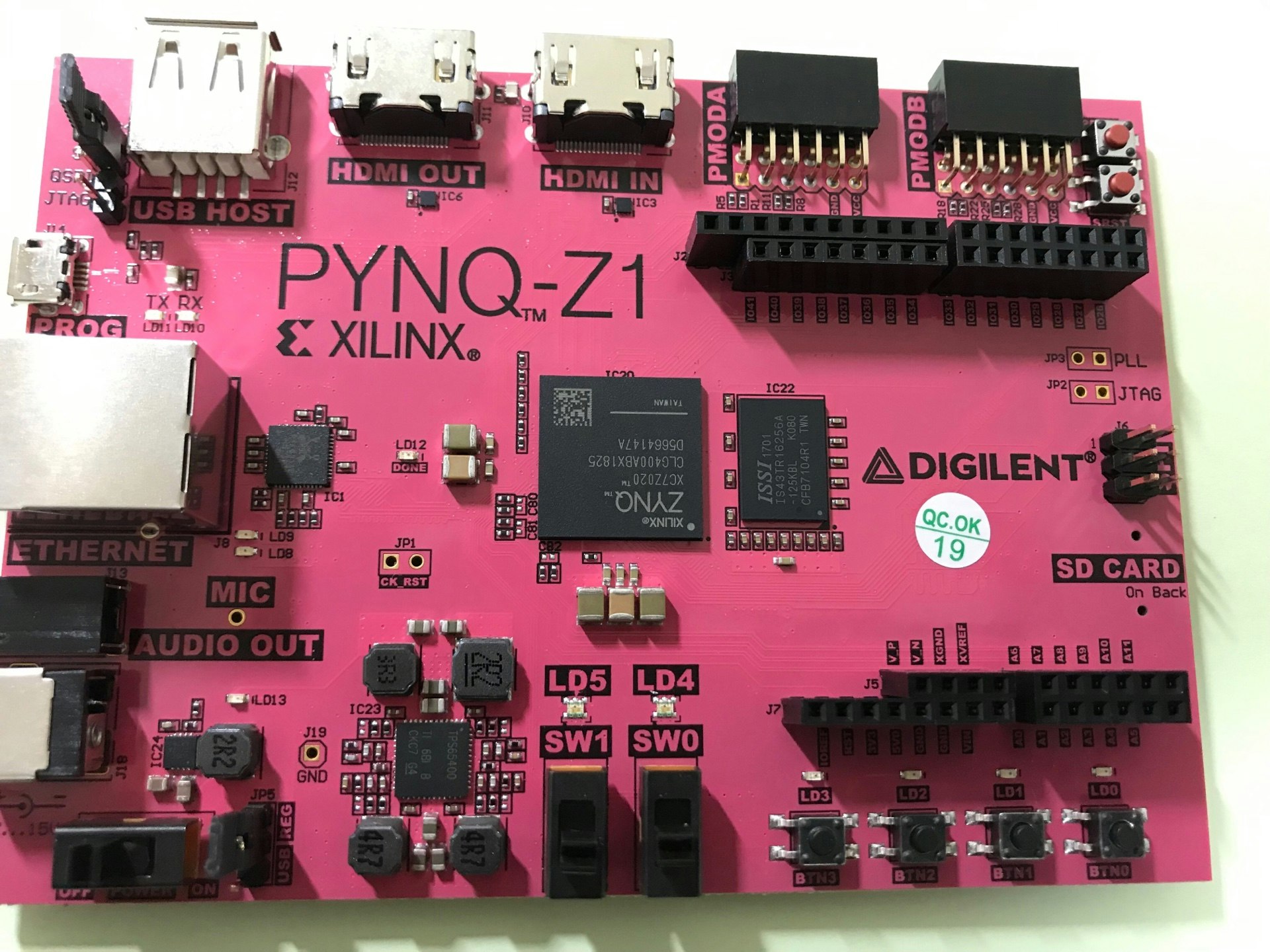
PYNQ-Z1の概要

1.Set the JP4 / Boot jumper to the SD position by placing the jumper over the top two pins of JP4 as shown in the image. (This sets the board to boot from the Micro-SD card)
2.To power the PYNQ-Z1 from the micro USB cable, set the JP5 / Power jumper to the USB position by placing the jumper over the top two pins as shown in the image. (You can also power the board from an external 12V power regulator by setting the jumper to REG.)
3.Insert the Micro SD card loaded with the PYNQ-Z1 image into the Micro SD card slot underneath the board.
4.Connect the USB cable to your PC/Laptop, and to the PROG - UART / J14 MicroUSB port on the board
5.Connect the board to Ethernet by following the instructions in Ethernet Setup
6.Turn on the PYNQ-Z1 by following the instructions in Turning On the PYNQ-Z1
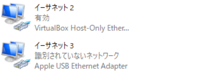
Ethernetの設定(Windows10編)
さてLANケーブルでEthernetに繋げないとだめらしいのですが、今私のPC(Win,Macとも) LANのポートは無いので、手持ちの AppleのUSB Ethernet Adapterを使います。ただ、これもすぐには認識してくれませんでした。
調べたところ、
Windows 10 のマシンでApple純正のUSBEthernetアダプタを使う方法
を参考に、Boot Camp Support Software 5.1.5621
というのを落とし、その中の、
\BootCamp5.1.5621.zip\BootCamp\Drivers\Asix\AsixSetup64.exe
を実行したところ、【イーサネット】という名前で、認識してくれました。
イーサネットプロパティの設定
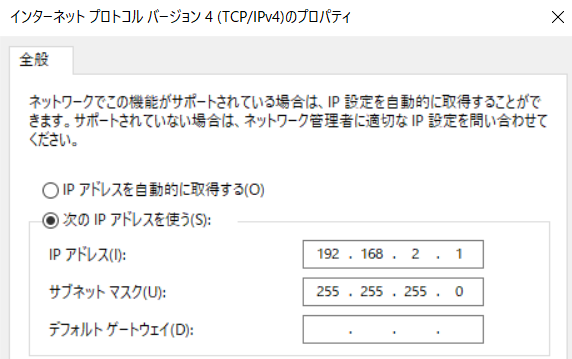
PYNQは、デフォルトで
192.168.2.99
が自身のIPとしているようで、【イーサネット】も同じIPレンジで以下のように
設定する必要があります。
IPv4:192.168.2.1
subnet mask : 255.255.255.0
プロパティ設定のダイアログで
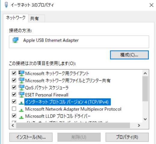
[インターネットプロトコルバージョン4(TCP/IPv4)]->[詳細設定]
と設定します。
これで、 Apple USB Ethernet Adapterが無事認識されます。
起動イメージの準備
詳細な原文のチュートリアルはこちらから。
https://pynq.readthedocs.io/en/v2.0/appendix.html#writing-the-sd-card
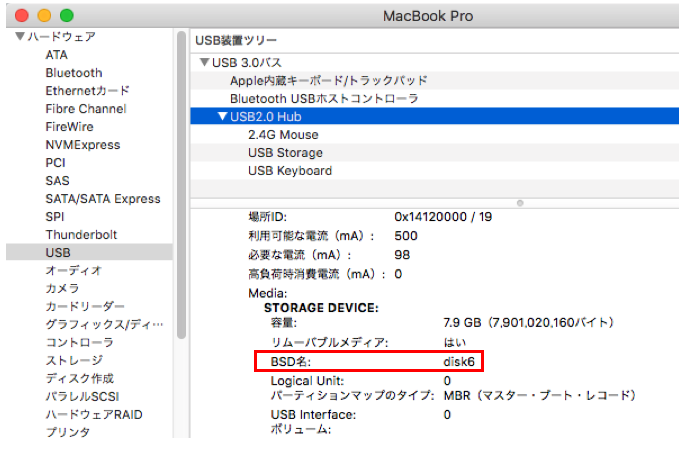
SDカードのMacでのデバイス名を調べます。
「Appleマーク」->「このMacについて」->「システムレポート」->「USB」
で右欄のBSD名を見ます。私の場合は、disk6でした。
diskutil list
/dev/disk6 (external, physical):
   #:                       TYPE NAME                    SIZE       IDENTIFIER
   0:     FDisk_partition_scheme                        *7.9 GB     disk6
   1:             Windows_FAT_32 NO NAME                 104.9 MB   disk6s1
   2:                      Linux                         4.0 GB     disk6s2
調べたところ、最低8Gで良いということで、そのようになっていますね。
次にここから、イメージを落とします
Download the PYNQ-Z1 image
microSDカードへの書き込み
そして落としたディレクトリでそれを解凍します。
$ unzip pynq_z1_v2.0.img.zip -d ./
Archive:  pynq_z1_v2.0.img.zip
  inflating: ./pynq_v2.0.img
僕の場合は、rdisk#がrdisk6なので
$ sudo dd bs=1m if=pynq_v2.0.img of=/dev/rdisk6
3946+1 records in
3946+1 records out
4137779200 bytes transferred in 171.564731 secs (24117889 bytes/sec)
イメージをmicroSDカードに書き込みます。
sudo dd bs=1m if=image.img of=/dev/rdisk
途中進行状況を知りたければ、Ctrl+T
load: 2.32  cmd: dd 35469 uninterruptible 0.00u 0.80s
1481+0 records in
1480+0 records out
sudo dd bs=1m if=image.img of=/dev/rdisk
電源ON!!
電源スイッチを入れます!カチャ。
あれ?動かない。うんともすんとも。。。
で、よおおく調べてみると、前出の
2.To power the PYNQ-Z1 from the micro USB cable, set the JP5 / Power jumper to the USB position by placing the jumper over the top two pins as shown in the image. (You can also power the board from an external 12V power regulator by setting the jumper to REG.)
が出来ていなかった。①のジャンパピンは工場出荷時に言われたとおりになっていたので、②もそうだと思い込み、しかも、図を見るとUSB側になっているように見えたから、何もしなかった。正しくは、REG側に出荷時にはなっていたので、USB側に差し替えたら上手く動きました。
(こういうところで時間がとられるんですね)
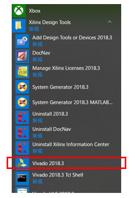
Vivadoのインストールと設定
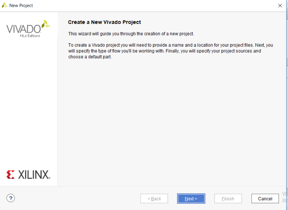
まずは、Vivadoの起動から。
Example Projectを元に、作って行く方法もありそうだが、参考記事のとおり、私も「RTL Project」を選ぶ。
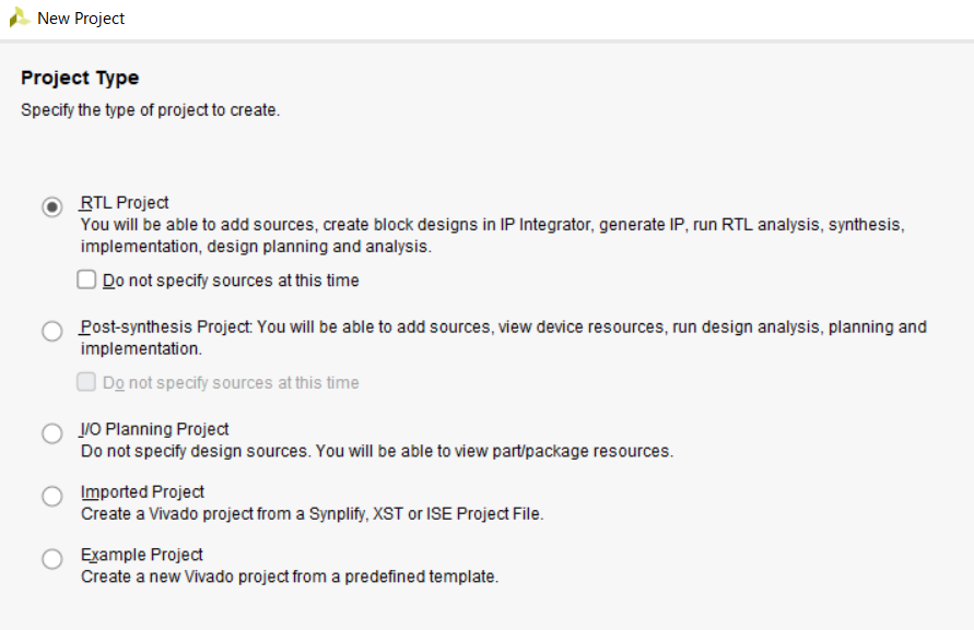
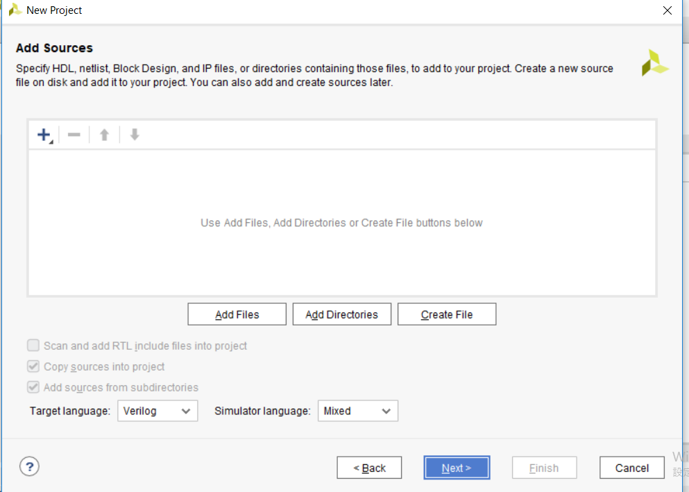
ソースは未だ何も作っていないので、Nextで次へ。
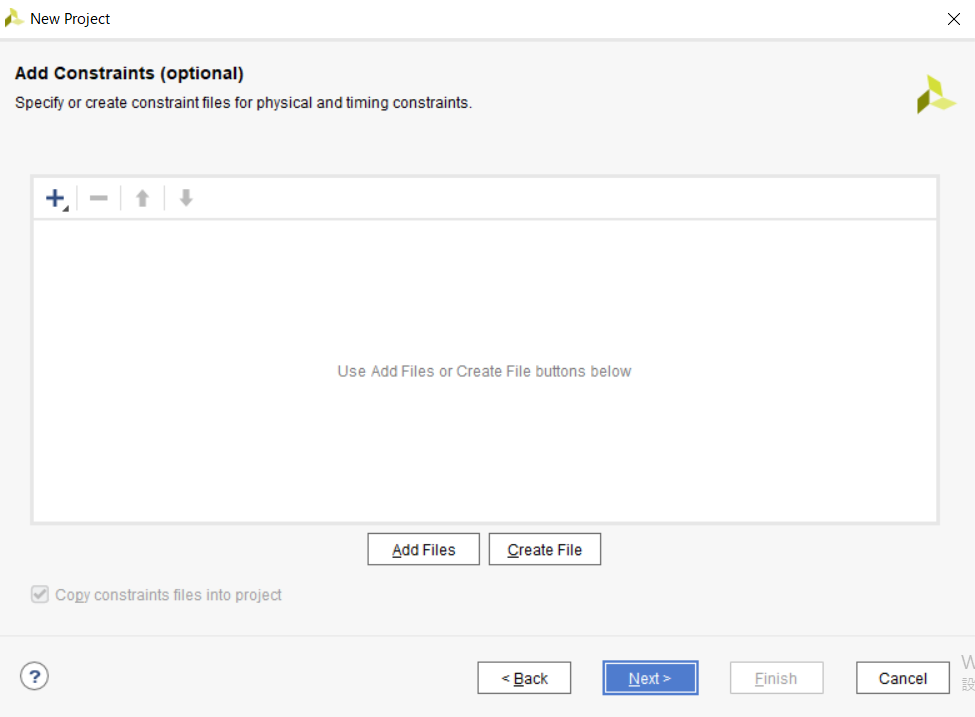
Constarintsでは、PYNQボードの設定ファイルを指定するらしい。「Add Files」から、*.xdcというファイルを選ぶらしい。こちらの記事
を参考に設定していきます。記事には以下のような説明があるので、PYNQの場合も、PYNQ Board definition fileと、PYNQ XDC fileというが必要そうだということは分かった。
DigilentのZYBOのサイトへ行きます。
http://www.digilentinc.com/Products/Detail.cfm?NavPath=2,400,1198&Prod=ZYBO
ここにはZYBOの回路図などもあるので後々役に立つかもしれません。
今回はVivado用の2つのファイルをダウンロードします

ZYBO Board Definition File for configuring the Zynq Processing System core in Xilinx Platform Studio and Vivado IP Integrator.
ZYBO Master XDC File for Vivado designs.
Boardの設定ファイルの設定
色々調べた結果、PYNQ-Z1の場合は、
https://pynq.readthedocs.io/en/v2.3/overlay_design_methodology/board_settings.html
このページから、 PYNQ-Z1 board files , PYNQ-Z1 master xdc constraintsという2つのファイルを落とすことが判明。
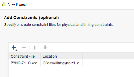
以下2つのファイルを落としますが、どうもPYNQ-Z1_C.zipの方だけでいいみたい。解凍するとPYNQ-Z1_C.xdcというのが現れる。
pynq-z1_c.zip
pynq-z1.zip
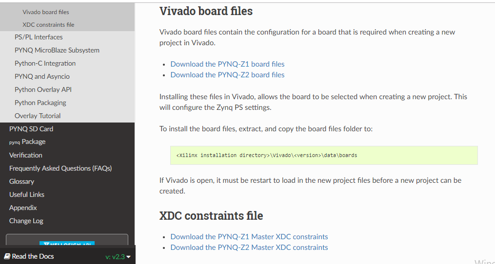
ダウンロードした2つのうちpynq-z1_c.xdcというのを選択します。
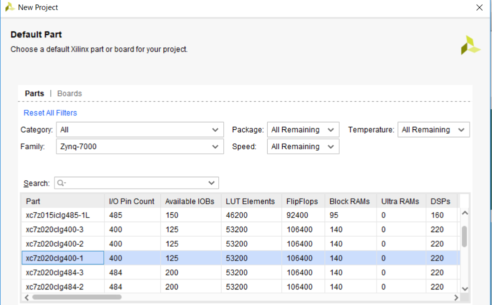
で、「Default part」ダイアログが重要みたい。
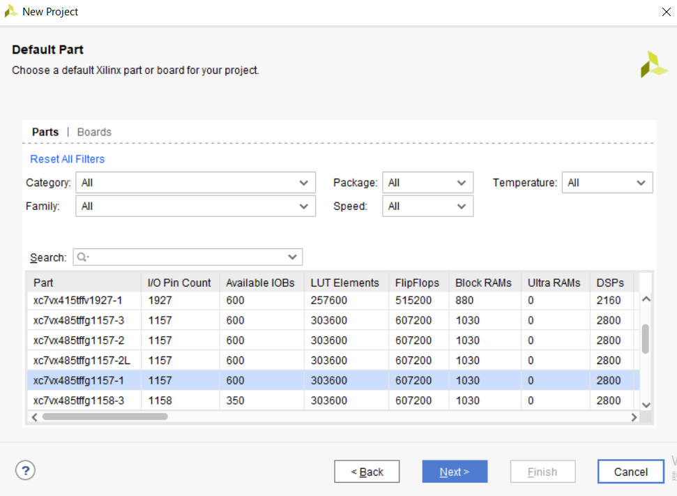
まず、partってなんぞや?
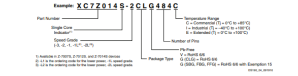
XC7Z020-1CLG400C
というのが、PYNQ-Z1のチップ名のようです。デバイス名の命名則は以下の資料は、
https://japan.xilinx.com/support/documentation/data_sheets/j_ds190-Zynq-7000-Overview.pdf
のP.21に説明があります。
なので、
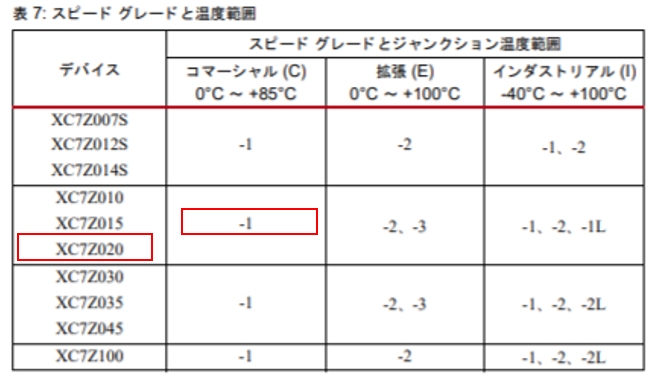
最後の桁が、1か2か3か?悩んだのですが、チップ名の最後がCなので、
C列で且つ、xc7z020で当てはまるのは、-1ということで下図のように選択しました。どうか、これで合っていて欲しい。
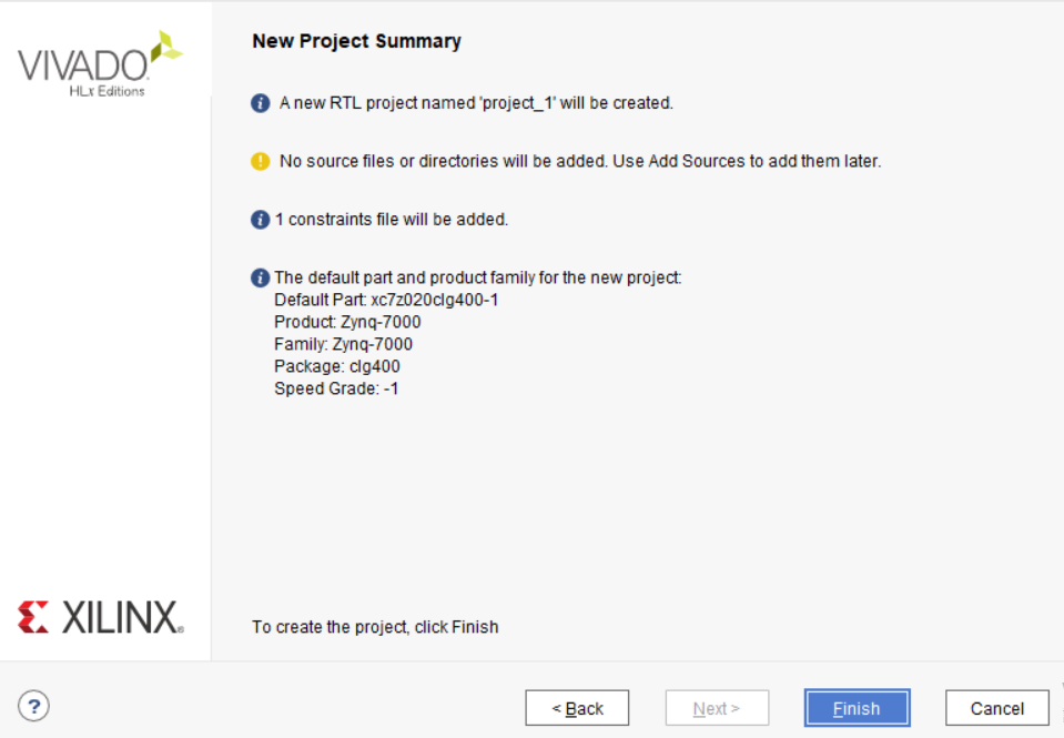
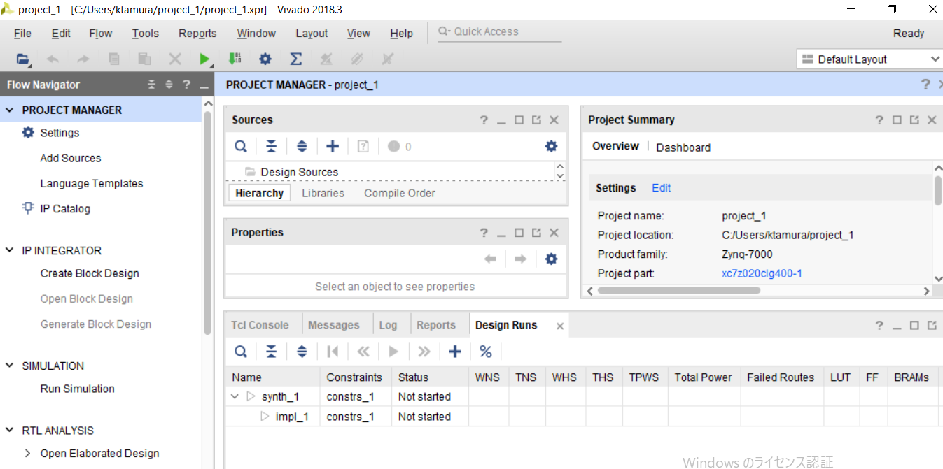
すると、おお!プロジェクト画面が出てきました。
ここまでのVivadoのインストール手順は、こちらの記事を参考に、PYNQ-Z1用に調査してみた次第です。
VivadoでHelloWorldを動かしてみよう
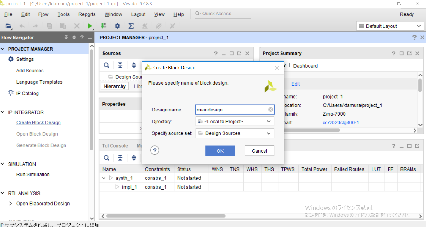
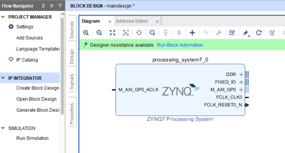
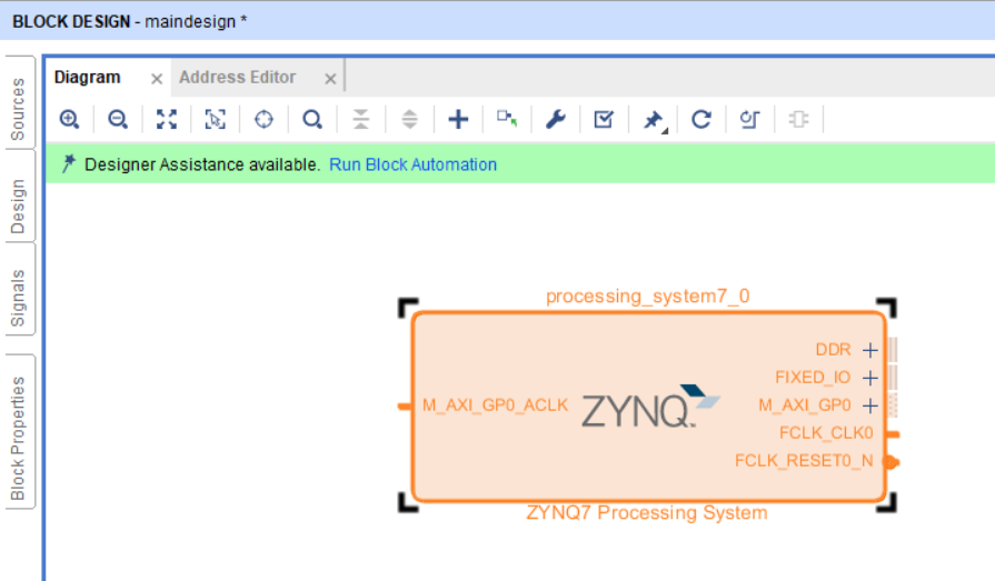
+のアイコンを押すと、IP(Intellectual Property)を追加するダイアログが出てきます。検索でzynqと入れると
[ZYNQ7 Processing System]というのが出てくるので、選択。

Block Diagramウィンドウの中に、
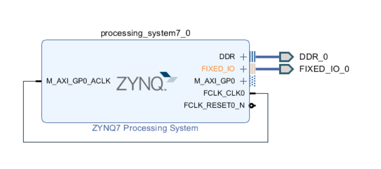
Generate Block Design