はじめに
経緯
インターネット黎明期のある会合
インターネット黎明期の1994年10月、JAIN コンソーシアム@志賀島(JAINコンソーシアム)という会議において、インターネットをこれからどう使うか?という議論がありました。ちょうどこの頃、インターネットでピザの宅配が実現されていたので、うどんの宅配の注文をオンラインで行おうという意見が出ました。これを聞いて、私は、うどんをインターネットで配送しようと言ってしまいました。言ってしまっては責任を取らなければなりません。
What How For 北九州(北九州テクノサロン)
北九州市の活性化のために何か面白いことをしようという会議、What How For 北九州、が開催されていて、私も参加させてもらっていました。1995年、テレポーテーションしたい、とJAINコンソーシアムで言ってしまったので、実現できないか?と提案してみました。面白がってもらって、やってみようかということになりました。その会議の関係者である強力な共同研究者も一緒に活動することになりました。
現実的なテレポーテーションシステム実現プロジェクト:テスラ計画
What How For 北九州の主査(座長)の先生が、ニコラ・テスラがテレポーテーションを研究していた、という噂があるので、テスラ計画、と名付けよう、と提案されました。ニコラ・テスラのテレポーテーションについては、それ以前の映画「フィラデルフィア・エクスペアリメント」や、その後の映画「プレステージ」で上映されました。テスラ計画では、いろいろな方法を模索し、相補的な結合システムによる部品間の接続と、相補的な配置を使った部品間通信方式を発明し、特許を取得しました。
- 山之上卓, 筒井保博, 筒井隆夫, 特許第4373556号,"セル及びその結合状態認識方法", 9/11, 2009.
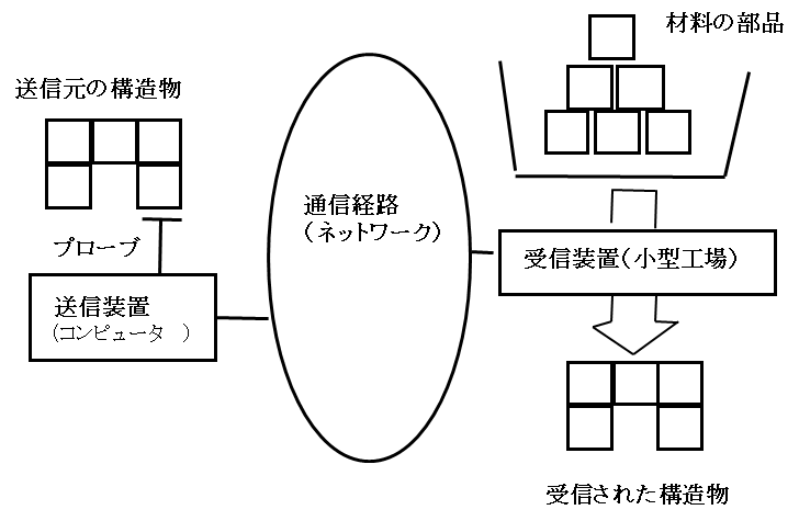
テスラ計画のテレポーテーションの概要
テスラ計画のテレポーテーションは、以下のようにして実現する、機能を持った「物」を遠隔地に転送する、一種の FAX/TV です。
- 送信する「物」は知的な部品「テスラダイス」を組み合わせて作成されているものとします。
- 「物」は、その部品同士で通信を行い、自分自身の物理的構造と機能の情報を把握できるようにします。
- 把握された情報を外部に抽出し、インターネット等の通信手段で遠隔地に送信します。
- 遠隔地でその情報を受信し、その場(遠隔地)にあるテスラダイス(部品)を材料として、その場にある「受信装置(小型工場)」で、受信した情報を元に、送信された「物」と同じものを作成します。
- 必要に応じて、送信元の「物」を消します。
システム概要
システム概要について簡単に述べますが、詳しくは以下の参考文献などをご覧ください。
- 山之上 卓, "テレポーテーションとコンパイラ", 情報処理学会夏のプログラミングシンポジウム 2004, pp.99-102, 函館, 22-24 Aug. Japan, 2004.
- Takashi Yamanoue. Yasuhiro Tsutsui, Takao Tsutsui, "Realizing a Practical Teleportation System Using the Intelligent Parts," Proceedings of the 1st International Conference on Information Technology and Applications (ICITA-2002),221-2, Bathurst, Australia, Nov. 25-29, 2002.
テスラダイス、その結合方法と通信方法
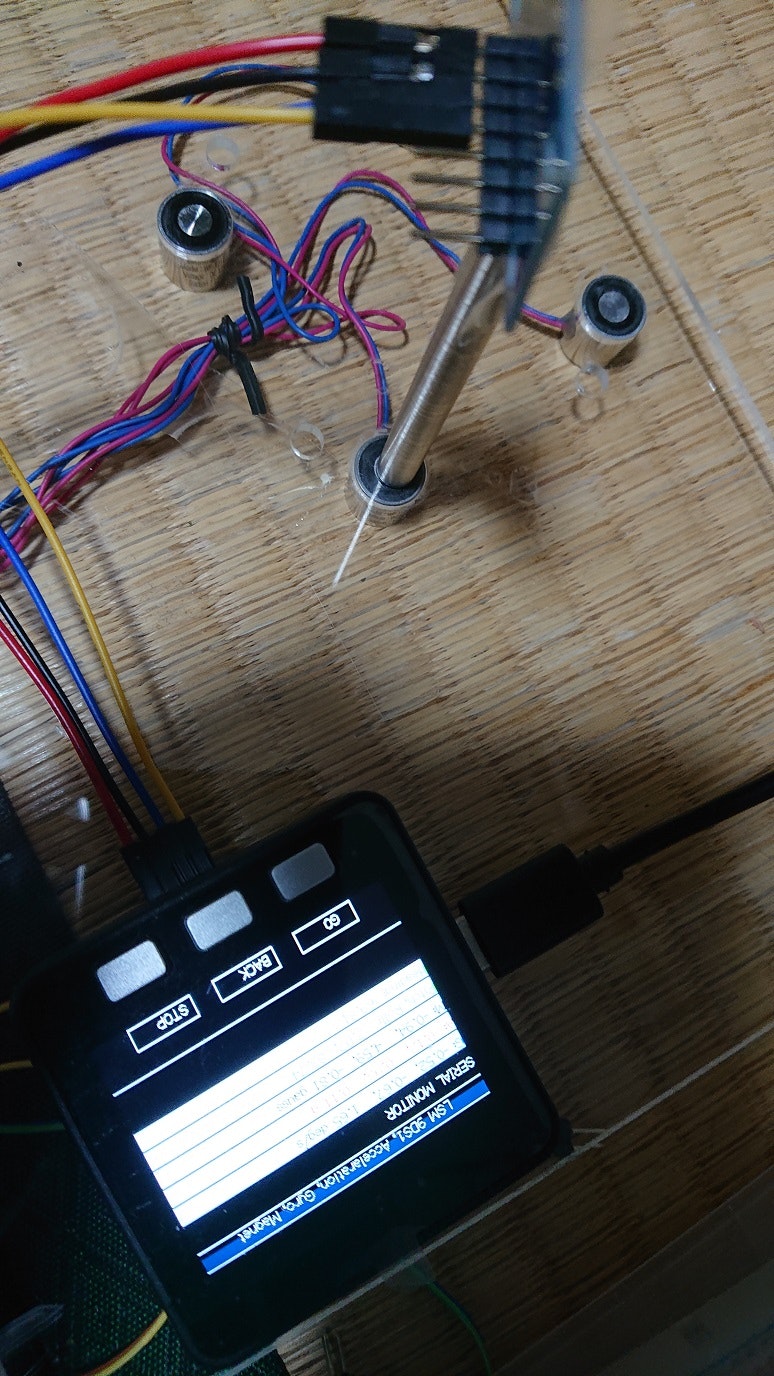
送受信される「物」を構成する部品である、テスラダイスは、その面に、磁石などの結合装置を結合面に相補的に配置しています。このことにより、双方に結合装置がついた面が重なる向きであれば、2つのテスラダイスは、どの向きでも結合できます。また、相補的で非対称性のある送受信素子を面に配置することにより、テスラダイスは、面と面が重なる向きであれば、どの向きでも部品間で相互に、全二重の通信が可能になると同時に、面の結合の向きも知ることができます。とりあえず、テスラダイスの形は正六面体のものをまず実現してみることにしました。
部品間通信と構文解析手法を用いた「物」の構造の把握
どの部品とどの部品が、どの面で、どの向きで結合しているか、または結合していないか、転送される物の全ての部品の全ての面について情報を得ることによって、この物の物理的な構造を再現することができます。この情報を得るために、物理的な物の「構文解析」を行い、その結果の情報を「属性文法」を使って吸い上げることにより、入手することができます。
受信装置
被送信物の情報を上の方法で入手し、これをインターネットなどの手法で遠隔地に送り、この情報を自動工場で構成される受信装置に入れることにより、元の「物」を再生することができます。世の中にはすでに、3次元プリンタやマシニングセンタがありますので、これらを使えば、受信装置はできるはずです。
シミュレータ
以上の概要のべたテレポーテーションシステムが実現可能であることを示すため、シミュレータを作成しました(少なくとも、2002年にはこのシミュレータは実現していました... The 1st International Conference on Information Technology and Applications (ICITA-2002),221-2, Bathurst, Australia, Nov. 25-29, 2002.)。
進捗状況
知的な部品:テスラダイス
mbed LPC1768とphoto transister, LEDなどを組み合わせて、最低限の機能を実装しました。
自分自身の物理的構造の情報把握
上で述べたシミュレータの機能をテスラダイスのmbed LPC1768のプログラムに入れることにより、物理的構造の情報把握を実現しました。
(機能情報の把握はこれからだけど、コピーするだけなので、すぐにできるはず)
Real->Virtual の実現
以上のテスラダイスとそのプログラムを使って、2021年度に、「物」の情報を取り出し、その情報を使って、仮想空間上で、「物」を再現することに成功しました。
以下で発表しています。
- 山之上 卓,筒井 保博,筒井 隆夫,
"Real から Virtual への移動システムの実現の試み:Real から Virtual への移動システムの実現の試み",
情報処理学会インタラクション2022論文集3D-20, 2022年3月1日. - 山之上 卓, 「Real -> Virtual 変換システムの開発その1の1」 IoTLT, vol.80, 2021年10月21日.
- yamnoue,「Real -> Virtual 変換システムの開発その1」 Protp Pedia.
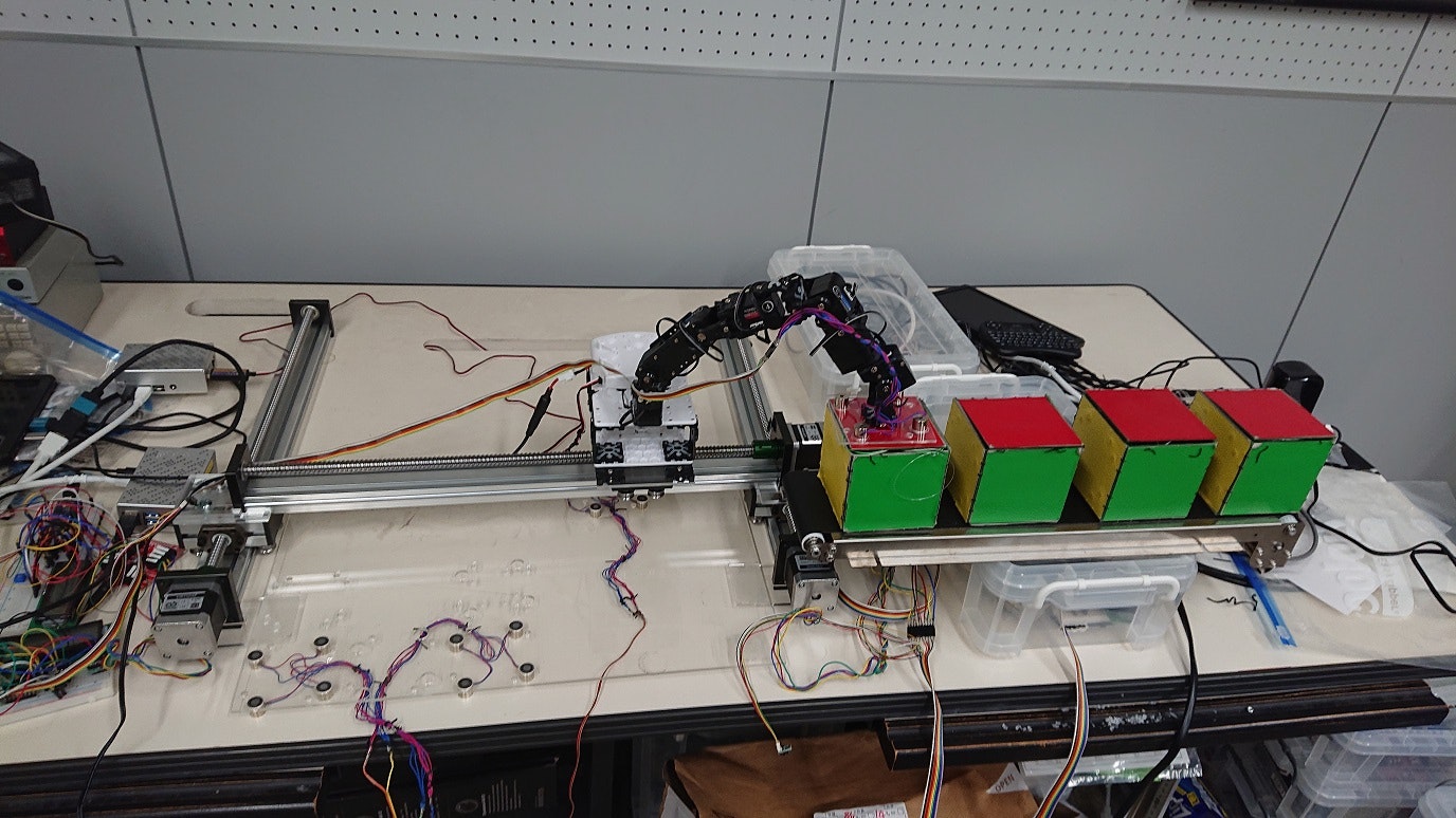
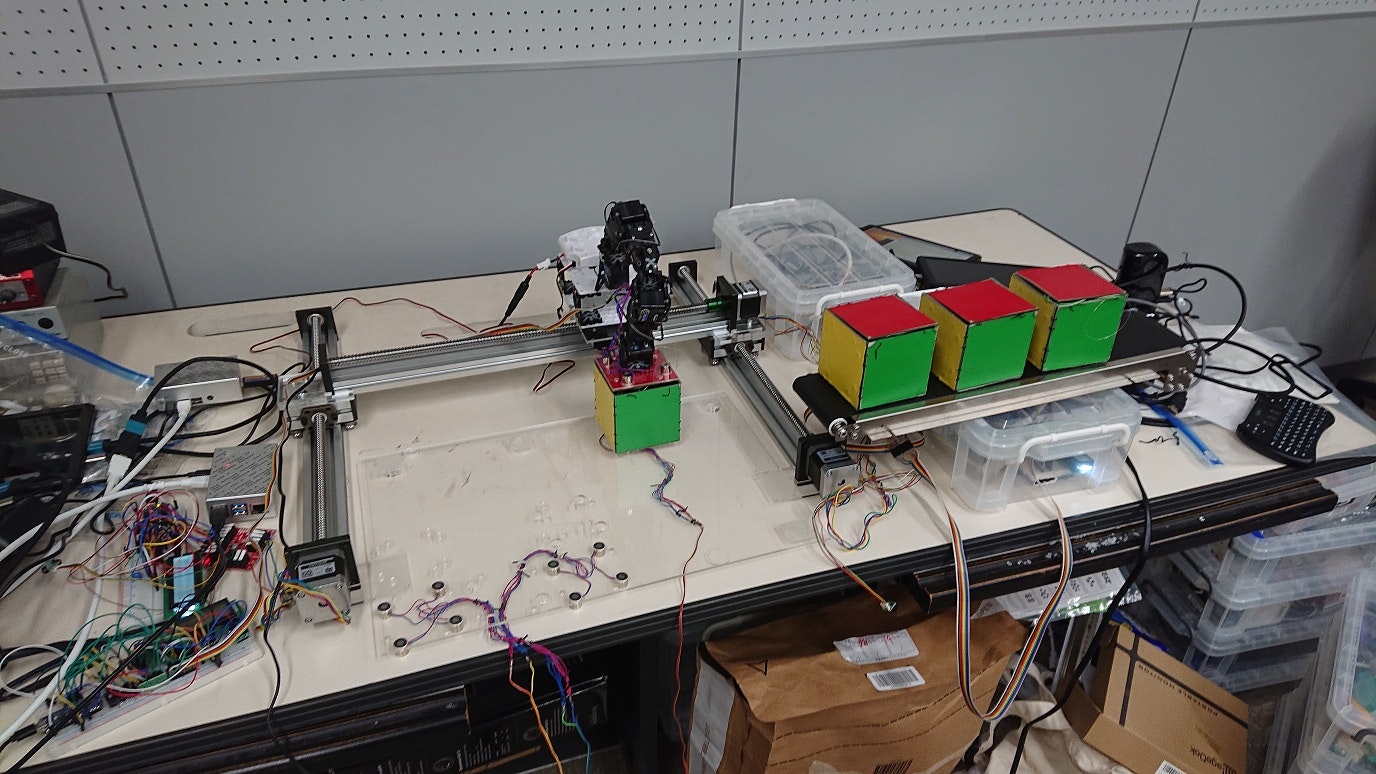
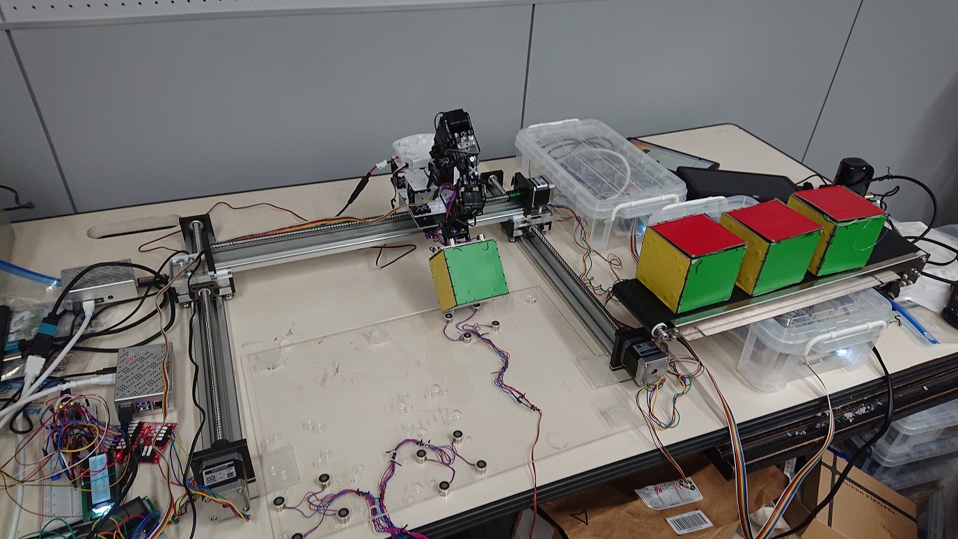
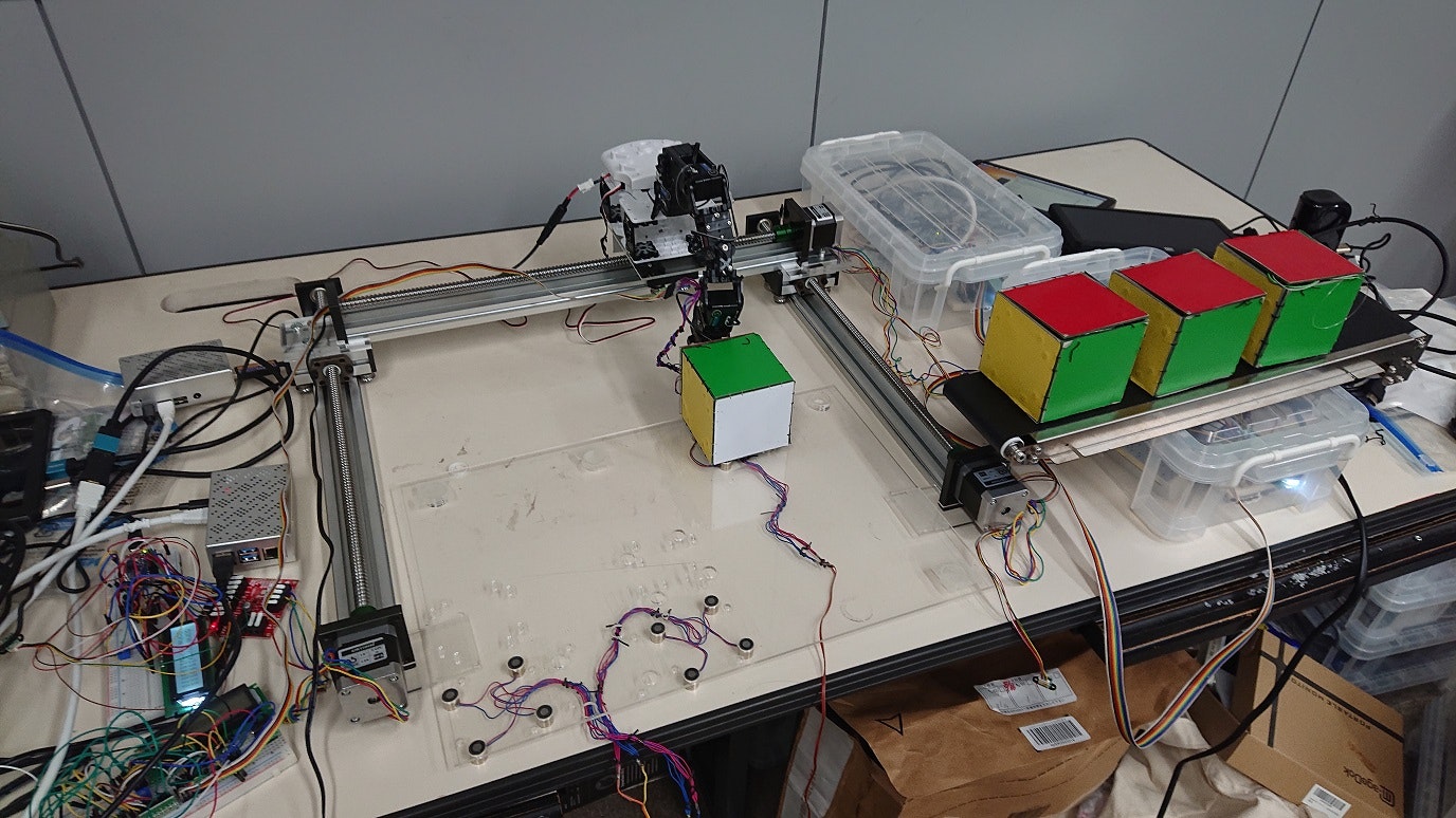
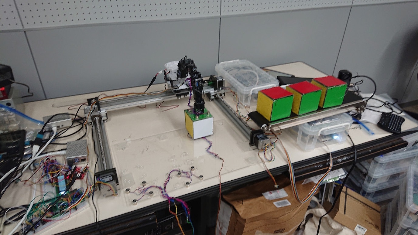
受信装置
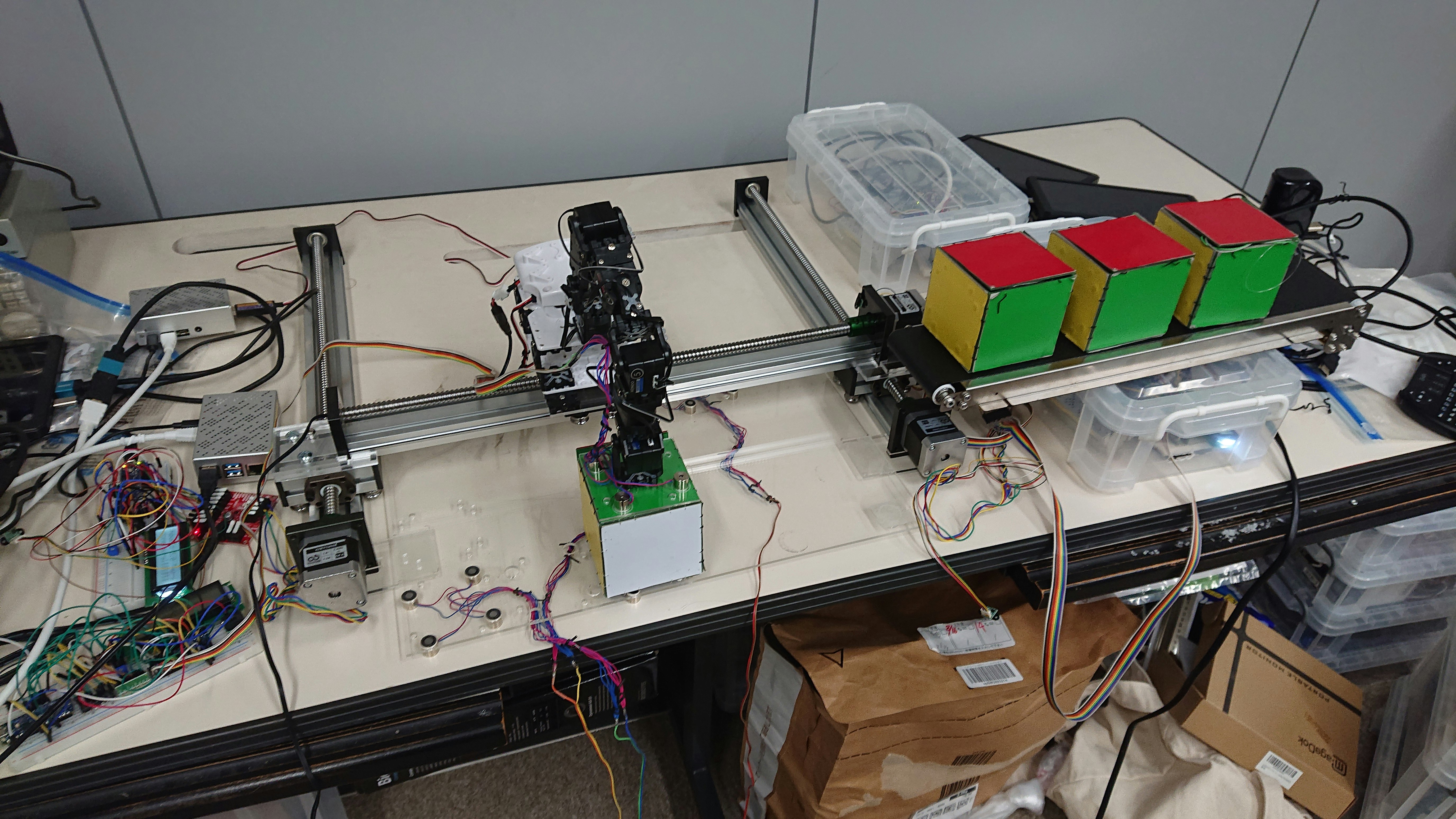
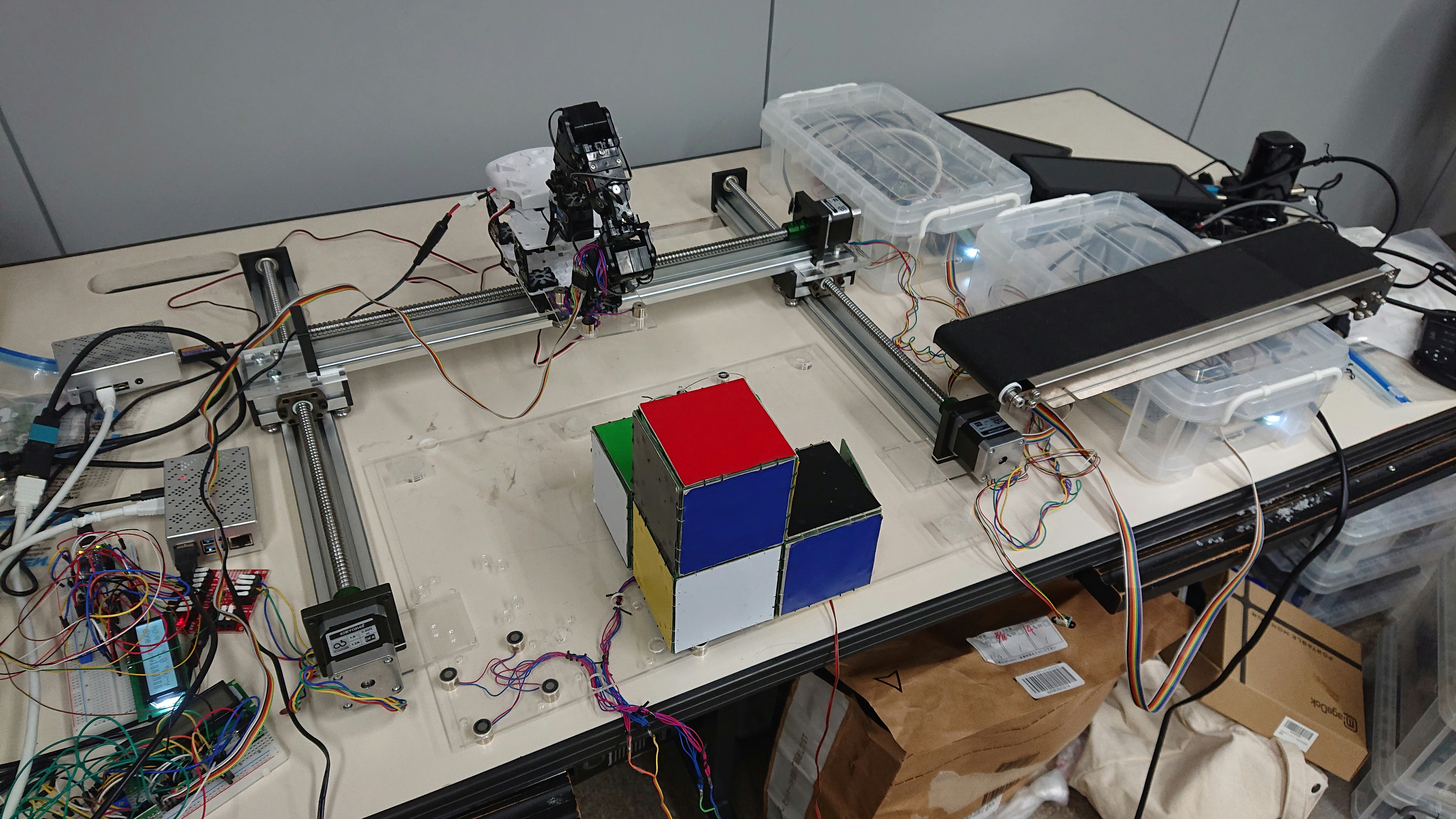
現在、受信装置を作成中です。当初、fischertechnikを使って、受信装置を作成しようとしていたのですが、なかなかうまくいかないので、ステップモータ駆動のリニアスライドテーブル、アームロボット、ベルトコンベアなどを組み合わせて実現しようとしています。
以下、こうなる予定を示します。
被転送物が上の写真のような物だったとします。この物の構造情報を、先に述べた方法を使って、物が自分自身で入手し、外部に取り出します。

受信装置がその構造情報を受け取り、物の再生(組み立て)を開始します。
まず、アームロボットがベルトコンベアからテスラダイスを一つ取り出します。
この時、テスラダイスの把握のため、電磁石を使います。
アームロボットはそのテスラダイスを、組み立てテーブルの、部品回転用の電磁石が付いた床の部分に移動させます。テスラダイスが一つなくなったベルトコンベアは、そのことを検知し、所定の位置に次のテスラダイスが来るようにベルトを動かします。
アームロボットの電磁石と、床の電磁石と、アームロボットとスライドテーブルを操作して、テスラダイスの向きを水平方向に回転させたり、垂直方向に回転させたりします。
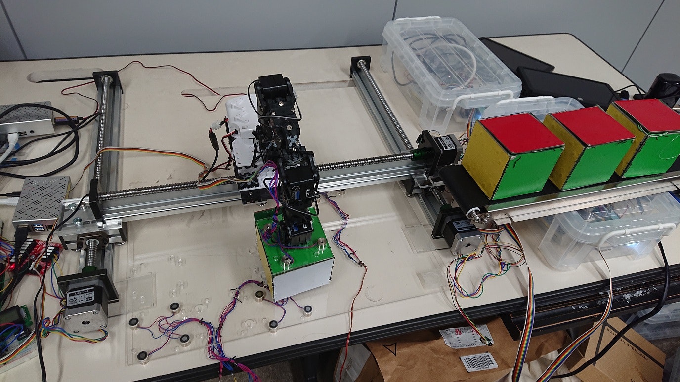
方向が定まったテスラダイスを、それがあるべき場所に、スライドテーブルとアームロボットを使って移動させます。
最初の一個は、床に電磁石がついている場所に置かれ、その電磁石で固定されるものとします。
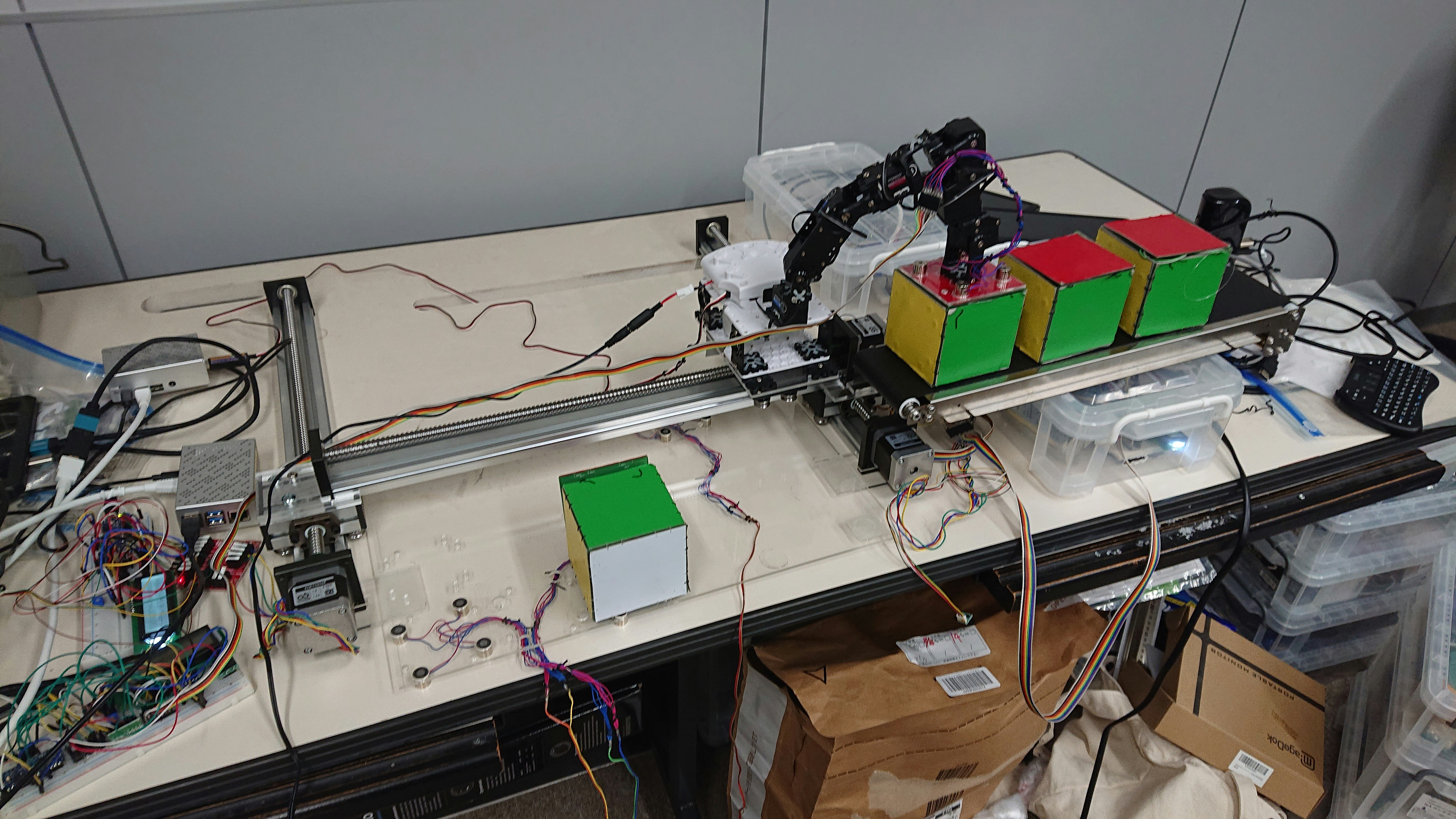
ロボットアームが移動し、次のテスラダイスを取り出します。
以上を繰り返し、被転送物と同じものを作成します。
部品の並行移動
ステップモータ駆動のリニアスライドテーブルを3本使って、 X-Y 方向の部品移動を実現します。Z方向については、ロボットアームを使うつもりです。
部品の回転
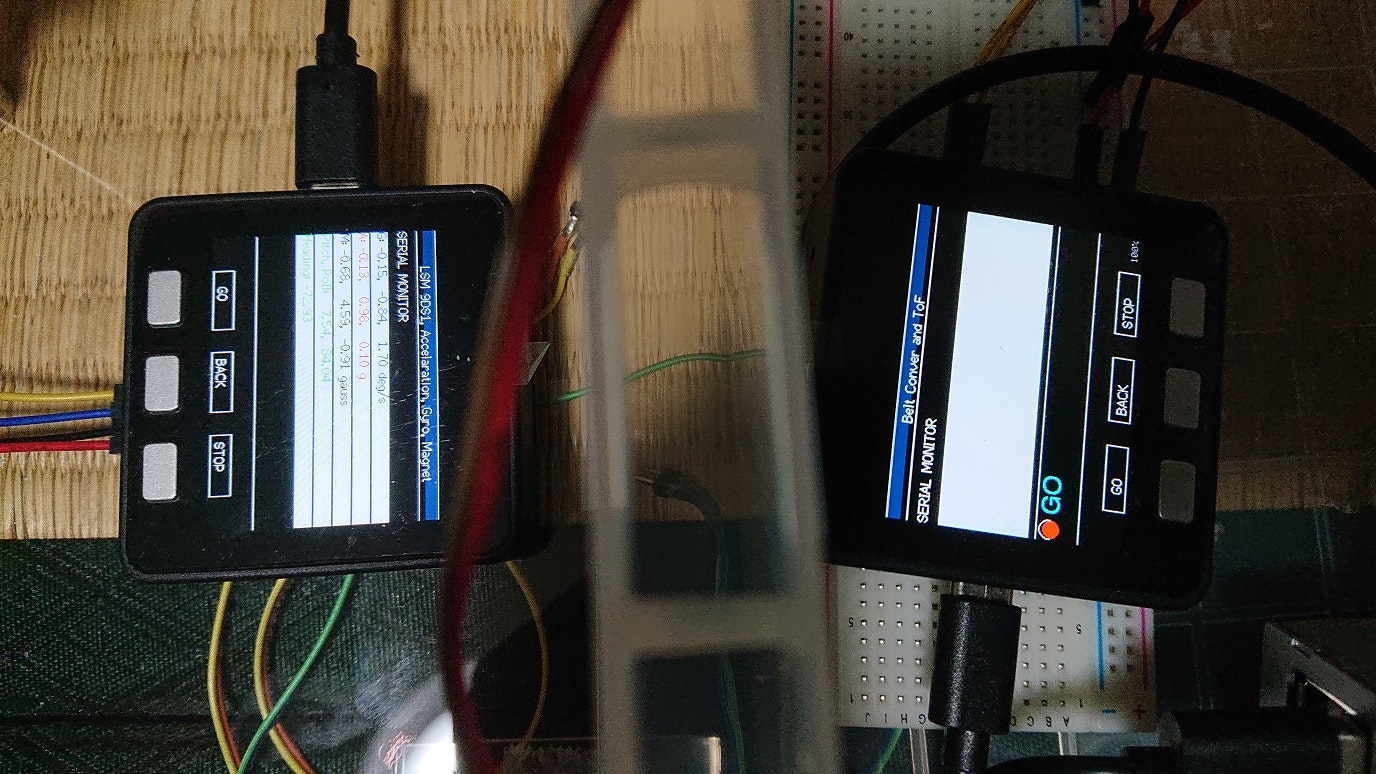
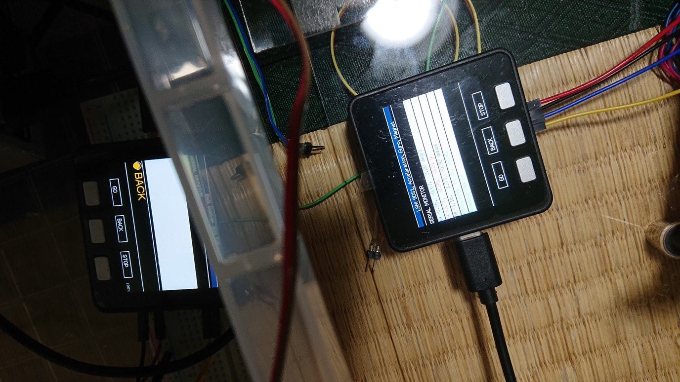
部品の回転は、上で述べたように、ロボットアームと電磁石とスライドテーブルを使って実現するつもりです。これらの制御のために、Step Motor Driver, Motor Driver (H-bridge), TOFセンサ, Arduino, M5Stack, Raspberry Pi などを使います。
部品供給用ベルトコンベア
部品供給用ベルトコンベアは、DCモータ駆動の安価なものを使っています。自動的にベルトを動かすために、TOFセンサを使っています。
ソフトウェア
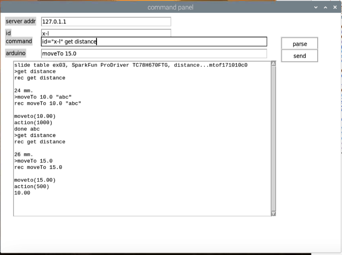
Arduino nano every と Step Motor Driver を使って、リニアスライドテーブルを制御しています。移動限界検知のため、TOFセンサを利用する予定だったのですが、どうも精度が出ないので、考え直さないといけないかもしれません。
全体を制御するための、「main controller」 プログラムを1台のRaspberry Piで動作させます。「物」の情報からテスラダイスを使った物の組み立て方を自動的に計算させ、その結果を用いて、main controller がリニアスライドテーブル、ロボットアーム、電磁石に付いた Raspberry Piの「中継プログラム」にコマンドを送り、中継プログラムが Raspberry Pi にUSBケーブルで接続されたArduinoやM5Stackにコマンドを送り、それぞれの動作を行います。
本題...秋月AE-TB67H450とM5Stack(Basic)とRaspberry Piを使った電磁石の制御
電磁石を使ったテスラダイスの把握と分離
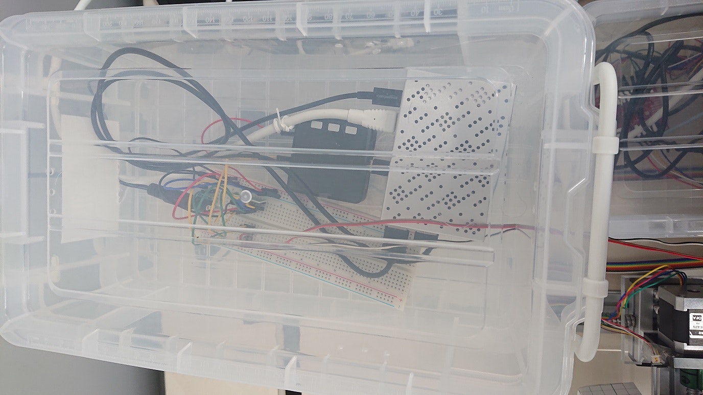
ベルトコンベアからテスラダイスを取り出したり、持っているテスラダイスをスライドテーブルで移動した後、その場所に置いたりするために、受信装置のアームロボットの、部品の把握・分離機構が必要になります。置いたテスラダイスを固定したり、テスラダイスを回転させたりするためにも、テスラダイスをアームロボットが掴んだり、離したりしなければなりません。部品を床に固定したり、離したりする必要もあります。機械的に掴んだり離したりしても良いのですが、機構が難しそうです。そこで、上の例で示した通り、電磁石を使って実現してみようとしています。
ハードウェア
電磁石に電流を流すため、秋月のAE-TB67H450を使うことにしました。これによって、順方向に電流を流してテスラダイスを吸着し、逆方向に電流を流して、テスラダイスを分離できるはずです(後で、これが一筋縄ではいかないことがわかりました)。AE-TB67H450 を駆動するために、M5Stack Basic を使うことにしました。M5Stackのボタンを使って、直接、電流を順方向に流したり、逆方向に流したり、電流を止めたりすることを可能にし、Raspberry Pi から送られてくるコマンドに従って、同じ操作を行ったり、今、どのコマンドを実行しているか、表示したりすることを可能にしています。
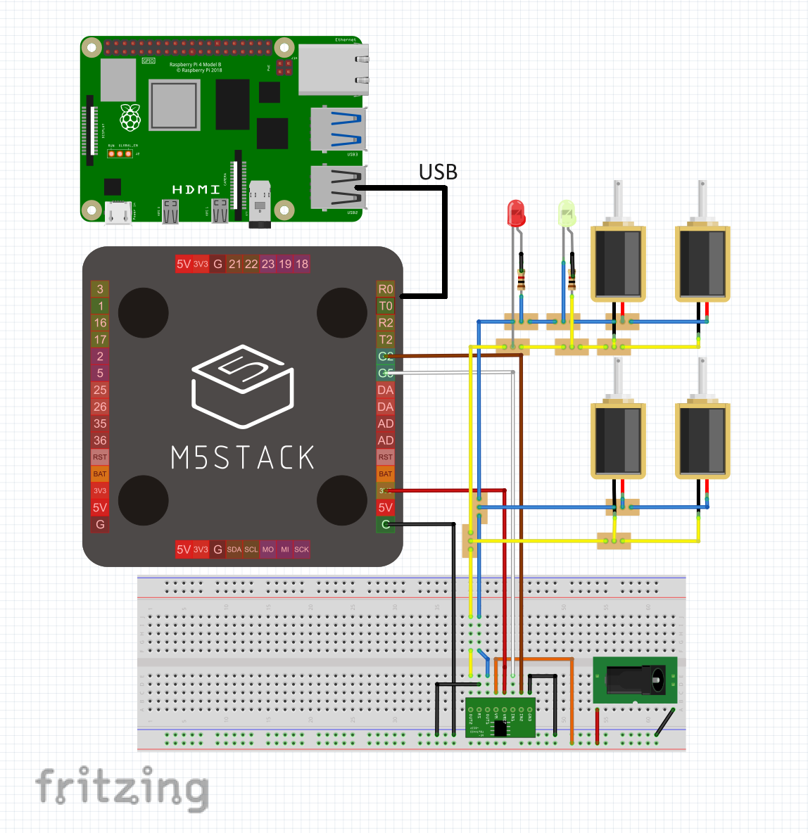
(この図の作成にあたり、fritzingのM5Stackの部品は、https://github.com/lukasmaximus89/M5Stack-Fritzing/tree/master
にあるものを使わせていただきました。AE-TB67H450の部品は、https://github.com/ohguma/Fritzing-Parts/tree/master にあるものを使わせていただきました。両ページの作成者に感謝します。)
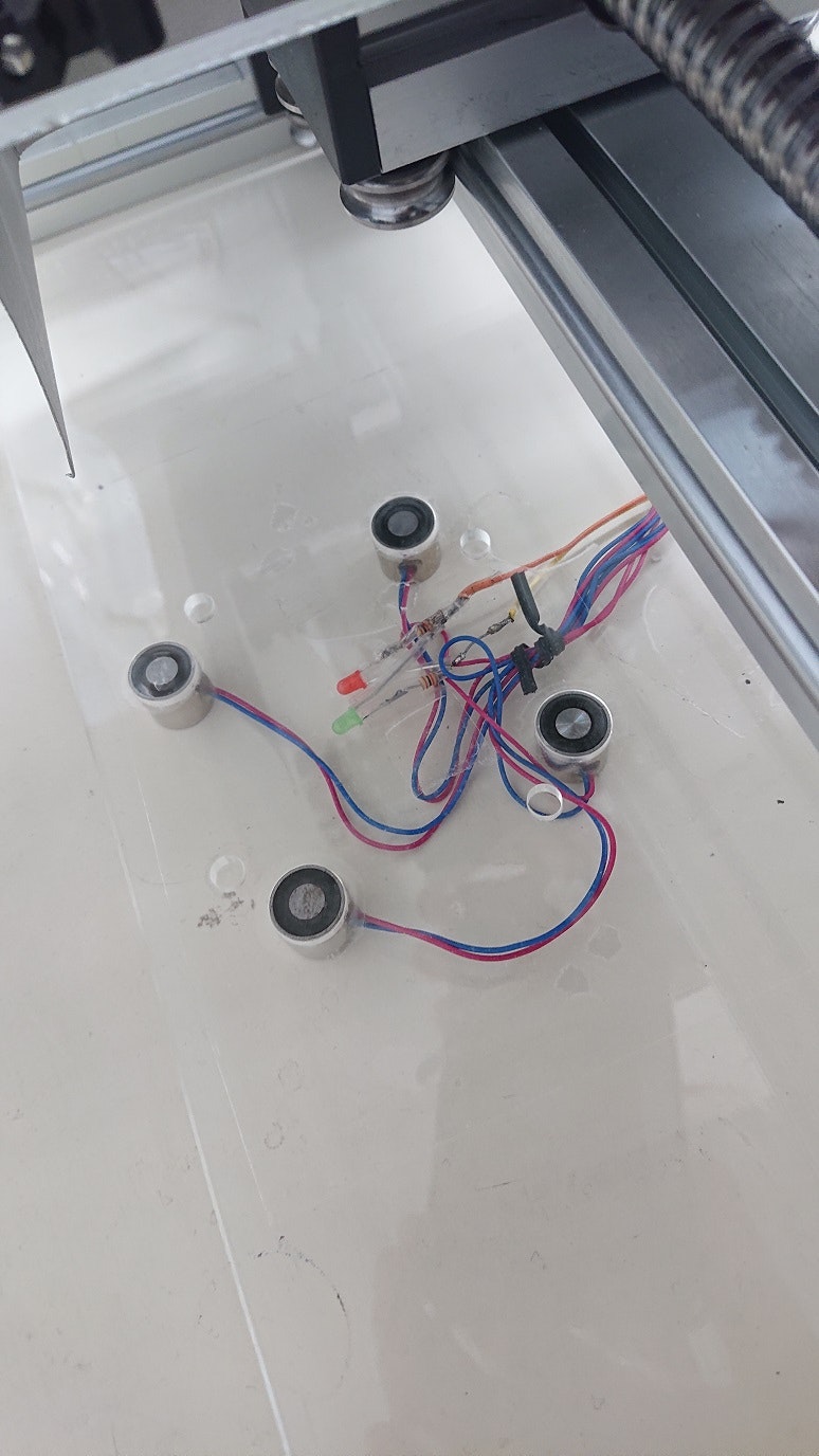
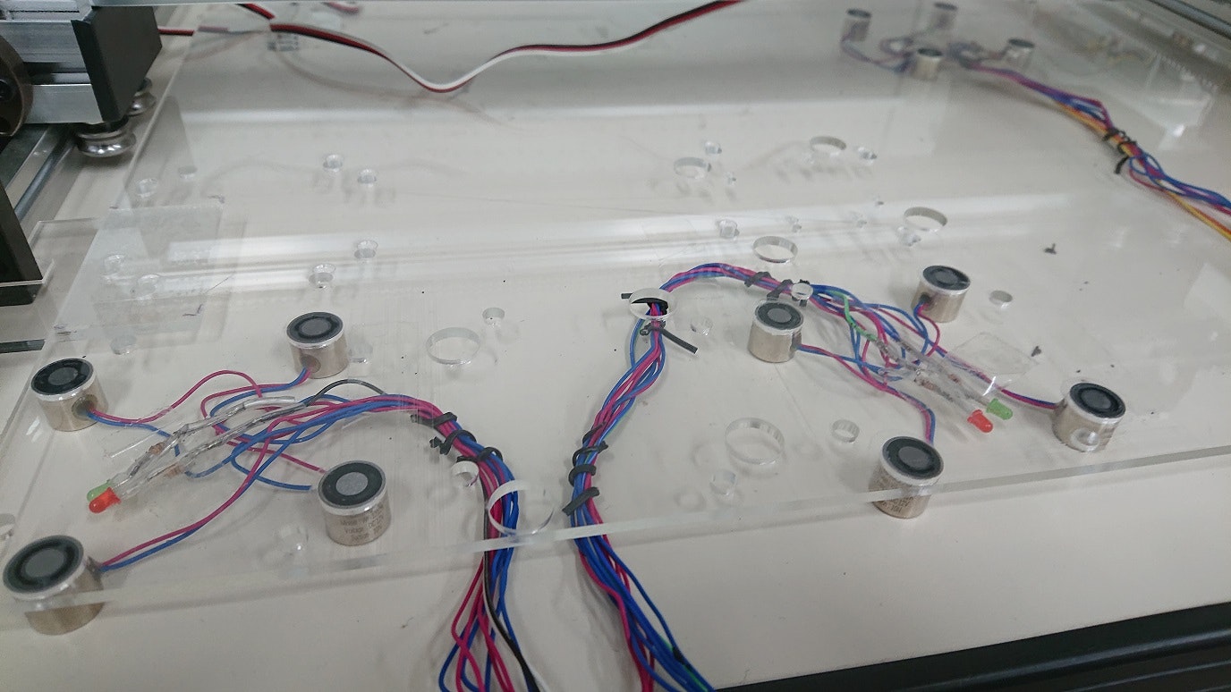
それぞれの把握・分離機構は4つの電磁磁石を並列に繋いで、これにAE-TB67H450を通じて、12Vの電源から電流を流しています。4つの電磁磁石を
並列に繋いだ時の抵抗は6Ω強ありました。これに12Vの電圧をかけるのでI=E/R=12V/6Ω=2Aとなります。TB67H450は、出力耐圧 50 V、最大電流(3.5A)
と、データシートに書いてありますので、12V2Aは許容範囲内に収まっています。
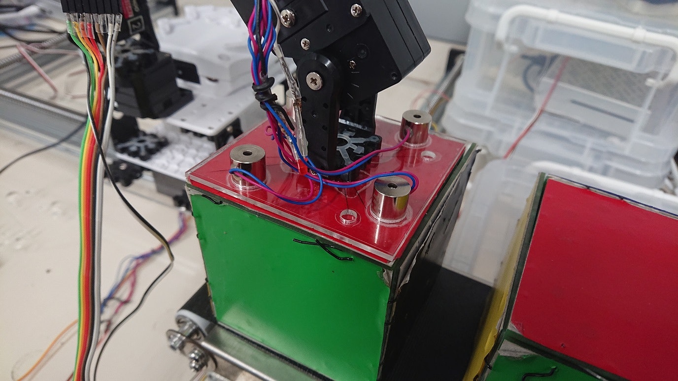
ロボットアームに取り付た電磁石把握・分離機構が、部品供給ベルトコンベアに載ったテスラダイスを掴んでいるところ。
ロボットアームに取り付た電磁石把握・分離機構の吸着面。
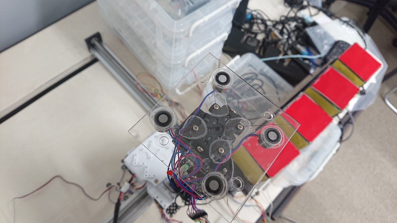
テスラダイスの向きを変えるための、床の電磁石把握・分離機構
作成中の「物」を一時的に固定するための、床の電磁石把握・分離機構
1つの電磁石把握・分離機構の制御部を入れた箱。
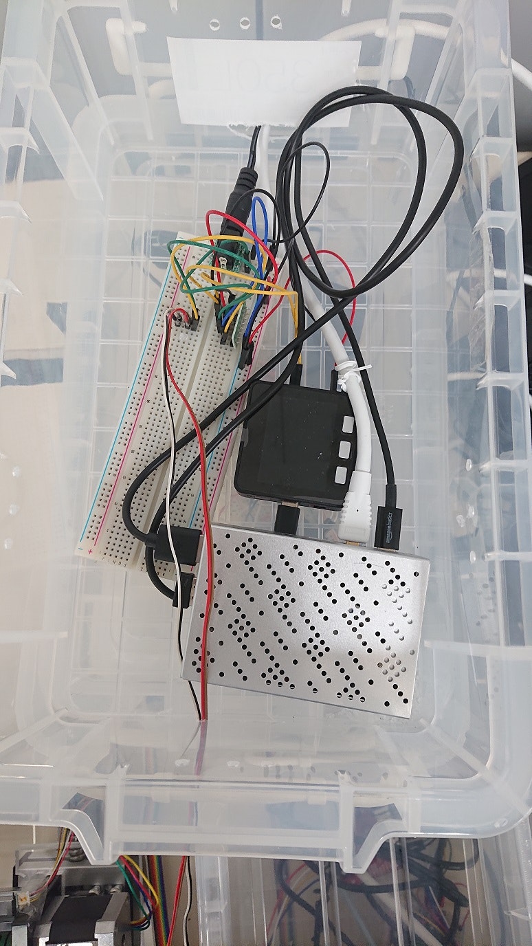
箱のふたを開けたところ。Raspberry Pi, M5Stack Basic, AE-TB67H450 などが入っています。
ソフトウェア
M5Stack のプログラム
(このサイトのプログラムを利用させていただきました: https://logikara.blog/m5stack-basic/ 感謝します。)
#include <M5Stack.h>
/*
M5Stack Basic V2.6端子仕様
G3/G1 :UART0通信用(RX/TX) ※標準のシリアル通信未使用なら入力/出力使用可、書き込み時は未接続にする
G16/G17:UART2通信用(RX/TX) ※シリアル通信2未使用ならG16は入力/出力、G17は出力のみ使用可
G2/G5 :入力/出力/G2のみアナログ入力可
G25/G26:G25はスピーカー専用、G26は入力/出力/アナログ入力/アナログ出力
G35/G36:アナログ入力(入力としても使用できるがプルアップ不可)
G21/G22:I2C通信用 Groveコネクタと共通(SDA/SCL) ※入出力使用可だが電源ICと繋がっているため非推奨
G23/G19/G18:SPI通信用(MOSI/MISO/SCK) ※G19のみ入出力使用可だがTF(SD)Cardと繋がっているため非推奨
G39/G38/G37:本体ボタン(左からボタンA,B,C、内部で接続)
*/
// 端子割り付け
#define HB1 2 // H bridge 1, 出力
#define HB2 5 // H bridge 2, 出力
//#define ADC0 35 // アナログ入力端子
//#define DAC0 26 // アナログ出力端子
// constant
#define ADDRESS 0x52
#define MESSAGE_MAX 5
// 変数宣言
//float ad_val; // アナログ入力値格納用
//float da_val; // アナログ出力値指定用
//float v_in = 0; // アナログ入力電圧換算値
//float v_out = 0; // アナログ出力電圧換算用
int cnt = 0; // 表示回数カウント用
String data = ""; // シリアル通信の受信データ格納用
String goState ="STOP";
String lines[MESSAGE_MAX];
String inputString;
uint16_t distance; //tof
uint16_t distance_tmp; //tof
uint8_t data_cnt; //tof
uint8_t message_line; //
// 関数 ************************************************************************
// シリアルモニタ出力処理
void return_result(String data) {
for(int i=0;i<MESSAGE_MAX-1;i++){
lines[i]=lines[i+1];
}
lines[MESSAGE_MAX-1]=data;
M5.Lcd.fillRect(205, 52, 115, 18, WHITE);
M5.Lcd.setTextFont(2); // フォント
M5.Lcd.setCursor(210, 53); M5.Lcd.setTextColor(BLACK); // 座標指定(x, y) // 文字色、背景
M5.Lcd.fillRect(0, 52, 320, MESSAGE_MAX*18, WHITE); // 塗りつぶし四角
for(int i=0;i<MESSAGE_MAX;i++){
M5.Lcd.setCursor(0,50+i*18);
M5.Lcd.print(lines[i]); // 受信データ液晶表示
}
Serial.println(data); // 受信データ標準シリアル出力
}
// 初期設定 ************************************************************************
void setup(){
M5.begin(); // 本体初期化(LCD, SD, Serial, I2C)
M5.Power.begin(); // 電源初期化
Serial.begin(115200); // 標準のシリアル通信初期化(初期値はG3(RX),G1(TX))
//Serial2.begin(9600); // シリアル通信2初期化 (初期値は G16(RX), G17(TX))
// 入出力ピン設定
// 出力設定
pinMode(HB1, OUTPUT); // to H bridge control output
pinMode(HB2, OUTPUT); // to H bridge control output
digitalWrite(HB1, LOW); //
digitalWrite(HB2, LOW); // set stop
goState="STOP";
//LCD表示
M5.Lcd.fillScreen(BLACK); // 背景色
M5.Lcd.setTextSize(1); // 文字サイズ(整数倍率)
M5.Lcd.setTextFont(2); // フォント 1(8px), 2(16px), 4(26px)
// 6(36px数字-.:apm), 7(7セグ-.:), 8(75px数字-.:
M5.Lcd.drawFastHLine(0, 0, 320, WHITE); // 指定座標から平行線
M5.Lcd.fillRect(0, 1, 320, 13, (uint16_t)0x098a); // タイトルエリア背景
M5.Lcd.drawFastHLine(0, 20, 320, WHITE); // 指定座標から平行線
M5.Lcd.setTextColor(WHITE); // 文字色
M5.Lcd.drawCentreString("Belt Conver and ToF", 160, 4, 2); // 指定座標を中心に文字表示(x, y, font)
// M5.Lcd.drawFastVLine(0, 29, 320, WHITE); // 指定座標から垂直線(x, y, l, 色)
M5.Lcd.drawFastHLine(0, 149, 320, WHITE); // 指定座標から平行線(x, y, l, 色)
// M5.Lcd.drawFastHLine(0, 132, 320, WHITE);
M5.Lcd.drawFastHLine(0, 192, 320, WHITE);
M5.Lcd.drawCircle(10, 161, 9, WHITE); // 指定座標で半径を指定して円描画(x, y, r, 色)
M5.Lcd.setTextFont(2); // フォント
M5.Lcd.setCursor(0, 28); M5.Lcd.print("SERIAL MONITOR"); // シリアルモニタ項目表示
M5.Lcd.fillRect(0, 52, 320, MESSAGE_MAX*18, WHITE); // 塗りつぶし四角
//本体ボタン項目表示
M5.Lcd.drawRect(37, 216, 66, 23, WHITE); // 本体ボタン表示枠用四角
M5.Lcd.drawRect(127, 216, 66, 23, WHITE);
M5.Lcd.drawRect(217, 216, 66, 23, WHITE);
M5.Lcd.setTextFont(2); // フォント
M5.Lcd.setCursor(55, 221); M5.Lcd.print("GO"); // H Bridge Control
M5.Lcd.setCursor(135, 221); M5.Lcd.print("BACK"); // H Bridge Control
M5.Lcd.setCursor(225, 221); M5.Lcd.print("STOP"); // ON/OFFボタン
message_line=0;
for(int i=0;i<MESSAGE_MAX;i++){
lines[i]="";
}
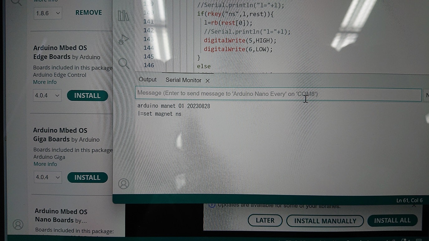
Serial.println("MTOF171000C0_I2C");
Wire.begin();
//M5.Lcd.println("MTOF171000C0_I2C");
//pinMode(18, OUTPUT);
delay(1000);
}
String rb(String x){
String rtn=x;
while(rtn.startsWith(" ")){
rtn=rtn.substring(1);
}
return rtn;
}
boolean rkey(String key, String x, String *rest){
if(x.startsWith(key)){
rest[0]=x.substring(key.length());
return true;
}
return false;
}
boolean isDec(char c){
if('0'<=c && c<='9') return true;
return false;
}
boolean rpint(String x, int n[], String *rest){
int nx=0;
int cx=0;
//return_result("rping "+x);
if(!isDec(x.charAt(0))){
rest[0]=x;
return false;
}
cx=x.charAt(0)-'0';
nx=cx;
//return_result("rpint-1");
n[0]=nx;
//return_result("rpint-2");
if(x.length()<=0) return true;
x=x.substring(1);
//return_result("rpint-3 x="+x);
while(isDec(x.charAt(0))){
cx=x.charAt(0)-'0';
nx=nx*10+cx;
if(x.length()<=0) break;
x=x.substring(1);
//return_result("rpint-4 x="+x+"nx="+String(nx));
if(x.length()<=0) break;
}
//return_result("rpint-5");
rest[0]=x;
//return_result("rpint-6");
n[0]=nx;
return true;
}
boolean rStrConst(String in, String strc[], String rest[]){
String r="";
if(in.indexOf("\"")!=0) return false;
in=in.substring(1);
while(in.indexOf("\"")!=0){
if(in.length()<=0) return false;
if(in.charAt(0)=='\\'){
in=in.substring(1);
if(in.length()<=0) return false;
char x=in.charAt(0);
if(x=='n'){
r=r+"\n";
}
else
if(x=='"'){
r=r+"\"";
}
else
{
r=r+in.charAt(0);
}
}
else{
char x=in.charAt(0);
r=r+in.charAt(0);
}
in=in.substring(1);
}
strc[0]=r;
rest[0]=in;
return true;
}
boolean rHex(String in, long hex[], String rest[]){
String r;
long lx;
lx=0;
if(in.indexOf("0x")!=0) return false;
// Serial.println("rHex "+in+" ");
in=in.substring(2);
if(in.length()<=0) return false;
char x=in.charAt(0);
while(isHexadecimalDigit(x)){
if(isDigit(x)){
lx=lx*16+x-'0';
}
else
if(('a'<=x) && x<='f'){
lx=lx*16+x-'a'+10;
}
else
if('A'<=x && x<='F'){
lx=lx*16+x-'A'+10;
}
in=in.substring(1);
if(in.length()<=0) break;
x=in.charAt(0);
}
hex[0]=lx;
rest[0]=in;
//Serial.println(hex[0],HEX);
return true;
}
boolean rInt(String in, long ri[], String rest[]){
//Serial.print("rInt "+in+" ");
String r;
int sign;
long lx;
lx=0;
sign=1;
if(in.indexOf("-")==0){
sign=-1;
in=in.substring(1);
}
if(in.length()<=0) return false;
char x=in.charAt(0);
if(!isDigit(x)) return false;
while(isDigit(x)){
lx=lx*10+x-'0';
in=in.substring(1);
if(in.length()<=0) break;
x=in.charAt(0);
}
ri[0]=sign*lx;
//Serial.println(ri[0]);
rest[0]=in;
return true;
}
int thresh=0;
/*
command:
get distance. //get current tof results (length).
get thresh. //get current threshold.
set thresh <length(mm)>. //if tof results less than <length>, back. else stop. if 0, disable.
go.
back.
stop.
*/
void parse_line(String line){
String l=rb(line);
String strx[1];
String rest[1];
int nx[1];
Serial.println("l="+l);
if(rkey("get ",l,rest)){
l=rb(rest[0]);
//DebugSerial.println("l="+l);
if(rkey("distance",l,rest)){
String sx=String(distance);
//DebugSerial.println("sx="+sx);
return_result(sx);
}
else
if(rkey("thresh",l,rest)){
String sx=String(thresh);
//DebugSerial.println("sx="+sx);
return_result(sx);
}
}
else
if(rkey("set ",l,rest)){
l=rb(rest[0]);
int n;
//DebugSerial.println("l="+l);
if(rkey("thresh ",l,rest)){
l=rb(rest[0]);
if(rpint(l,nx,rest)){
n=nx[0];
thresh=n;
return_result("set thresh "+String(n));
//DebugSerial.println("n=");
//DebugSerial.println(n);
}
}
}
else
if(rkey("go",l,rest)){
goState="GO";
thresh=0;
}
else
if(rkey("back",l,rest)){
goState="BACK";
thresh=0;
}
else
if(rkey("stop",l,rest)){
goState="STOP";
thresh=0;
}
else
if(rkey("show ",l,rest)){
l=rb(rest[0]);
if(rStrConst(l,strx,rest)){
return_result(strx[0]);
}
}
}
// メイン処理 ************************************************************************
void loop() {
M5.update(); // ボタン状態更新
// 本体ボタン、外部ボタン入力処理
// ボタンA または 外部スイッチ赤が押されている なら
if (M5.BtnA.isPressed() ) {
//Serial.println("GO"); // 標準のシリアル出力
return_result("GO");
//Serial2.println("V_UP!"); // シリアル2出力
//da_val++; // アナログ出力 +1
thresh=0;
goState="GO";
}
// ボタンB または 外部スイッチ青が押されてる なら
if (M5.BtnB.isPressed() ) {
//Serial.println("BACK"); // 標準のシリアル出力
return_result("BACK");
//Serial2.println("V_DOWN!"); // シリアル2出力
//da_val--; // アナログ出力 -1
thresh=0;
goState="BACK";
}
// ボタンC または 外部スイッチ青が押されてる なら
if (M5.BtnC.isPressed() ) {
//Serial.println("STOP"); // 標準のシリアル出力
return_result("STOP");
//Serial2.println("V_DOWN!"); // シリアル2出力
//da_val--; // アナログ出力 -1
thresh=0;
goState="STOP";
}
// LCD表示処理
// ON/OFFボタン出力状態表示
M5.Lcd.setTextFont(4); // フォント
M5.Lcd.setCursor(26, 153); // 座標指定(x, y)
if (goState.equals("GO")) {
digitalWrite(HB1, LOW);
digitalWrite(HB2, HIGH);
M5.Lcd.setTextColor(CYAN, BLACK); // (文字色, 背景)
M5.Lcd.printf("GO "); // 出力端子の状態表示
M5.Lcd.fillCircle(10, 164, 8, RED); // 指定座標に半径を指定して塗り潰し円描画(x, y, r, 色)
}
else
if (goState.equals("BACK")){
digitalWrite(HB1, HIGH);
digitalWrite(HB2, LOW);
M5.Lcd.setTextColor(ORANGE, BLACK); // (文字色, 背景)
M5.Lcd.printf("BACK "); // 出力端子の状態表示
M5.Lcd.fillCircle(10, 164, 8, ORANGE); // 指定座標に半径を指定して塗り潰し円描画(x, y, r, 色)
}
else
if (goState.equals("STOP")){
digitalWrite(HB1, LOW);
digitalWrite(HB2, LOW);
M5.Lcd.setTextColor(MAGENTA, BLACK); // (文字色, 背景)
M5.Lcd.printf("STOP "); // 出力端子の状態表示
M5.Lcd.fillCircle(10, 164, 8, GREEN); // 指定座標に半径を指定して塗り潰し円描画(x, y, r, 色)
}
// バッテリー残量表示(表示更新10回に1回)
if (cnt == 10) { // サンプリング
M5.Lcd.setTextFont(1); // フォント
M5.Lcd.setCursor(295, 228); M5.Lcd.setTextColor(DARKGREY, BLACK); // 座標指定(x, y) // 文字色、背景
M5.Lcd.printf("%d%%", M5.Power.getBatteryLevel()); // バッテリー残量表示
cnt = 0; // サンプリング回数0リセット
}
//digitalWrite(18, LOW);
delay(5);
// Serial.print("distance = ");
Wire.beginTransmission(ADDRESS);
Wire.write(0xD3);
Wire.endTransmission(false);
Wire.requestFrom(ADDRESS, 2);
data_cnt = 0;
int dx = 0;
distance_tmp = 0;
while(Wire.available())
{
distance_tmp = Wire.read();
dx = (dx << (data_cnt*8)) | distance_tmp;
data_cnt++;
}
distance=dx;
// String lx=""+String(distance)+" mm";
// return_result(lx);
if(thresh>0){
if(distance>thresh){
goState="GO";
}
else{
goState="STOP";
}
}
delay(45);
while (Serial.available() > 0) {
char inChar = (char)Serial.read();
// Serial.print(inChar);
// add it to the inputString:
inputString += inChar;
// if the incoming character is a newline, set a flag so the main loop can
// do something about it:
if (inChar == '\n') {
//putLine(inputString);
parse_line(inputString);
inputString="";
//digitalWrite(13,LED_IS_ON);
//LED_IS_ON=1-LED_IS_ON;
}
}
cnt++; // 表示回数カウント +1
delay(100); // 遅延時間
}
中継プログラム(Raspberry Pi のM5Stackとの通信プログラム)
事前に、ipgetパッケージのinstallが必要です(pip3 install ipget)
from tkinter import *
import tkinter as tk
from tkinter import scrolledtext
import serial
import threading
# -*- coding:utf-8 -*-
# 20230503
#
from tkinter.ttk import Scale
from tkinter import colorchooser,filedialog,messagebox
import time
import math
import sys
import requests
import os
import socket
from collections import deque
import subprocess
import copy
import re
import ipget

class Remote_Command_Reader:
    sock = socket.socket(socket.AF_INET, socket.SOCK_STREAM)
    HOST = 'localhost'
    PORT = 9998
    def __init__(self,pd):
        print("start Remote_Command_Reader.__init__")
        self.gui=pd
        print(self.gui)
        self.gui.set_Remote_Command_Reader(self)
        self.my_address='localhost'
        self.get_my_address()

    def python2fwbln(self,py2x_message):
      msg=py2x_message+'\n'
      self.sock.sendall(msg.encode('utf-8'))

    def python2fwb(self,py2x_message):
      msg=py2x_message
      self.sock.sendall(msg.encode('utf-8'))

    def get_my_address(self):
        self.my_address = socket.gethostbyname(socket.gethostname())
        #ipx=ipget.ipget()
        #self.my_address=ipx.ipaddr("wlan0")
        return self.my_address

    def parse(self,line):
      #self.python2fwb(">"+line)
      self.gui.parse_command(line)

    def returnFileList(self):
        cpath=os.getcwd()
        os.chdir("/home/pi/Pictures")
        filenames = [f.name for f in os.scandir()]
        filenames.sort()
        for fn in filenames:
            self.python2fwbln(fn)
        os.chdir(cpath)
    def shutdown(self):
        os.system("sudo shutdown -h now")

    def client_start(self,addr):
      """クライアントのスタート"""
      try:
          self.sock.connect((addr, self.PORT))
          print("pi_arduino_uart_ex01.py connected to the server")
      except Exception as e:
          msg1="connect error, addr="+addr+" port="+str(self.PORT)
          print(msg1)
          self.gui.write_message(msg1)
          tb=sys.exec_info()[2]
          msg2="[message]{0}".format(e.with_traceback(tb))
          print(msg2)
          self.gui.write_message(msg2)
          return
      addr=self.sock.getsockname()[0]
      print("connect, addr="+addr)
      handle_thread = threading.Thread(target=self.handler, args=(self.sock,), daemon=True)
      handle_thread.start()

    def return_message(self,x):
        self.sock.send((x+'\n').encode('utf-8'))

    def handler(self,sock):
      """サーバからメッセージを受信し、表示する"""
      print("start handler from pic_ex04.py")
      while True:
          data=b''
          #data=sock.recv(1024)
          try:
              data = sock.recv(1024)
          except Exception as e:
              tb=sys.exec_info()[2]
              msg2="message]{0}".format(e.with_traceback(tb))
              print(msg2)
              self.gui.write_message(msg2)
          try:
              #print("[client-recv¡]{}".format(data.decode("utf-8")))
              received=data.decode("utf-8")
              lines=received.splitlines()
              for line in lines:
                  self.parse(line)
          except Exception as e:
              tb=sys.exec_info()[2]
              msg2="message]{0}".format(e.with_traceback(tb))
              print(msg2)
              self.gui.write_message(msg2)

class App:
    def __init__(self,master):
        self.root=root
        self.root.title("command panel")
        self.root.configure(background="white")
        self.root.geometry("850x600")
        self.server_label=Label(self.root, text='server addr')
        self.server_label.place(x=10,y=10)
        self.server_field=Entry(self.root, width=40)
        self.server_field.place(x=100,y=10)
        self.id_label=Label(self.root, text='id')
        self.id_label.place(x=10,y=40)
        self.id_field=Entry(self.root, width=40)
        self.id_field.place(x=100,y=40)
        #self.address_field=Entry(self.root, width=40)
        #self.address_field.place(x=100,y=10)
        self.command_label=Label(self.root, text='command')
        self.command_label.place(x=10,y=60)
        self.command_field=Entry(self.root, width=70)
        self.command_field.place(x=100,y=60)
        self.parse_command_button=Button(self.root, text='parse',bd=2,bg='white',
                                command=self.click_command_button,width=8, relief=RIDGE)
        self.parse_command_button.place(x=700,y=60)

        self.arduino_command_label=Label(self.root, text='arduino')
        self.arduino_command_label.place(x=10,y=90)
        self.arduino_command_field=Entry(self.root, width=70)
        self.arduino_command_field.place(x=100,y=90)
        self.arduino_send_button=Button(self.root, text='send',bd=2,bg='white',
                                command=self.arduino_click_button,width=8, relief=RIDGE)
        self.arduino_send_button.place(x=700,y=90)

        self.message_frame=tk.Frame(self.root,width=100, height=30)
        self.message_frame.place(x=30,y=120)
        self.message_area=scrolledtext.ScrolledText(self.message_frame)
        self.message_area.pack()
        self.message_line=0

        self.id_field.delete(0,END)
        self.id_field.insert(END,'')

        self.serial=serial.Serial('/dev/ttyACM0',115200)
        self.serial.flush()
        thread=threading.Thread(target=self.read_loop,args=[],name='thread1')
        ipx=ipget.ipget()
        self.send_arduino("show "+"\"ip_addr= "+str(ipx.ipaddr('wlan0'))+"\"")
        thread.start()

# Functions are defined here
    def set_Remote_Command_Reader(self,reader):
        self.reader=reader

    def set_tcp_server_address(self,address):
        self.server_field.delete(0,END)
        self.server_field.insert(END,address)

    def connect(self):
        server=self.server_field.get()
        self.reader.client_start(server)

    def shutdown(self):
        os.system("sudo shutdown -h now")

    def write_message(self,message):
        self.message_area.insert(tk.END,message)
        self.message_area.insert(tk.END,'\n')
    def send_arduino(self,message):
        self.serial.write(message.encode('utf-8'))
        self.write_message(">"+message)
        self.serial.write('\n'.encode('utf-8'))

    def arduino_click_button(self):
        inx=self.arduino_command_field.get()
        print("inx="+inx)
        self.send_arduino(inx)
        self.arduino_command_field.delete(0,END)

    def click_command_button(self):
        inx=self.command_field.get()
        print("inx="+inx)
        self.parse_command(inx)
        self.command_field.delete(0,END)

    def set_my_id(self,id):
        self.id_field.delete(0,END)
        self.id_field.insert(END,id)

    def is_my_id(self,x):
        print("is_my_id("+x+")",end="")
        id=self.id_field.get()
        print(" id="+id)
        return re.match(x,id)

    def read_loop(self):
        while True:
            c=self.serial.readline().decode('utf-8').rstrip()
            self.message_line=self.message_line+1
            self.write_message(c)
            #addr=self.server_field.get()
            #rtn=addr+" "+c
            print("return "+c)
            self.reader.return_message(c)
    #
    # command
    #    id="<id>" arduino <arduino command>
    #    arduino <arduino command>
    #    set id="<id>"
    #    shutdown
    #
    def parse_command(self,command):
        rest=[""]
        strc=[""]
        ix=[""]
        self.command_field.delete(0,END)
        self.command_field.insert(END,command)
        command=self.r_b(command)
        print("parse_command("+command+")")
        if self.parse_key("id=",command,rest):
            print("parse_key(id="+command+","+rest[0]+")")
            command=self.r_b(rest[0])
            if self.parse_String_Constant(command,strc,rest):
                print("strc="+strc[0]+",rest="+rest[0])
                command=self.r_b(rest[0])
                strcx=strc[0]
                if strcx=="*" :
                    if self.parse_arduino(command):
                        return True
                    else:
                        return False
                elif self.is_my_id(strcx):
                    print("start parse_arduino("+command+",rest)")
                    if self.parse_arduino(command):
                        return True
                    else:
                        return False
                else:
                    return False
            return False
        elif self.parse_key("set ",command,rest):
            command=self.r_b(rest[0])
            if self.parse_key("id=",command,rest):
                command=self.r_b(rest[0])
                if self.parse_String_Constant(command,strc,rest):
                    strcx=strc[0]
                    print("strc="+strcx+",rest="+rest[0])
                    self.set_my_id(strcx)
                    return True
                else:
                    return False
            else:
                return False
        elif self.parse_key("shutdown",command,rest):
            self.shutdown()
            return True

    def parse_arduino(self,command):
        rest=[""]
        strc=[""]
        ix=[""]
        command=self.r_b(command)
        if self.parse_key("arduino ",command,rest):
            print("parse_key(arduino "+command+","+rest[0]+")")
            command=self.r_b(rest[0])
            print("xx "+command)
            self.arduino_command_field.delete(0,END)
            self.arduino_command_field.insert(END,command)
            self.send_arduino(command)
            return True
        else:
            return False

    def parse_key(self,key,inx,rest):
        keylen=len(key)
        inlen=len(inx)
        if inx.startswith(key):
            rest[0]=inx[keylen:inlen]
            return True
        rest[0]=inx
        return False

    def parse_p_int(self,command,ix,rest):
        print("parse_p_int("+command+",ix,rest)")
        i=0
        c=command[0]
        if c in ['0','1','2','3','4','5','6','7','8','9']:
            clen=len(command)
            while True:
                i=i*10+int(c)
                command=command[1:clen]
                clen=len(command)
                if clen==0:
                    ix[0]=i
                    rest[0]=""
                    return True
                print("parse_p_int command="+command)
                c=command[0]
                if not (c in ['0','1','2','3','4','5','6','7','8','9']):
                    ix[0]=i
                    rest[0]=command
                    return True
        rest[0]=command
        ix[0]=0
        return False

    def r_b(self,inx):
        rx=[""]
        while self.parse_key(" ",inx,rx):
            inx=rx[0]
        return rx[0]

    def parse_String_Constant(self,inx,strc,rest):
        rx=[""]
        xstr=""
        if self.parse_key('"',inx,rx):
            inx=rx[0]
            fx=inx[0]
            xlen=len(inx)
            while fx!='"':
                if xlen==0:
                    return False
                if fx=='\\':
                   inx=inx[1:xlen]
                else:
                   xstr=xstr+fx
                xlen=len(inx)
                inx=inx[1:xlen]
                fx=inx[0]
            if self.parse_key('"',inx,rx):
                strc[0]=xstr
                rest[0]=rx[0]
                return True
        return False

if __name__=="__main__":
    root = Tk()
    root.wm_title('Scrolling')
    app = App(root)
    rcr=Remote_Command_Reader(app)
    ip=rcr.get_my_address()
    app.set_tcp_server_address(ip)
    app.connect()
    ip=rcr.get_my_address()
    app.set_tcp_server_address(ip)
    app.set_my_id(ip)
    root.mainloop()
Raspberry Pi 間通信の中継プログラム(Chat Server)
import socket
import threading
import subprocess

HOST = ''
PORT = 9998
clients = []


def remove_conection(con, address):
    """クライアントと接続を切る"""

    print('[切断]{}'.format(address))
    con.close()
    clients.remove((con, address))


def server_start():
    """サーバをスタートする"""

    sock = socket.socket(socket.AF_INET, socket.SOCK_STREAM)
    sock.setsockopt(socket.SOL_SOCKET, socket.SO_REUSEADDR, 1)
    sock.bind((HOST, PORT))
    sock.listen(10)
    subprocess.Popen("python3 /home/pi/python/pi_arduino_uart_ex01.py",shell=True)
    while True:
        con, address = sock.accept()
        print("[接続]{}".format(address))
        clients.append((con, address))
        handle_thread = threading.Thread(target=handler,
                                         args=(con, address),
                                         daemon=True)
        handle_thread.start()


def handler(con, address):
    """クライアントからデータを受信する"""

    while True:
        try:
            data = con.recv(1024)
        except ConnectionResetError:
            remove_conection(con, address)
            break
        else:
            if not data:
                remove_conection(con, address)
                break
            else:
                print("[受信]{} - {}".format(address, data.decode("utf-8")))
                for c in clients:
                    if c[0]!=con:
                        while data:
                          n = c[0].sendto(data,c[1])
                          data = data[n:]

if __name__ == "__main__":
    server_start()
main controller
(まだ途中です。)
https://www2.yama-lab.org/class/maker/Real2Virtual202111/index.php?main_controller_01.py
ネオジム磁石の脅威
テスラダイスは、テスラダイス同士の結合に、6面体の各面に相補的に配置されたネオジム磁石を使っています。
電磁石を使ったテスラダイスの把握・分離機構を作っていて、ネオジム磁石の凄さを思い知りました。大変です。今回の思惑がうまくいかないかもしれません。
電流を流さないのにくっつく
今使っている電磁石は鉄心を持っています。鉄心は磁石にくっつきます。したがって、ネオジム磁石にもくっつきます。これ、電流を流していなくてもくっつきます。鉄心をとりはずしたら良いのでは?という提案をいただいたので、やってみたのですが、鉄心がないとぜんぜん磁力が足りなくて、くっつくときにくっつきませんでした。
電流の向きを変えても離れない
それじゃ、電流の向きを変えてみよう、ということで変えてみたのですが、鉄心がネオジム磁石で磁化されてしまっていて(ヒステリシスの影響?)電流を逆にしてもくっついたままでした。
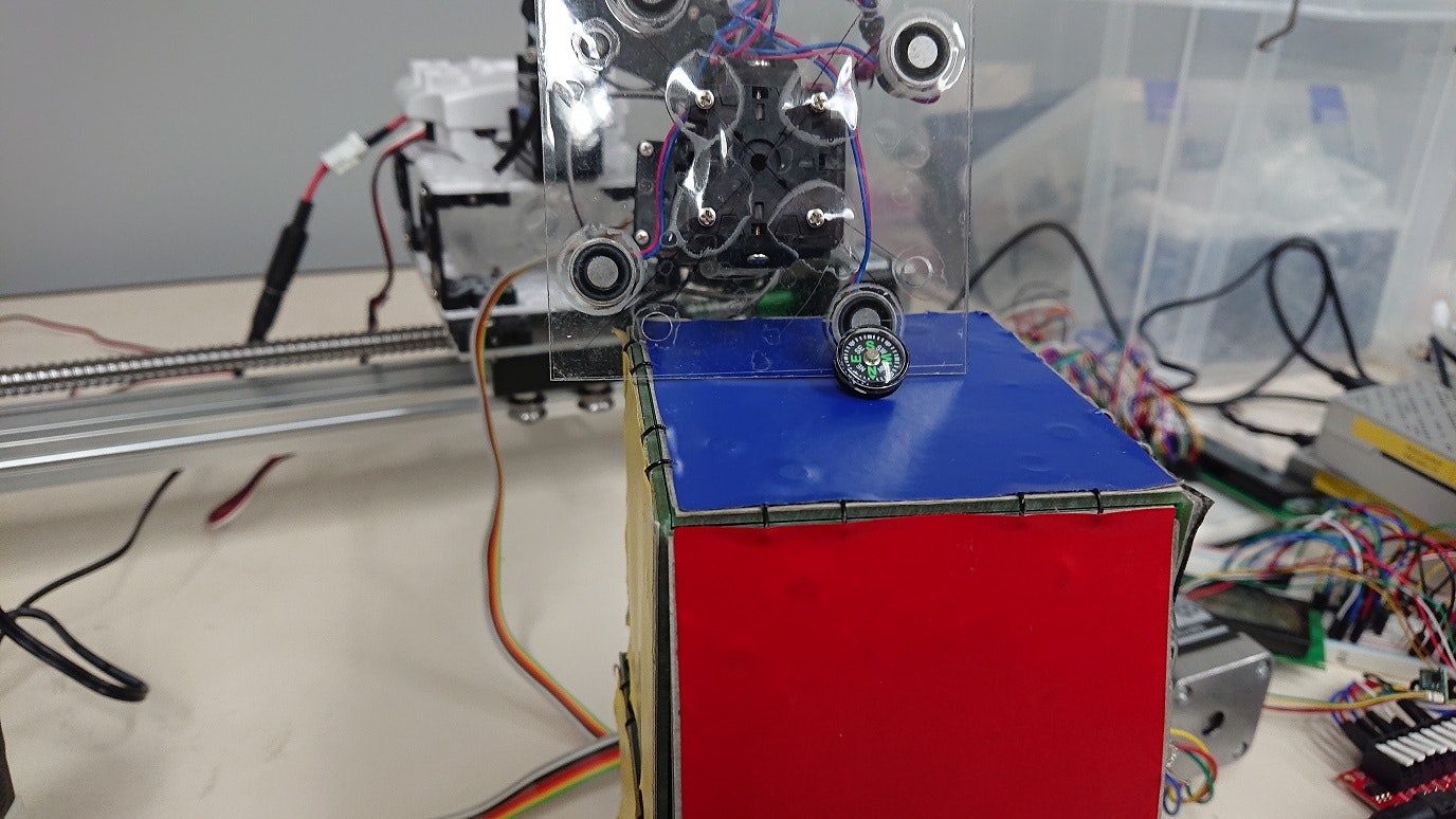
まず、電流の向きを順方向に流して、電磁石のそばに置いた方位磁石の向きを見ます。
方位磁石のSが電磁石に吸い寄せられているので、電磁石のこちら側の中心はNになっていることがわかります。
次に、電流の向きを逆方向にして、電磁石のそばに置いた方位磁石の向きを見ます。
方位磁石の向きは変わりません。方位磁石のSが電磁石に吸い寄せられたままです。
方位磁石が逆方向に磁化してしまう。
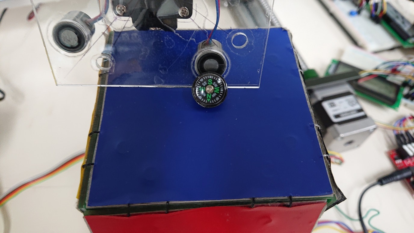
これはネオジム磁石は関係ないかもしれませんが、一連の実験で磁界の方向を検知するため、方位磁石を使っていました。ところが、いつの間にか、方位磁石が逆向きに磁化されてしまい、北と南が入れ替わってしまいました。
この写真の上の方がじつは北。
磁界計の製作
上の実験で、方位磁石が役に立たないことが分かったので、手元にあった、サンハヤトの9軸慣性センサモジュールMM-9DS1とM5Stackを使って、磁界計(x,y,zの方向と強さの計測)を作りました。
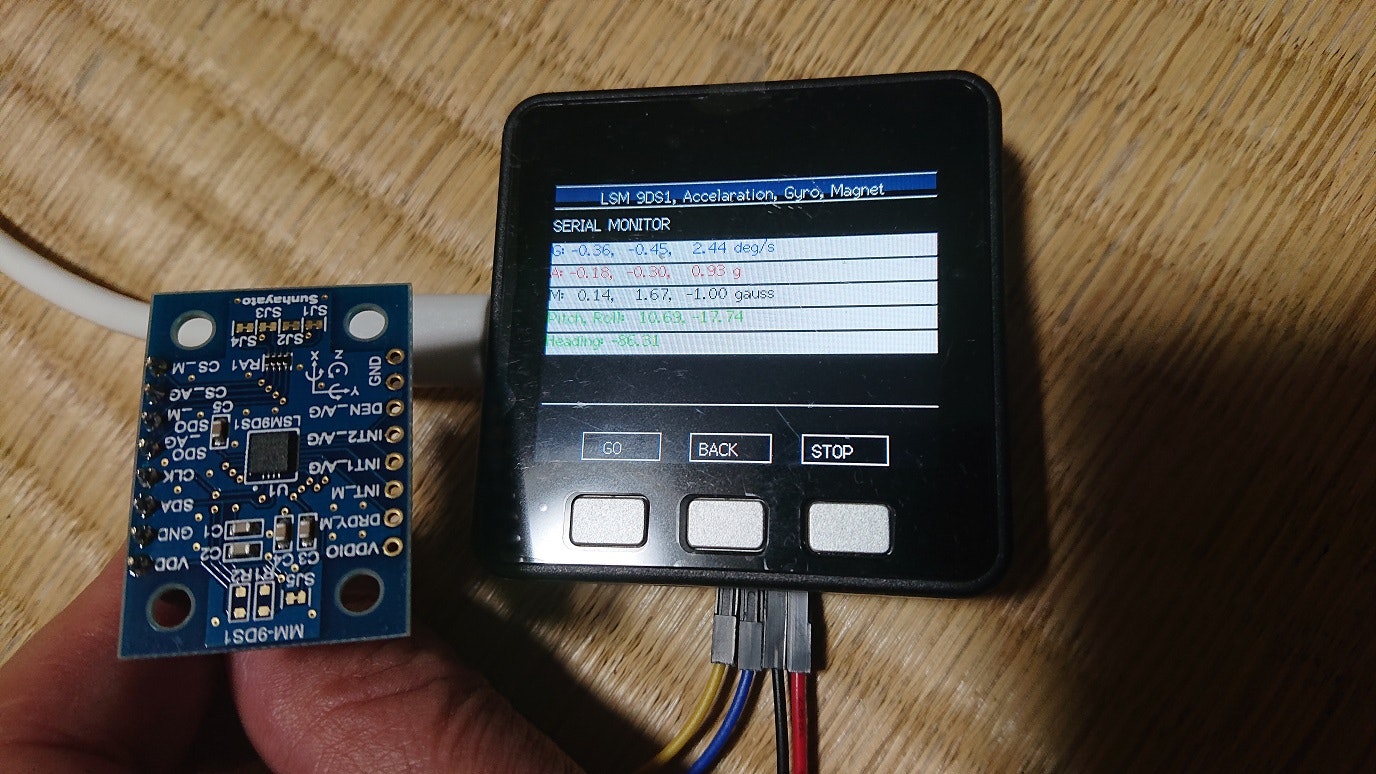
上の写真がその磁界計です。白いエリアの上から3行目が磁力の(x,y,z)の方向を示しています。ここでは(x,y,z)=(0.14,1.67,-1.00)となっています。
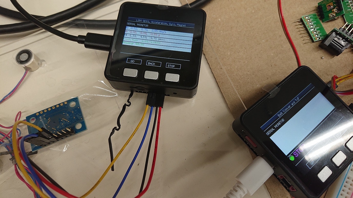
早速、磁界計で床の把握・分離機構の磁界の計測。電流が流れていない時。Z方向ではなくy方向が値が大きいのは、地磁気のせい?
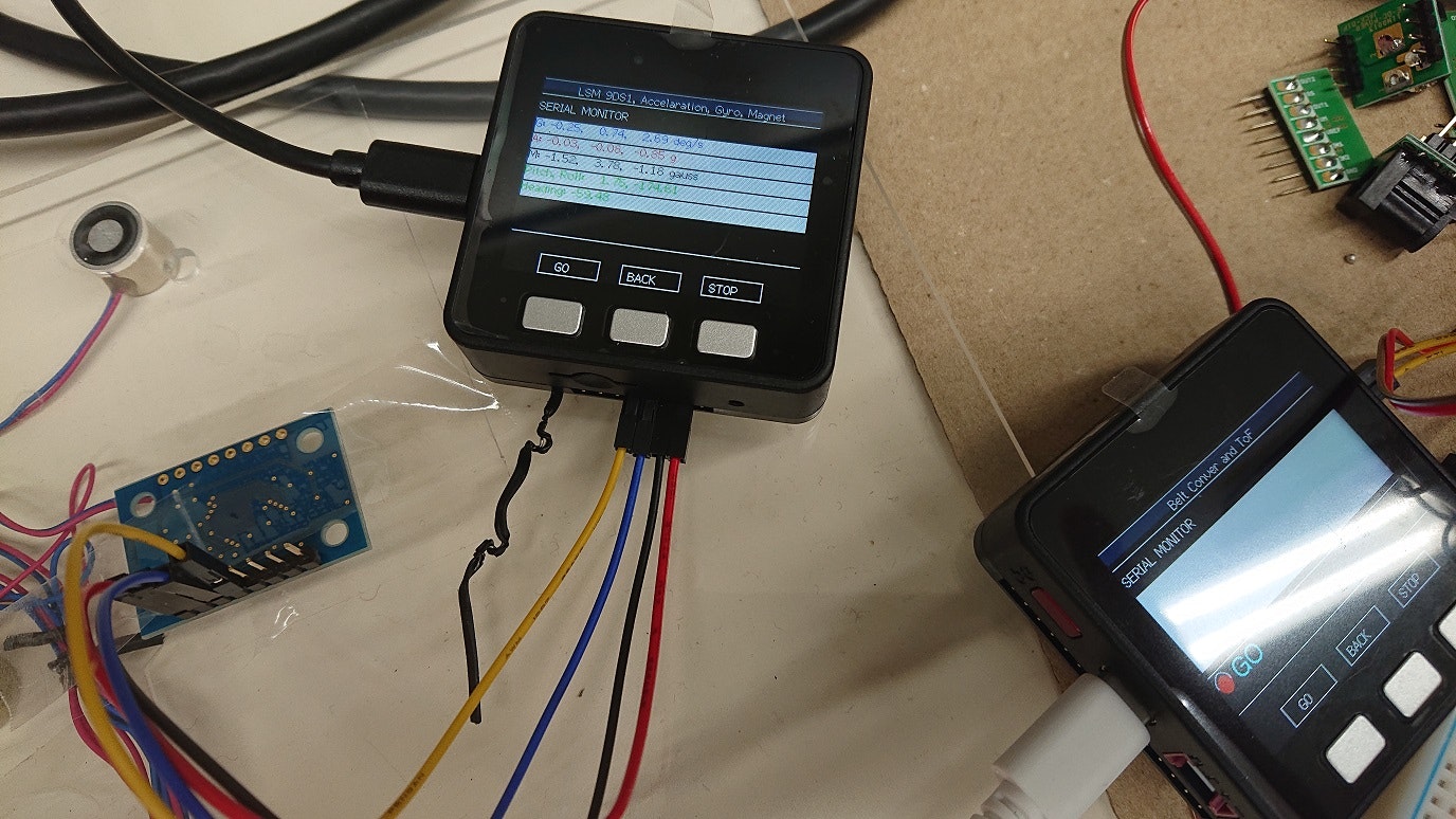
順方向に電流を流した時。(x,y,z)=(1.33,4.59,-1.71)
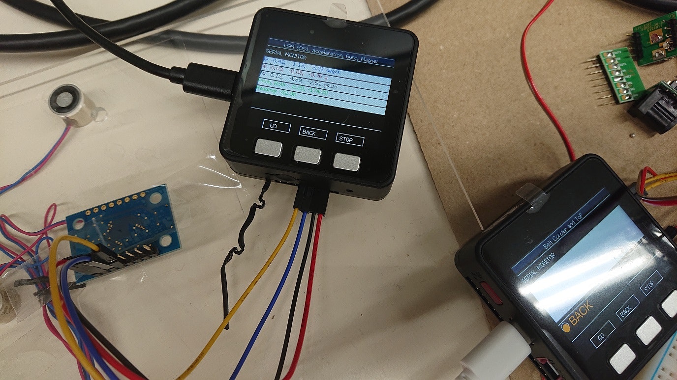
逆方向に電流を流した時。(x,y,z)=(-1,52, 3.78 -1.18)
センサを直接電磁石に近づけてZ方向の磁界を測ると、もしかしたら、そのすぐそばの、電磁石を囲んでいる鉄のカバーの磁界の影響を受けるのかも、と思い、電磁石の鉄心の上に、ただの鉄心を載せ、そのうえにセンサを立てて置いて、y方向で電磁石の磁界を測るようにしてみました。これは、電流を流していない時。y方向の磁力は4.59 Gaussでした。(x,y,z)=(-0.94, 4.59, -0.81)
これ(上の写真)は順方向に電流を流した時。磁界はほとんど変わりません
。(x,y,z)=(-0.68, 4.59,-0.91)
ところが、逆方向に電流を流すと、上に置いた鉄心とセンサが反発力を受けて倒れてしまいました。再度、片方の手で鉄心とセンサを支えて、もう片方の手で撮影したのが上の写真です。
見えにくいですが、y方向の磁力が 1.53 Gauss, と、順方向と比べて、かなり小さくなっています。(x,y,z)=(-1.16,1.53,-0.92)
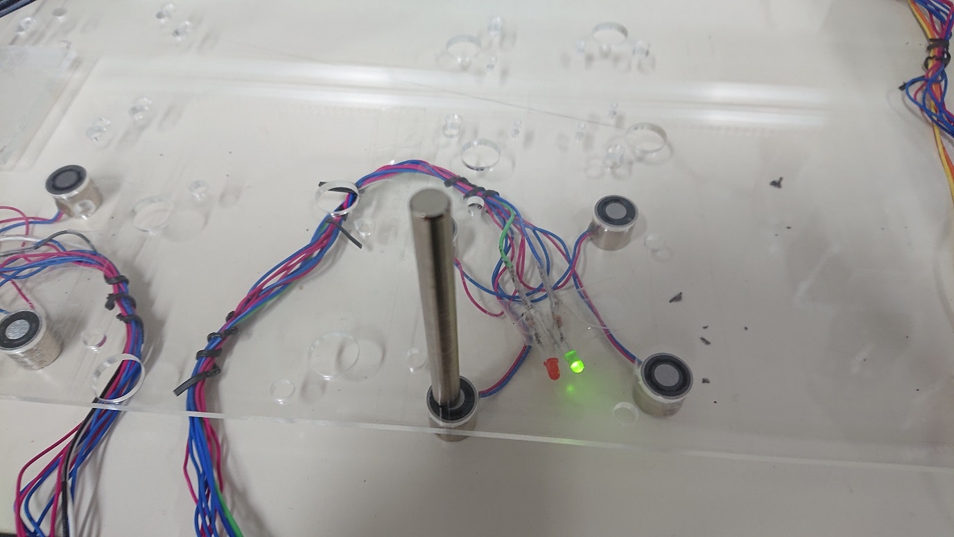
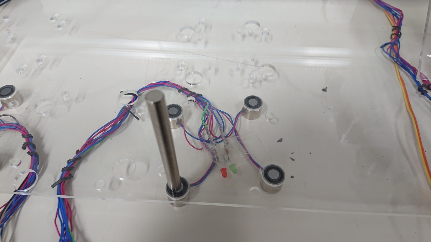
電磁石の動作状況の可視化
磁界は人の目には直接はみえません。せめて、電流をながしているときに、その向きと電流の有無がわかるように、と、テスラダイスの把握・分離機構に、2つの、異なる色の発光ダイオードを付けて、電流が流れていることの有無とその向きがわかるようにしました。発光ダイオードはダイオードなので、これが簡単に実現できますね。
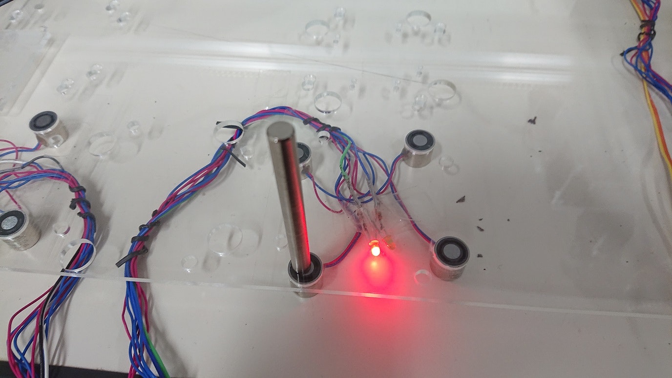
順方向に電流を流した時。このとき、電磁石の上に載っている鉄心は、電磁石の鉄心としっかりくっついていました。
逆方向に電流を流した時。このとき、電磁石の上に載っている鉄心は、その下の電磁石の鉄心と反発していました。この写真ではたまたま倒れていませんが、ちょっと斜めにするとすぐに倒れます。
方位磁石で磁界を計測していた時は同じ極でくっついたままだったのですが、どうしたのかな?
電流を流していない時。電磁石の上に載っている鉄心は、その鉄心が磁化していたためか、下の電磁石の鉄心とくっついていました。
うまくいくかどうかまだわかりません。
テスラダイスの把握・分離について、アームロボットに付けた電磁石と、床に付けた電磁石の、次回の向きと強さによって、その差で、電流の有無にかかわらずくっついてしまう現象がなんとか解決できないか?と思っていますが、まだ検証ができていません。さて、どうなるでしょうか?
まとめ
電磁石を使った、ある物体(テスラダイス)の把握・分離を試みていることについて書きました。もう、公開時間が迫っているので、とりあえず、ここで公開します。生まれて初めてのQiitの投稿です。公開後の、文章や写真の追加・削除を許してください。
その後
2024年 7月17日、あと少し。
2024年 8月14日
テスラダイスが2個の場合のテレポーテーションに成功しました。