はじめに
ロボットというのは万能ではありません.ロボットは大抵何らかの駆動システムを持ち,環境との相互作用によってとある場所まで移動したり,ボディの姿勢を変更したりします.
実環境で動作する以上,ロボットはつねにルールに縛られた状態で動かねばなりません.もっと言えば,ダイナミクスやキネマティクスといった物理法則や,モータ駆動トルク限界のような制約を無視した動きはできません.もしできたら多分設計ミスです.
自律ロボットにおけるプランニングとは,ロボットを所望の状態まで遷移させるための中間動作を事前に"計画"することです.
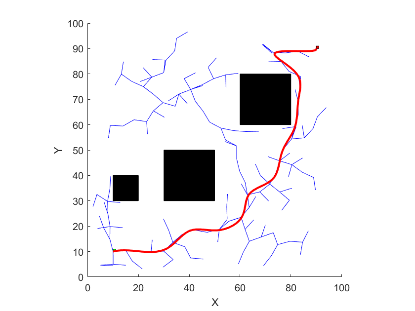
例えば目標地点まで移動する経路計画問題を考えてみます.ランダムサンプリングアルゴリズムの一種であるRapidly-exploring Random Tree (RRT)を用いて,実際に経路計画を行ってみた結果が下図です.

スタート地点を$[x,y]=[10,10]$,ゴール地点を$[x,y]=[90,90]$に設定しています.黒塗りの四角形が障害物を表しており,これを回避するような経路が生成されています.
さすがにこんなカクカクした動きをロボットにさせるわけにはいかないので,スプライン補間を使って平滑化してみます.

無事に滑らかな移動経路を生成することができました.
さて,ロボットは本当にこの経路に沿って移動すれば,目標地点まで到達できるのでしょうか?ゴール付近ではパスが急激に折れ曲がっています.旋回性能が十分でなければ,ロボットはうまく追従できずに経路から大きく外れてしまうでしょう.
このような経路が生成されてしまうのは,ベーシックなRRTはロボットの制約条件を考慮していないからです.
RRT*を使うとかすればムダな旋回のないパスが生成できるじゃん!という意見もあるはずです.ただここで言いたいのは,諸々の制約を確実に満たす=動作可能なことが保証された経路を生成してほしいということです.このようなダイナミクス/キネマティクスを考慮したプランニングのことを"Kinodynamic Planning"と呼びます.
以上の背景のもとで,本投稿ではRRTを派生させたKinodynamic RRTという手法を紹介してみたいと思います.実はこのKinodynamic RRT,ベーシックなRRTアルゴリズムの一部を変えるだけで,とても簡単に実現できます.
アルゴリズム
ベーシックなRRT
まずはベーシックなRRTのアルゴリズムを見てみましょう.
- ランダムに点($x_{rand}$)をエリア内から選ぶ(とある頻度でゴール地点を選ぶ)
- $x_{rand}$に最も近い点($x_{nearest}$)をTreeから探索する
- $x_{nearest}$から$x_{rand}$に向かって一定距離のばした点($x_{new}$)をTreeに加える
- ゴールに到達するまで1~3の手順を繰り返す
見ての通りすごくシンプルですね.はじめにで紹介したRRTも上のアルゴリズムで経路生成を行っています.
Kinodynamic RRT
これに対して,Kinodynamic RRTのアルゴリズムは以下です.
- ランダムに点($x_{rand}$)をエリア内から選ぶ(とある頻度でゴール地点を選ぶ)
- $x_{rand}$に最も近い点($x_{nearest}$)をTreeから探索する
- $x_{nearest}$を初期値として,制御入力$u$ を与えて1ステップだけ時間伝搬させた地点($x_{new}$)をTreeに加える
- ゴールに到達するまで1~3の手順を繰り返す
赤字で示したところが修正箇所になります.これだけです!
ベーシックなRRTでは$x_{nearest}$と$x_{rand}$をつなぐ直線上に$x_{new}$を生成していました.一方でKinodynamic RRTでは制御入力$u$ をもとに時間伝搬させており,これによってダイナミクス・キネマティクス的に成立する$x_{new}$を生成する仕組みになっています.
では制御入力は具体的にどう設定するのか?という話ですが,これは様々な方法があります.原著論文1には以下のように書かれています.
入力uは,ランダムに選ぶこともできるし,あらゆる入力を試して,サンプル点にできるだけ近づくようなものを選ぶこともできる.
「ランダムに選ぶ」については説明不要ですね.駆動系のスペックを考慮した範囲で,ランダムにサンプリングすればよいだけです.
もう一つの選択方法についても文章からイメージできると思いますが,一応数式でも示しておきます.点同士の"距離"という概念を以下のように定義しておきます2.
dist(x_1,x_2) = ||W(x_1-x_2)||_2
$W$は対角行列であり,重み付きの誤差を計算しているだけです.
この定義を用いると,設定する制御入力$u^*$は以下のように計算できます.
\newcommand{\argmin}{\mathop{\rm argmin}\limits}
u^* = \argmin_{u_i}{dist(f(x_{nearest},u_i),x_{rand})} \\
求めた制御入力を用いて,$x_{new}$は以下のように計算されます.なお,$f(x,u)$はシステムのダイナミクスを表しています.
x_{new} = f(x_{nearest},u^*)
実践編 ~差動二輪型ロボットの経路計画~
ここでは差動二輪型のロボットを例にとって,Kinodynamic RRTを使うことでどういった経路が生成されるのかを見ていきたいと思います.本ロボットは非ホロノミック系であり,真横方向には移動できないといった制約があるため題材としてぴったりです.
ロボットモデル
2次元平面上のロボット状態を,位置$x,y$,Yaw角$\theta$の3変数として定義します.
左右の車輪角速度をそれぞれ$\omega_l, \omega_r$とすると,差動二輪の運動学モデルは以下のようになります.
\begin{bmatrix}
\dot{x} \\
\dot{y} \\
\dot{\theta}
\end{bmatrix}
=
\begin{bmatrix}
\frac{r}{2}\cos{\theta} & \frac{r}{2}\cos{\theta} \\
\frac{r}{2}\sin{\theta} & \frac{r}{2}\sin{\theta} \\
-r/d & -r/d
\end{bmatrix}
\begin{bmatrix}
\omega_l \\
\omega_r
\end{bmatrix}
シミュレーション
それではシミュレーション上で動作検証を行ってみます.今回はMatlabで実装してみました.作成したプログラムは一番下に載せています.
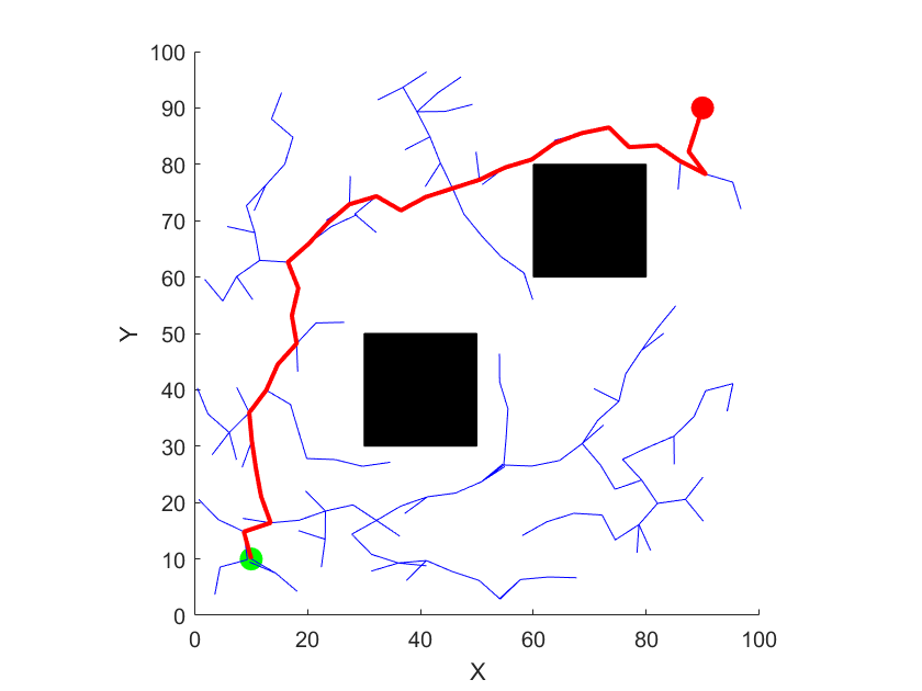
まずベーシックRRTを使って生成した経路を見てみます.案の定カクカクした経路が生成されています.

次にKinodynamic RRTを使って生成した経路です.こちらはキネマティクス制約を満たしつつ滑らかな経路が生成できていることが分かります.

プログラム:ベーシックRRT
※障害物判定チェックに線分と矩形の交差判定関数を用いてますが,間違えて2直線の交差判定処理になってますね...時間あれば直しておきます;
main_rrt.m
clc;
clear;
close all;

%% PARAMETERS
aux.start = [10, 10];
aux.goal = [90, 90];
aux.x_limits = [0, 100];
aux.y_limits = [0, 100];
aux.step_size = 5;
aux.max_iter = 10000;
aux.goal_tolerance = 5;
aux.obstacles = [30 30 20 20; 60 60 20 20]; % 障害物リスト
aux.goal_sample_rate = 10;  % ゴール地点のサンプリングレート (per 100 trials)

%% MAIN
% RRTインスタンスを作成
rrt = RRT(aux);

% RRTを実行
[path, success] = rrt.run();

%% OUTPUT
% 描画
figure;
hold on;
xlim(aux.x_limits);
ylim(aux.y_limits);
pbaspect([1 1 1])
xlabel("X");
ylabel("Y");

% 開始点とゴール点
plot(aux.start(1), aux.start(2), 'go', 'MarkerSize', 10, 'MarkerFaceColor', 'g');
plot(aux.goal(1), aux.goal(2), 'ro', 'MarkerSize', 10, 'MarkerFaceColor', 'r');

% 障害物の描画
for i = 1:size(aux.obstacles, 1)
    rectangle('Position', aux.obstacles(i, :), 'FaceColor', 'k');
end

% 木の描画
for i = 2:size(rrt.tree, 1)
    parent_idx = rrt.parent(i);
    plot([rrt.tree(i, 1), rrt.tree(parent_idx, 1)], ...
         [rrt.tree(i, 2), rrt.tree(parent_idx, 2)], 'b');
end

% 結果の描画
if success
    disp('ゴールに到達しました!');
    plot(path(:, 1), path(:, 2), 'r', 'LineWidth', 2);
else
    disp('ゴールに到達できませんでした。');
end

hold off;
RRT.m
classdef RRT < handle
    properties
        start
        goal
        x_limits
        y_limits
        step_size
        max_iter
        goal_tolerance
        obstacles
        tree
        parent
        goal_sample_rate
    end

    methods
        % コンストラクタ
        function obj = RRT(aux)
            obj.start = aux.start;
            obj.goal = aux.goal;
            obj.x_limits = aux.x_limits;
            obj.y_limits = aux.y_limits;
            obj.step_size = aux.step_size;
            obj.max_iter = aux.max_iter;
            obj.goal_tolerance = aux.goal_tolerance;
            obj.obstacles = aux.obstacles;
            obj.tree = aux.start; % Tree initialization
            obj.parent = 0;   % Parent initialization
            obj.goal_sample_rate = aux.goal_sample_rate;
        end

        % RRTアルゴリズムの実行
        function [path, success] = run(obj)
            success = false;
            for iter = 1:obj.max_iter
                % ランダムサンプリング
                if(rand*100 < obj.goal_sample_rate)
                    rand_point = obj.goal;
                else
                    rand_point = [rand * obj.x_limits(2), rand * obj.y_limits(2)];
                end

                % 最も近いノードを探索
                distances = vecnorm(obj.tree - rand_point, 2, 2);
                [~, nearest_idx] = min(distances);
                nearest_node = obj.tree(nearest_idx, :);

                % 新しいノードの計算
                direction = (rand_point - nearest_node) / norm(rand_point - nearest_node);
                new_node = nearest_node + obj.step_size * direction;

                % 新しいノードが範囲内かつ障害物内にないかチェック
                if obj.in_bounds(new_node) && ~obj.collides(nearest_node, new_node)
                    % 新しいノードを木に追加
                    obj.tree = [obj.tree; new_node];
                    obj.parent = [obj.parent; nearest_idx];

                    % ゴールに近いか確認
                    if norm(new_node - obj.goal) < obj.goal_tolerance
                        success = true;
                        break;
                    end
                end
            end

            % 経路を再構築
            if success
                path = [obj.goal];
                current = size(obj.tree, 1);
                while current > 0
                    path = [obj.tree(current, :); path];
                    current = obj.parent(current);
                end
            else
                path = [];
            end
        end

        % 範囲内チェック
        function result = in_bounds(obj, point)
            result = point(1) >= obj.x_limits(1) && point(1) <= obj.x_limits(2) && ...
                     point(2) >= obj.y_limits(1) && point(2) <= obj.y_limits(2);
        end

        % 障害物衝突チェック
        function result = collides(obj, node1, node2)
            result = false;
            for i = 1:size(obj.obstacles, 1)
                obs = obj.obstacles(i, :);
                x_min = obs(1);
                x_max = obs(1) + obs(3);
                y_min = obs(2);
                y_max = obs(2) + obs(4);
                if obj.line_intersects_rect(node1, node2, x_min, x_max, y_min, y_max)
                    result = true;
                    return;
                end
            end
        end

        % 線分と矩形の交差判定
        function result = line_intersects_rect(~, p1, p2, x_min, x_max, y_min, y_max)
            line = @(x, y) (p2(1) - p1(1)) * (y - p1(2)) - (p2(2) - p1(2)) * (x - p1(1));
            corners = [x_min, y_min; x_max, y_min; x_max, y_max; x_min, y_max];
            signs = arrayfun(@(x, y) sign(line(x, y)), corners(:, 1), corners(:, 2));
            result = any(signs ~= signs(1));
        end
    end
end
プログラム:Kinodynamic RRT
main_kino_rrt.m
clc;
clear;
close all;

% パラメータ設定
aux.start = [10, 10, 1/2*pi]; % 初期位置 [x, y, theta]
aux.goal = [90, 90, 0];  % ゴール位置 [x, y, theta]
aux.x_limits = [0, 100];
aux.y_limits = [0, 100];
aux.max_iter = 10000;
aux.goal_tolerance = 3;
aux.step_time = 0.1; % 1ステップの時間
aux.max_speed = 20; % 車輪の最大速度
aux.wheel_base = 5; % 車輪間の距離
aux.obstacles = [30 30 20 20; 60 60 20 20]; % 障害物リスト
aux.goal_sample_rate = 10;  % ゴール地点のサンプリングレート (per 100 trials)

% KRRTインスタンスを作成
krrt = KRRT(aux);

% KRRTを実行
[path, success] = krrt.run();

% 描画
figure;
hold on;
xlim(aux.x_limits);
ylim(aux.y_limits);
pbaspect([1 1 1])
xlabel("X");
ylabel("Y");

% 開始点とゴール点
plot(aux.start(1), aux.start(2), 'go', 'MarkerSize', 10, 'MarkerFaceColor', 'g');
plot(aux.goal(1), aux.goal(2), 'ro', 'MarkerSize', 10, 'MarkerFaceColor', 'r');

% 障害物の描画
for i = 1:size(aux.obstacles, 1)
    rectangle('Position', aux.obstacles(i, :), 'FaceColor', 'k');
end

% 木の描画
for i = 2:size(krrt.tree, 1)
    parent_idx = krrt.parent(i);
    plot([krrt.tree(i, 1), krrt.tree(parent_idx, 1)], ...
         [krrt.tree(i, 2), krrt.tree(parent_idx, 2)], 'b');
end

% 結果の描画
if success
    disp('ゴールに到達しました!');
    plot(path(:, 1), path(:, 2), 'r', 'LineWidth', 2);
else
    disp('ゴールに到達できませんでした。');
end

hold off;
KRRT.m
classdef KRRT < handle
    properties
        start
        goal
        x_limits
        y_limits
        max_iter
        goal_tolerance
        step_time
        max_speed
        wheel_base
        obstacles
        tree
        parent
        inputs
        goal_sample_rate
    end

    methods
        % コンストラクタ
        function obj = KRRT(aux)
            obj.start = aux.start; % [x, y, theta]
            obj.goal = aux.goal;   % [x, y, theta]
            obj.x_limits = aux.x_limits;
            obj.y_limits = aux.y_limits;
            obj.max_iter = aux.max_iter;
            obj.goal_tolerance = aux.goal_tolerance;
            obj.step_time = aux.step_time; % 制御入力を適用する時間
            obj.max_speed = aux.max_speed; % 車輪の最大速度
            obj.wheel_base = aux.wheel_base; % 車輪間の距離
            obj.obstacles = aux.obstacles;
            obj.tree = aux.start; % 木の初期化
            obj.parent = 0;   % 各ノードの親ノード
            obj.inputs = [];  % 制御入力リスト
            obj.goal_sample_rate = aux.goal_sample_rate;
        end

        % KRRTアルゴリズムの実行
        function [path, success] = run(obj)
            success = false;
            for iter = 1:obj.max_iter
                % ランダムな状態を生成
                if(rand*100 < obj.goal_sample_rate)
                    rand_state = [obj.goal, rand * 2 * pi];
                else
                    rand_state = [rand * obj.x_limits(2), rand * obj.y_limits(2), rand * 2 * pi];
                end

                % 最も近いノードを探索
                distances = vecnorm(obj.tree(:, 1:2) - rand_state(1:2), 2, 2); % 位置のみで評価
                [~, nearest_idx] = min(distances);
                nearest_state = obj.tree(nearest_idx, :);

                % ランダムな制御入力を生成
                [vr, vl] = obj.random_inputs();

                % 制御入力を適用し新しい状態を計算
                new_state = obj.simulate_dynamics(nearest_state, vr, vl, obj.step_time);

                % 新しい状態が範囲内かつ障害物に衝突していないか確認
                if obj.in_bounds(new_state) && ~obj.collides(nearest_state, new_state)
                    % 新しい状態を木に追加
                    obj.tree = [obj.tree; new_state];
                    obj.parent = [obj.parent; nearest_idx];
                    obj.inputs = [obj.inputs; vr, vl];

                    % ゴールに近いか確認
                    if norm(new_state(1:2) - obj.goal(1:2)) < obj.goal_tolerance
                        success = true;
                        break;
                    end
                end
            end

            % 経路を再構築
            if success
                path = [obj.goal];
                current = size(obj.tree, 1);
                while current > 0
                    path = [obj.tree(current, :); path];
                    current = obj.parent(current);
                end
            else
                path = [];
            end
        end

        % 動力学をシミュレーション
        function new_state = simulate_dynamics(obj, state, vr, vl, dt)
            % Differential drive kinematics
            theta = state(3);
            v = (vr + vl) / 2; % 平均速度
            omega = (vr - vl) / obj.wheel_base; % 角速度

            % 次の状態を計算
            dx = v * cos(theta) * dt;
            dy = v * sin(theta) * dt;
            dtheta = omega * dt;
            new_state = [state(1) + dx, state(2) + dy, wrapToPi(state(3) + dtheta)];
        end

        % 範囲内チェック
        function result = in_bounds(obj, state)
            result = state(1) >= obj.x_limits(1) && state(1) <= obj.x_limits(2) && ...
                     state(2) >= obj.y_limits(1) && state(2) <= obj.y_limits(2);
        end

        % 障害物衝突チェック
        function result = collides(obj, state1, state2)
            result = false;
            for i = 1:size(obj.obstacles, 1)
                obs = obj.obstacles(i, :);
                x_min = obs(1);
                x_max = obs(1) + obs(3);
                y_min = obs(2);
                y_max = obs(2) + obs(4);
                if obj.line_intersects_rect(state1(1:2), state2(1:2), x_min, x_max, y_min, y_max)
                    result = true;
                    return;
                end
            end
        end

        % ランダムな制御入力を生成
        function [vr, vl] = random_inputs(obj)
            vr = rand * obj.max_speed; % 0 ~ +max_speed
            vl = rand * obj.max_speed;
        end

        % 線分と矩形の交差判定
        function result = line_intersects_rect(~, p1, p2, x_min, x_max, y_min, y_max)
            line = @(x, y) (p2(1) - p1(1)) * (y - p1(2)) - (p2(2) - p1(2)) * (x - p1(1));
            corners = [x_min, y_min; x_max, y_min; x_max, y_max; x_min, y_max];
            signs = arrayfun(@(x, y) sign(line(x, y)), corners(:, 1), corners(:, 2));
            result = any(signs ~= signs(1));
        end
    end
end
おわりに
今回はサンプリングベースの手法(RRT)を用いて,ダイナミクス・キネマティクス制約を考慮したプランニングを行う手法について紹介しました.実はさらなる発展形として,Kinodynamic RRT*というアルゴリズムも提案されています3.RRT*ということで,イタレーション回数を増やせば最短経路に漸近収束することが保証されていたりするんですかね.こちらも機会があれば紹介してみたいと思います!
-
LaValle, Steven M., and James J. Kuffner Jr. 2001. “Randomized Kinodynamic Planning.” The International Journal of Robotics Research 20 (5): 378–400. ↩
-
Zhuang, Yulun. n.d. “Kinodynamic RRT Practice.” https://github.com/silvery107/motion-planning-practice. ↩
-
Webb, Dustin J., and Jur van den Berg. 2012. “Kinodynamic RRT*: Optimal Motion Planning for Systems with Linear Differential Constraints.” arXiv [Cs.RO]. arXiv. https://www.researchgate.net/publication/225040096. ↩