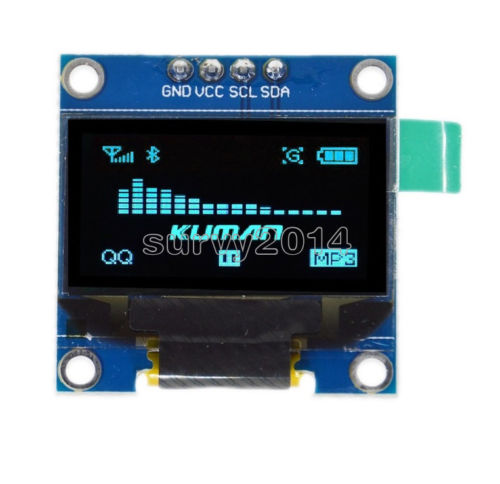
OLEDは0.96インチ,128*64, I2C接続の以下のものです。
Driver IC: SSD1306
0.96" I2C IIC Serial 128X64 128*64 Blue OLED LCD LED Display Module for Arduino | eBay
ライブラリ
ライブラリはadafruitのライブラリを使いました。
ライブラリマネージャ設定
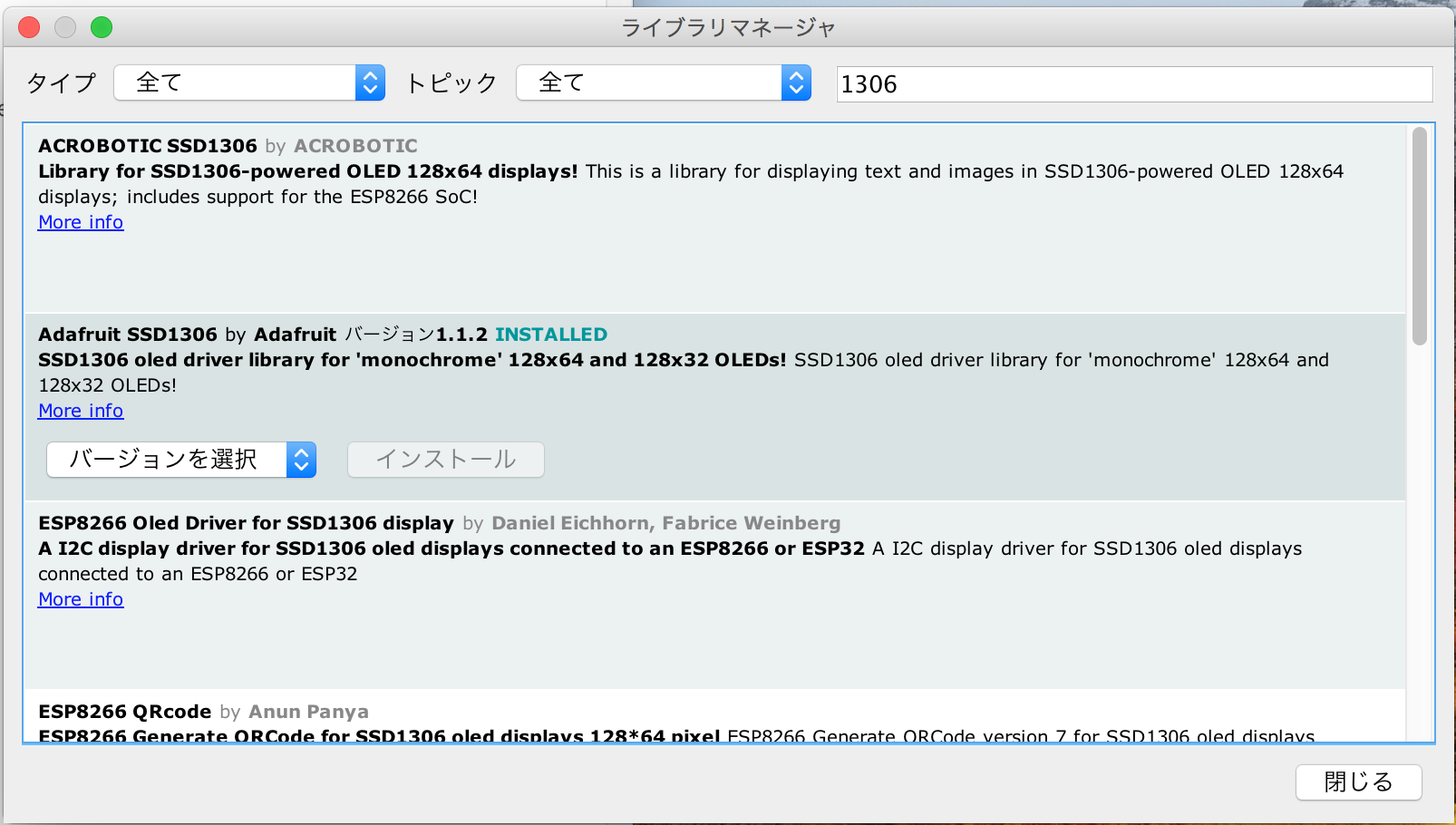
スケッチ>ライブラリをインクルード>ライブラリを管理
検索をフィルタに1306と入力し、フィルタリングされたAdafruit SSD1306 をインストールします。
サンプルスケッチ
ファイル>スケッチ例>Adafruit SSD1306 がメニューに追加されているので、候補の中からssd1306_128x64_i2c を選択します。
動作確認
ひとまず、マイコンボードに書き込むボタンを押してArudinoに書き込みます。
ここでOLEDの反応がなければ配線が間違っているか、I2Cアドレスが間違っているかだと思います。
以下の箇所でアドレスが0x3Dと指定されている箇所をOLEDのハードウェアの指定に合わせて変更してください。筆者の場合は0x3Cで動作しました。
display.begin(SSD1306_SWITCHCAPVCC, 0x3D); // initialize with the I2C addr 0x3D (for the 128x64)
よく分からなければ、i2c_scannerでアドレスをスキャンすると確実に分かると思います。
Arduino Playground - I2cScanner
動作画像
https://youtu.be/XH0BzGRPZRw
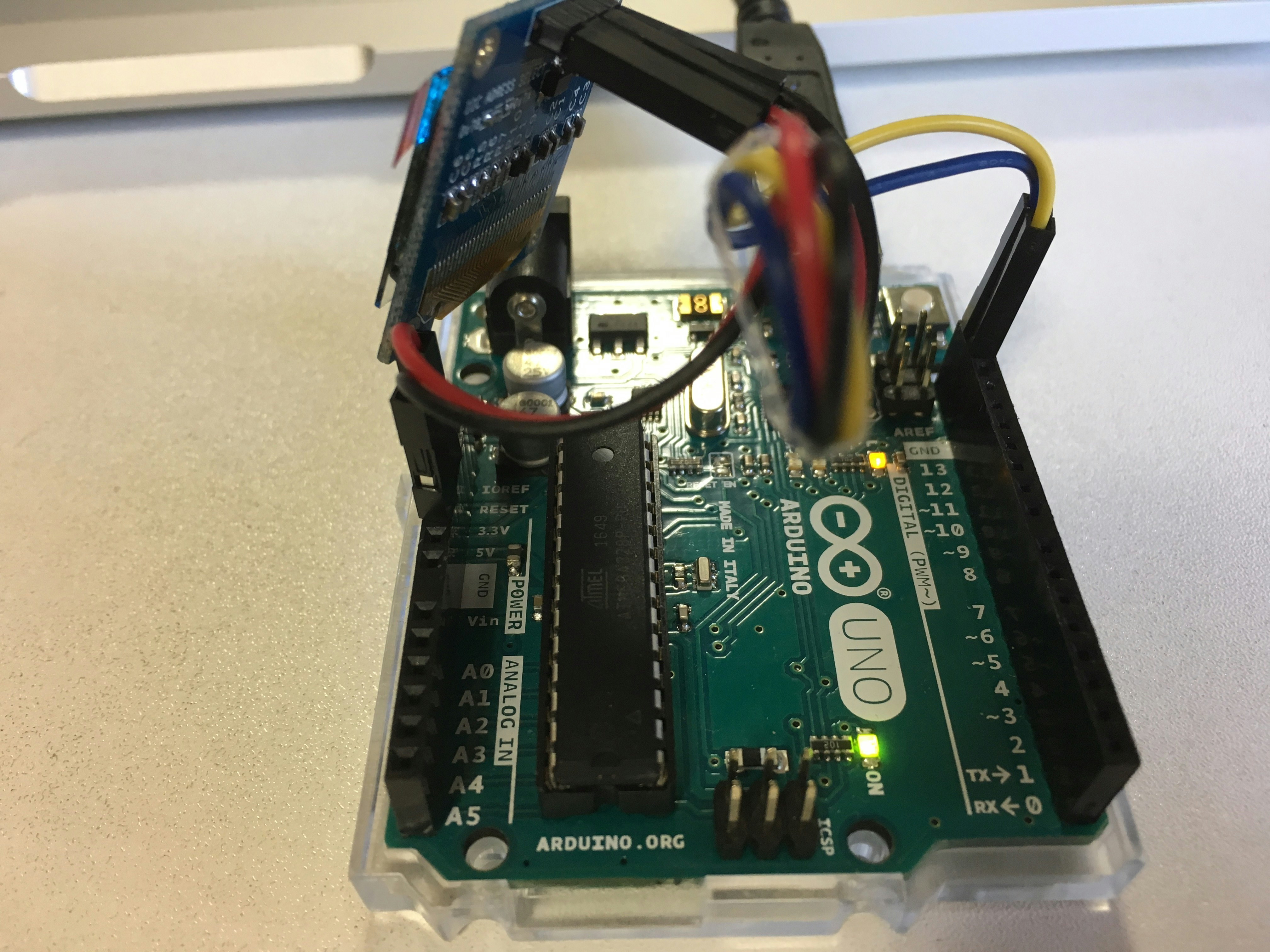
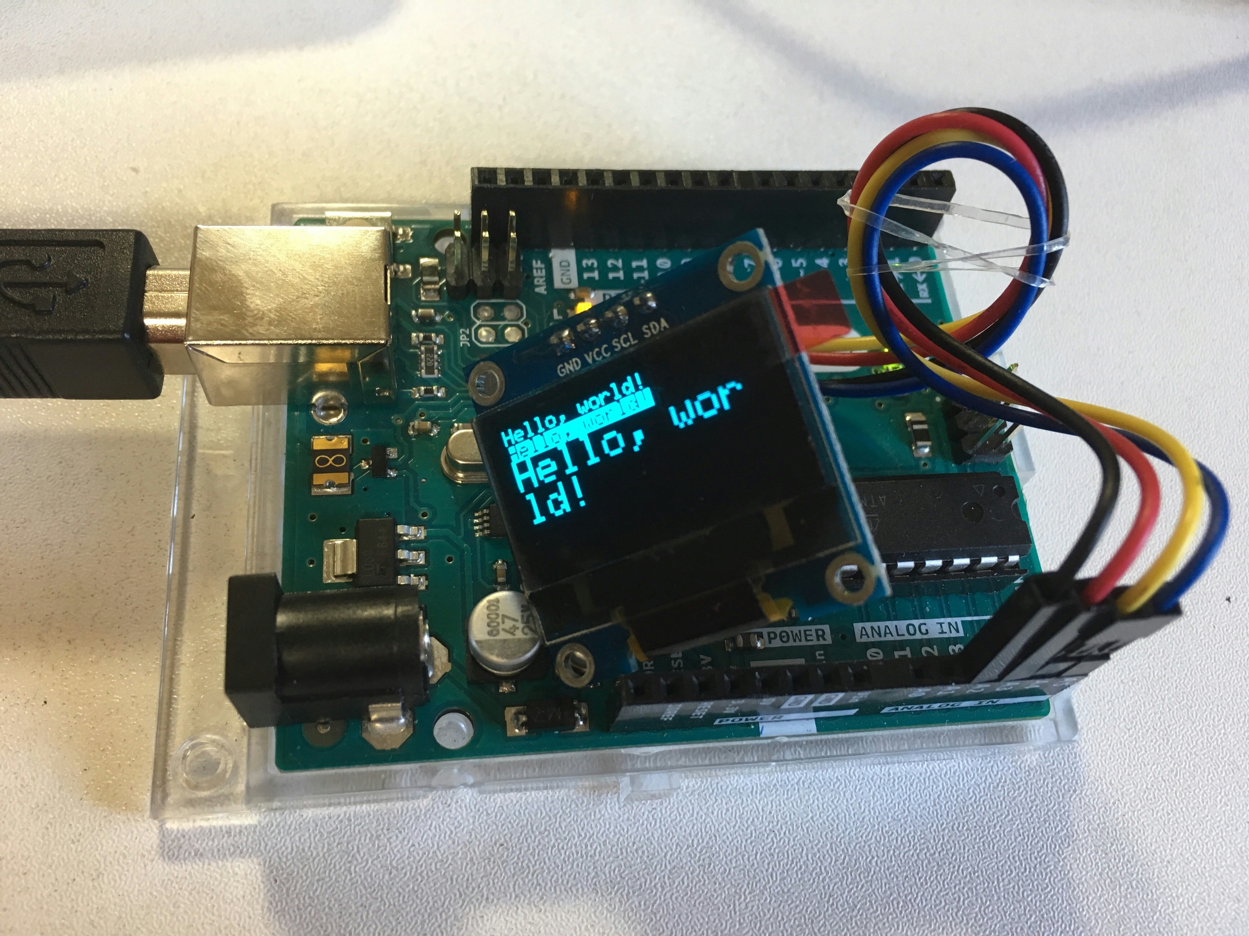
ArduinoとOLEDは以下のように配線しました。
| OLED | Arduino |
|---|---|
| GND | GND |
| VCC | 3.3v |
| SCL | SCL |
| SDA | SDA |
動作内容
初期化
以下の記述部でディスプレイの使用を開始&初期化します。
display.begin(SSD1306_SWITCHCAPVCC, 0x3C);
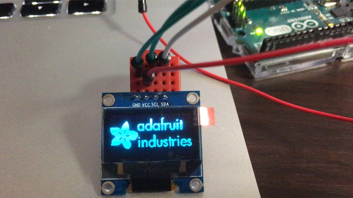
ここでAdafruitのロゴを表示する処理も入っているようです。
次の行でAdafruitのロゴが2秒表示されます。ロゴが必要なければ以下の処理を削除すればOKかと
display.display();
delay(2000);
このライブラリは以下の流れで画面へ描画するようです。
- display.clearDisplay()でバッファを空にする。
- drawPixelやprintlnで表示したい内容をバッファに書き込む。
- display.display();で画面を更新する。
- delay(2000); などで表示を保持する。
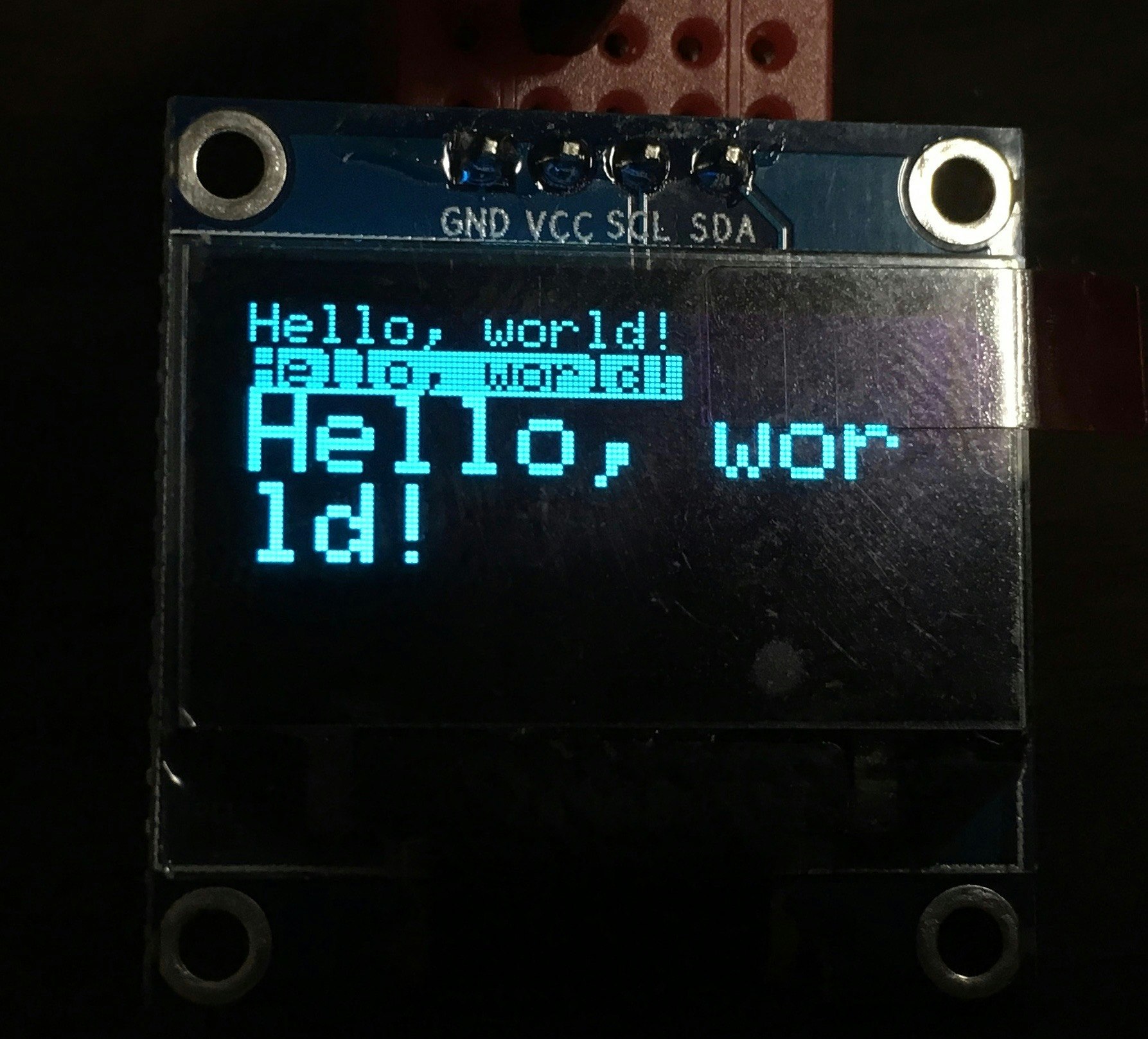
Hello world!のサンプルスケッチ
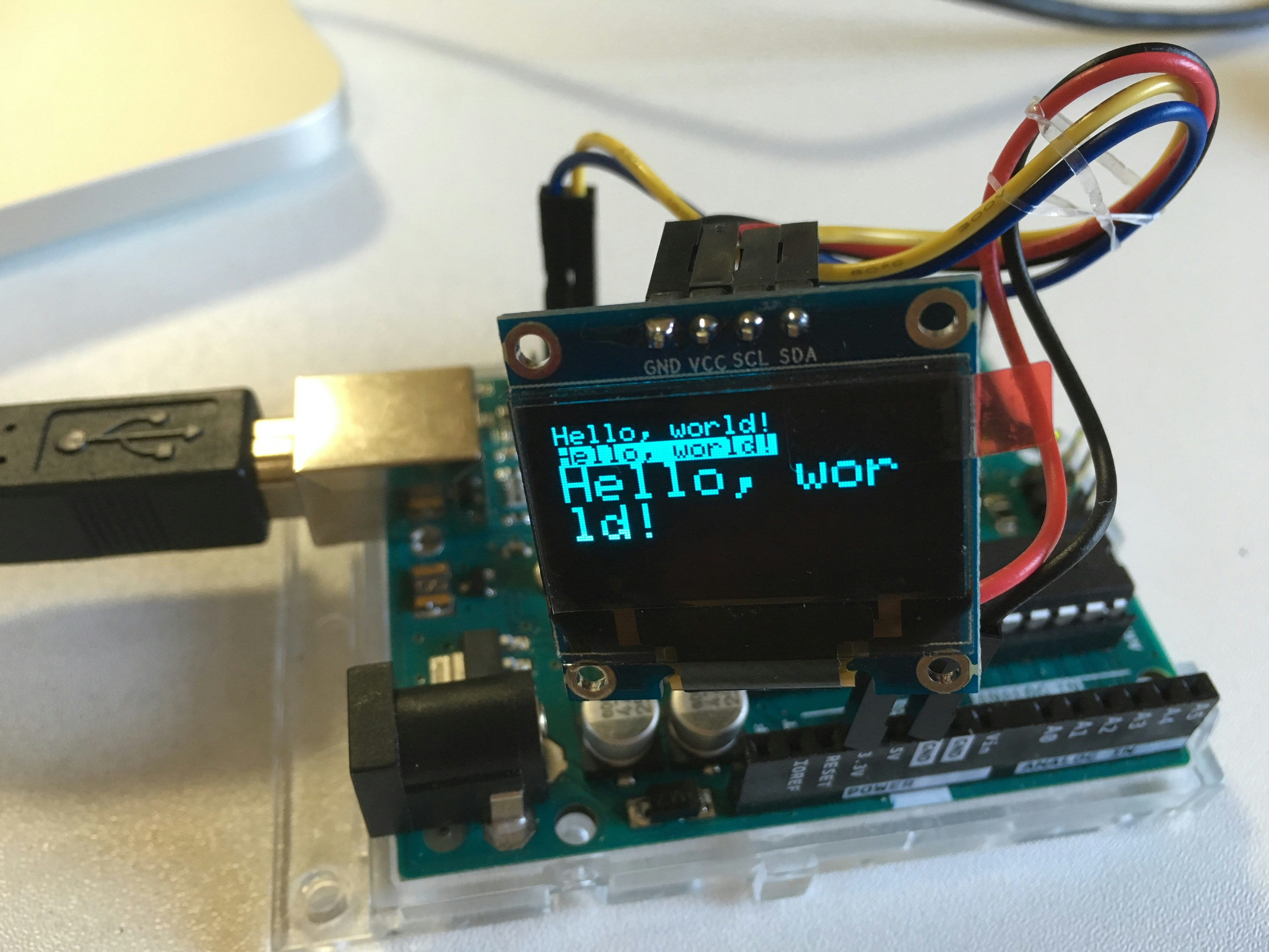
以下は1行目にテキストサイズ1でHello, world!を表示します。
2行目に背景色を黒(反転色)でHello, world!を表示
3行目にテキストサイズ2でHello, world!を表示します。
表示してから5秒後にディスプレイをクリアします。(表示消す)
# include <Wire.h>
# include <Adafruit_GFX.h>
# include <Adafruit_SSD1306.h>

# define OLED_RESET 4
Adafruit_SSD1306 display(OLED_RESET);

void setup()   {
  display.begin(SSD1306_SWITCHCAPVCC, 0x3C);  // initialize with the I2C addr 0x3D (for the 128x64)
  display.clearDisplay();

  // text display tests
  display.setTextSize(1);
  display.setTextColor(WHITE);
  display.setCursor(0,0);
  display.println("Hello, world!");

  display.setTextColor(BLACK, WHITE); // 'inverted' text
  display.println("Hello, world!");

  display.setTextSize(2);
  display.setTextColor(WHITE);
  display.println("Hello, world!");

  display.display();
  delay(5000);
  display.clearDisplay();
  display.display();
}


void loop() {

}
電源とGNDピン配置の変更
電源ピンを占有してしまうと使い勝手も悪い場合もあることから、ピン配置を変更してみます。
GNDをA2、VCCをA3
I2CではArduino UNOではD13の3つ隣にSCLとSDAピンがありますが、これはA4とA5ピンに内部的に繋がっているのでそれぞれA4、A5で代用できます。
ArduinoとOLEDは以下のように配線しました。
| OLED | Arduino |
|---|---|
| GND | A2 |
| VCC | A3 |
| SCL | A5 |
| SDA | A4 |
# include <Wire.h>
# include <Adafruit_GFX.h>
# include <Adafruit_SSD1306.h>

# define OLED_RESET 4
Adafruit_SSD1306 display(OLED_RESET);

# define gndPin A2    // ArduinoA2
# define vddPin A3    // ArduinoA3


void setup()   {
  pinMode(gndPin, OUTPUT);
  digitalWrite(gndPin, LOW);
  pinMode(vddPin, OUTPUT);
  digitalWrite(vddPin, HIGH);

  display.begin(SSD1306_SWITCHCAPVCC, 0x3C);  // initialize with the I2C addr 0x3D (for the 128x64)
  display.clearDisplay();

  // text display tests
  display.setTextSize(1);
  display.setTextColor(WHITE);
  display.setCursor(0,0);
  display.println("Hello, world!");

  display.setTextColor(BLACK, WHITE); // 'inverted' text
  display.println("Hello, world!");

  display.setTextSize(2);
  display.setTextColor(WHITE);
  display.println("Hello, world!");

  display.display();
  delay(5000);
  display.clearDisplay();
  display.display();
}


void loop() {

}
