はじめに
f401reは3つのUARTが使えるのですが、その内の1つが購入時の状態だと使えなかったので使えるようしました。
今回の記事ではPlatformIO IDE for VSCodeを使っていますが、記事の本題とはあまり関係ないです。
動作環境
今回の動作環境は
- Windows10
- PlatformIO IDE for VSCode
- STSTM32(ver4.4.0)
STSTM32はmbed対応のstm32bitマイコンをmbedで書くためのPlatformIOのプラットフォームの1つです。
配線
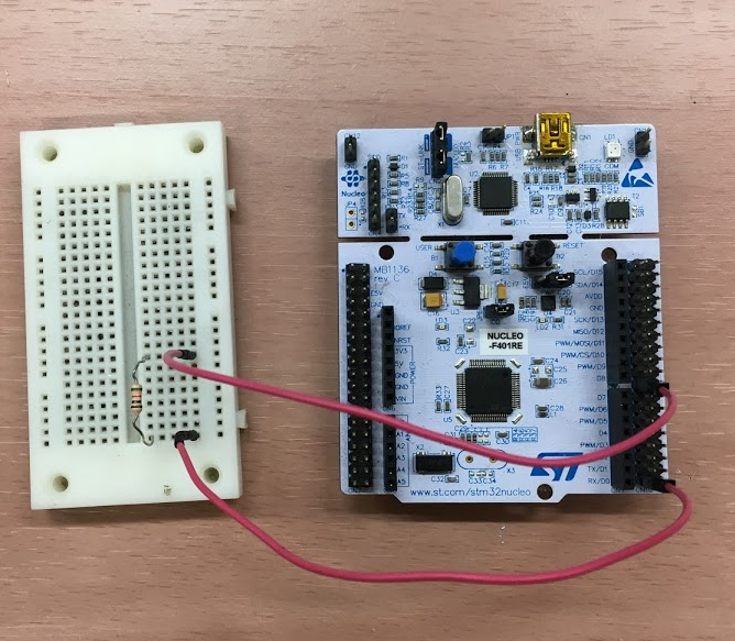
パソコンとMini USBをつなぐだけでf401reの電源が入るように、リセットボタンのすぐ下にあるジャンパをPWRがU5Vと繋がるように差し替えます。
一応抵抗を間に挟んでUART1のTXピン(PA_9)とUART2のRXピン(PA_3)をつなぎます。
(mbedで使うf401reのピン名の定義はこちらのmbedが出しているf401reの概要ページにあります)
テストプログラム
UART1のTXから適当な信号を送ってUART2で受け取ったらLチカするだけの簡単なプログラムです。
# include <mbed.h>

void Receiving();//受信時割り込み

Serial send(PA_9, PA_10, 19200);//(TX, RX, baud)
Serial receive(PA_2, PA_3, 19200);
DigitalOut userLED(PA_5);//LD2

int main() {
  userLED = 0;
  receive.attach(&Receiving,Serial::RxIrq);
  while(1) {
    send.putc('a');
    wait(0.5);
  }
}

void Receiving(){
  userLED =!userLED;//Lチカ
  receive.getc();//念のため
}
; PlatformIO Project Configuration File
;
;   Build options: build flags, source filter
;   Upload options: custom upload port, speed and extra flags
;   Library options: dependencies, extra library storages
;   Advanced options: extra scripting
;
; Please visit documentation for the other options and examples
; https://docs.platformio.org/page/projectconf.html

[env:nucleo_f401re]
platform = ststm32
board = nucleo_f401re
framework = mbed
本題
しかしこれだけではUART2を使うことはできません。
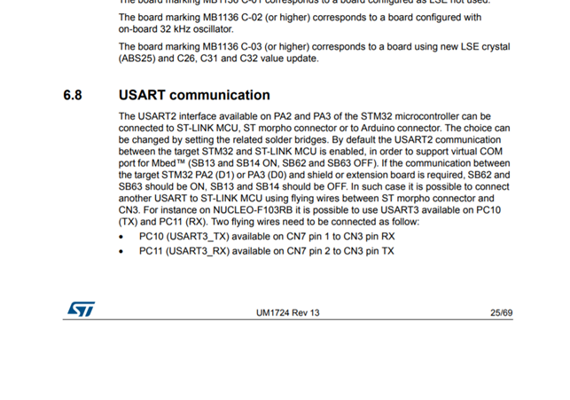
STMicroelectronicsが出しているユーザーマニュアルをみると、8.3 USART communicationに(この記事ではUARTとして使っていますが)、USART2はデフォルトではPA_2/PA_3には繋がっていなくて、代わりにSB13とSB14を介して仮想COMと繋がっているとあります。
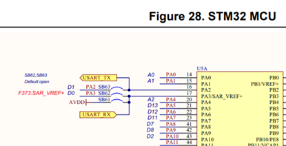
さらにページを進めると、それっぽい図も出てきます。
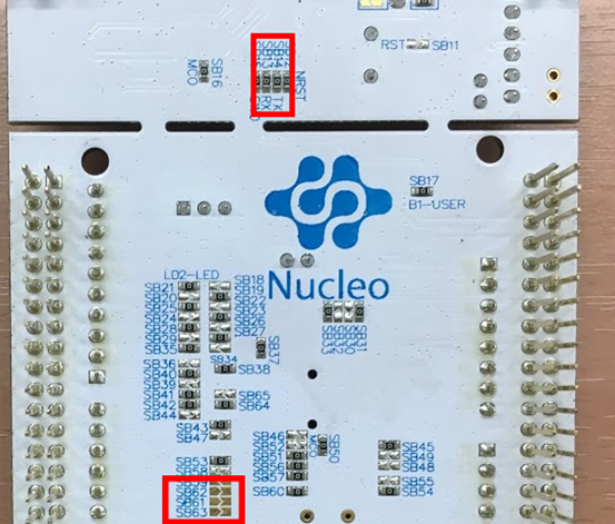
(下の画像のSB62/SB63の橋みたいなところを繋げたらつながりそう)
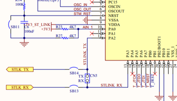
下の画像はFigure 29. ST-LINK/V2-1の一部です。PA2/PA3がSB14/SB13を介してSTLINKのTX/RXと繋がっています。
f401reの裏面の赤枠の部分、SB62/SB63を繋げてSB13/SB14の0Ω抵抗を外します。
.
.
.
できました。
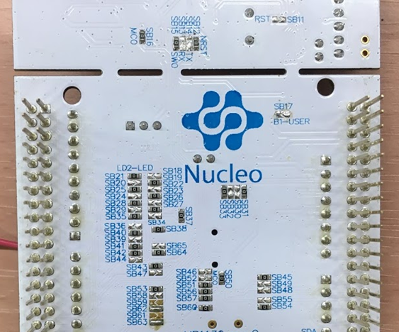
プログラムを実行すると、1秒周期でLチカしているのが確認できました。
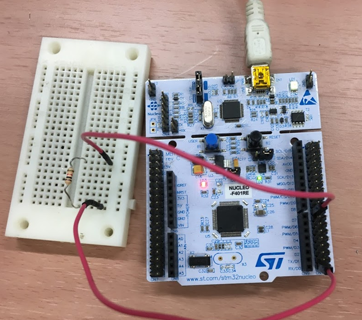
送るのをUART2に変えてもLチカできたので、TXRX共に正常に動いているようです。
まとめ
このピンの接続法(というかボードの設計)はMB1136をベースにした STM32 Nucleo-64マイコンで共通らしいのでnucleo f411reやその他のマイコンでも同様の作業を行う必要がある。
そしてこの作業をするとUSBTX/USBRXが使えなくなる(debug時とかにこの名前でSerialをつくればマイコンをパソコンと接続するだけでTera Termかなんかを使って通信できる)。
が、今回自分はその機能は必要なかったしまあいいかなと思う。
また、自分のメモ用にと思って初めてQiitaで記事を書いてみたが、それにあたって色々なサイトを調べてより理解が深まったので、また何かあれば記事を書いていこうと思う。