Introduction
This section uses the fastball as an example to explore the fundamentals of the ball rotation control mechanism before release. The fastball is the most natural way to throw a pitch, and the meaning of this “naturalness” will be clarified later in this series of articles.
Considering the mechanics of a rigid body as a spherical object, the ball is subject to forces and torques that induce rotation. In the previous chapter (1), we discussed the kinematics of rotation and the dynamics of translation. In contrast, this chapter outlines the fundamentals of the rotational dynamics of the ball as a rigid body. We introduce the points of application of forces, which can be calculated from the forces and torques, and we organize the basics to understand the physical meaning of the ball's behavior.
Review

Fig.1: Changes in the rotational behavior of the ball during pitching:
 an example of a fastball at approximately 130 km/h.
As described in the previous chapter, if we observe the angular velocity of the ball, which is depicted in magenta in Fig. 1, after the start of pitching, the ball rotates with topspin at low angular velocity conditions. Note, however, that rather than topspin being applied by the hand to the ball, the arm and the ball are “united” because the ball is held in the hand. The rotation of the arm is reflected in the angular velocity vector, which points to the
Then, about 15 ms before the release, the ball's rotation switches from topspin to backspin, which is the kinematic start of rotation. At the moment of this switch, the thumb starts to detach from the ball. This series of articles will describe whether this release is an active or passive phenomenon.
The torque that gives backspin to the ball begins to be applied approximately 5 ms before the start of the backspin, and backspin is initiated by stopping the forward momentum of the spin. In other words, the torque that causes backspin is initially used to ‘stop the topspin rotation’s momentum before the spin starts. The timing at which this torque is applied is referred to here as the dynamic start of rotation, and the time from there to the release is called the rotation control phase.
Note that the rotational force of the backspin is thus applied before the start of the backspin.
Mechanics of ball rotation
During the phase when the ball accelerates, backspin does not begin even if the thumb is removed. This occurs because the ball is subjected to a torque in the same direction as the topspin. To achieve backspin, a moment must be applied to t

Fig.2: Forces acting on the ball generate torque.
 (a) A force acting off the center of the ball causes it to rotate.
 (b) If the position vector of the contact point from the center is r,
 the magnitude of the torque acting on the ball is determined by the
 area of the parallelogram created by the vectors r and f. As in (b),
 the vector towards the back of the paper is denoted by x, viewed from
 the head side of the Phillips screw. The axis of rotation in the
 opposite direction, not shown here, is denoted by ⦿ viewed from the tip side.
A force $\boldsymbol{f}$ acts on the ball, generating torque to rotate it (Fig. 2). The torque can be applied to the ball in various ways during baseball pitching. In a fastball, the force exerted between the fingertips of the index and middle fingers primarily applies torque to the ball. The torque generated by a force about a specific point is called the moment of force. Here, the vector $\boldsymbol{r}$ corresponds to the lever, and the arrow's tip indicates where the force acts.
A force $\boldsymbol{f}$ acting off the center of the ball causes it to rotate (Fig. 2(b)). If the force is directed downward from the center, it generates backspin. The force must be deflected upward in the case of topspin, such as in a curve. Directing the force toward the center of the ball to prevent rotation is challenging; this is easily understood from the difficulty of throwing a knuckleball.
During pitching, surface contact occurs between the ball and the fingers, with a continuous distribution acting on the ball's surface. This sum of forces represents a single resultant force. The point where this resultant force acts is called the point of application of force. This is similar to the center of pressure (COP) but represents a different physical quantity.
The geometric meaning of the torque vector
Moments of force are described using the outer product of vectors
$$
\boldsymbol{r} \times \boldsymbol{f}.
$$

Fig.3: right-hand screw vector
In the previous example, just as a vector of arrows represents the angular velocity vector, moments of force (torque) are also depicted by a vector indicating the axis of rotation.
Direction of the torque vector
The torque vector is represented by the right-hand screw rule: the direction of the vector corresponds to the axis along which a right-handed screw advances, and the sense of rotation corresponds to the direction in which the screw turns (Fig. 3).
Magnitude of the torque vector
The magnitude of the vector representing rotational force is expressed in terms of length. The magnitude of the moment of force can be described by the area of the parallelogram formed by the force vector $\boldsymbol{a}$ and $\boldsymbol{b}$(Fig.4).
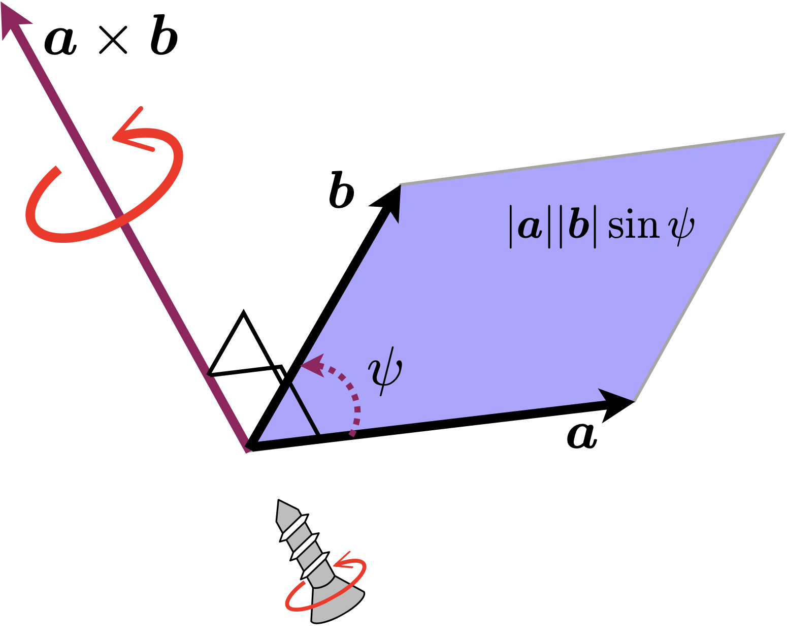
Fig.4: outer product a x b
Decomposition of torque as a screw
In the previous chapter, the forces acting on the ball were decomposed into forces acting in the direction of the velocity and a centripetal force.
Again, when considering ball dynamics, we must explore the physical meaning of decomposing the torque acting on the ball into two torques. This is essential for understanding the ball's behavior.
Moments of force generated by the forces acting on the ball
As already explained, in the case of fastballs, the moment of force (see Figure 2) created by the force exerted by a fingertip or similar in a single, roughly coherent area almost dominates the ball's rotational force.
If this is not surface contact but point contact, only $\boldsymbol{r} \times \boldsymbol{f}$ acts, as shown in Figure 2. However, in the case of surface contact, another moment is generated.
Torsional moment

Fig.5: (a) Torsional moment acting on the ball surface.
    (b) A torsional moment acts on a plane perpendicular to the force
    vector. The plane does not touch the sphere's surface; part of it
    is embedded in the interior.
When there is surface contact between the ball's surface and the fingers, forces are distributed and act in the contact area. The orange vectors in Fig. 5 (a) illustrate only the forces directed tangent to the plane. In other words, imagine a tangent plane that touches the sphere at the point of application. If this vector curls as depicted in Fig. 5 (a), it produces a total torsional moment, indicated by the black arrow.
Since there is always surface contact between the ball and the fingertips during pitching, this torsional moment around the axis of the force also influences the ball.
However, the other moment acting on the ball considered here is not the moment of the force acting on the tangent plane to the ball's surface. We now examine the projection of the force vector onto a plane perpendicular to the axis on which it acts (Fig. 5 (b)). Note that the orientation of this new plane (normal direction) differs from that of the surface's tangent plane. The finger never contacts such a plane, but the force distribution in contact with the ball's surface is projected onto this plane. The orange dashed forces in the projected plane of Fig. 5 (b) generate moments around the blue arrow (the direction of the axis is the same as that of the force $\boldsymbol{f}$), as shown in Fig. 5 (a). This is the torsional moment around the force vector $\boldsymbol{f}$.
In the previous chapter, the forces were decomposed into one acting in the direction of the velocity and a centripetal force, and their meanings were discussed. Again, it was demonstrated that the torque acting on the ball can be decomposed into a force moment created by the force acting on the ball and a torsional moment parallel to that force vector. I want to add that, in the case of surface contact, the torque acting on the ball cannot be described by the force moment $\boldsymbol{n}_f$ alone, but also by the $\boldsymbol{n}_t$ orthogonal to it.
Geometric relations between the vectors

Fig.6: F(a) Moment of force nf created by the force f acting on the ball;
 (b) moment of force nt created by friction, etc. The moment nf is
 created by the force acting on the ball is orthogonal to the force
 vector. Furthermore, the moment nf of the force and the moment nm
 created by friction are orthogonal. As a result, the moment created by
 the force acting on the ball and the moment developed by friction nt are parallel.
Here again, the vectors are organised by naming the appearing vectors.
- The force vector $\boldsymbol{f}$
- The moment of force created by the force vector $\boldsymbol{n}_f$
- The moment of torsion $\boldsymbol{n}_t$
Also,
-
The force vector $\boldsymbol{f}$ and the moment of force $\boldsymbol{n}_f$ it creates can be shown to be orthogonal, given the nature of the outer product (Figures 2 and 4).
-
The moment vector created by the force acting on the ball and the vector of the torsional moment are also orthogonal. It may be better to say that they are decomposed so that they are orthogonal
-
Furthermore, it can be seen that the force vector and the torsional moment vector are parallel, i.e., they point in the same direction. This means that
$~$
- $\boldsymbol{f} \perp \boldsymbol{n}_f$
- $\boldsymbol{n}_f \perp \boldsymbol{n}_t$
- $\boldsymbol{f} \parallel \boldsymbol{n}_t$
can be written as 1, 2, 3.
Note that this decomposition is similar to the moment generated by the ground reaction force and due to friction (free moment) in force plate dynamics. However, note that this is not the centre of pressure (COP).
COP is the position of the centre of pressure of the force acting in the direction normal to the tangent plane of the sphere, as shown in Fig. 5 (a). In contrast, the point of action of the force is the representative point of the force acting on the force vector, as shown in Fig. 5 (b), which has a different physical meaning. Both are representative values of the force, but the coordinate system considered is different, the method of deriving the point of application of force differs from COP, and the results vary.
Summary
The torque acting on the ball is decomposed into a moment of rotation $\boldsymbol{n}_f$ caused by the force $\boldsymbol{f}$ acting on the ball and a torsional moment $\boldsymbol{n}_t$ orthogonal to it, by introducing a point of application of force.
We considered forces and moments acting on rigid bodies and use this to introduce the mathematical notion of screw systems. A generalized force acting on a rigid body consists of a linear component (pure force$\boldsymbol{f}$) and an angular component (pure moment $\boldsymbol{n}_f$) acting at a point. We will refer to a force/moment pair as a wrench ($\boldsymbol{f} / \boldsymbol{n}_t$).
Future discussions will demonstrate that the dynamics of ball rotation can be better understood by considering the point of application of force as the location where the force is applied.