Oracle Cloud Infrastructure (OCI)サイト間VPNサービスは、オンプレミス・ネットワークとVirtual Cloud Network (VCN)間にセキュアなIPSec接続を提供します。サイト間VPNを使用して、Oracle Cloud Infrastructureリソースを他のクラウド・サービス・プロバイダに接続することもできます。
ということで、OCIサイトツーサイトVPNサービスおよびAWSサイトVPNサービスを使用したOCIとAWS間のIPSec VPNトンネルのベスト・プラクティス構成をしてみてみます。
■ 構成イメージ
このドキュメントでは、すでに OCI Virtual Cloud Network (VCN)および Amazon Virtual Private Cloud (VPC) をプロビジョニングしており、このシナリオに必要なすべての VCNルート表およびセキュリティ・リストとAWSの同等のものも構成済であることを前提としています。
■ AWSに固有の考慮事項
-
事前共有キー:
トンネルの事前共有キーを自動生成するためにAWSに依存している場合、生成されたキーにはピリオドまたはアンダースコア(.または_)文字が含まれている可能性があります。OCIでは、事前共有キーでこれらの文字はサポートされていません。AWSで自動生成されたパスワードにこれらの文字が含まれている場合は、VPN構成を完了する前に、関連するトンネル用の事前共有キーを変更します。 -
ルーティング・タイプ:
このシナリオでは、Border Gateway Protocol (BGP)を使用して、AWSとOCI間のルート交換を行います。可能な場合は常に、IPSecトンネルにBGPを使用してください。オプションで、AWSとOCI間に静的ルーティングを使用することもできます。
■ サポートされているIPSecパラメータ
すべてのOCIリージョンでサポートされているIPSecパラメータのリストは、サポートされているIPSecパラメータを参照してください。
■ 構成プロセス
![]() AWS - 一時カスタマ・ゲートウェイの作成
AWS - 一時カスタマ・ゲートウェイの作成
![]() AWS - 仮想プライベートゲートウェイの作成およびアタッチ
AWS - 仮想プライベートゲートウェイの作成およびアタッチ
![]() AWS - VPN接続の作成
AWS - VPN接続の作成
![]() AWS - 構成のダウンロードと確認
AWS - 構成のダウンロードと確認
![]() OCI - CPEオブジェクトの作成
OCI - CPEオブジェクトの作成
![]() OCI - DRGの作成およびアタッチ
OCI - DRGの作成およびアタッチ
![]() OCI - IPSec接続の作成
OCI - IPSec接続の作成
![]() AWS - 新規カスタマ・ゲートウェイの作成
AWS - 新規カスタマ・ゲートウェイの作成
![]() AWS - 新規カスタマ・ゲートウェイのVPN接続の変更
AWS - 新規カスタマ・ゲートウェイのVPN接続の変更
![]() Site-to-Site VPN稼働確認
Site-to-Site VPN稼働確認
![]() OCI-AWSインスタンス間接続確認
OCI-AWSインスタンス間接続確認
![]() トラブルシューティング
トラブルシューティング
![]() 参考
参考
● AWS - 一時カスタマ・ゲートウェイの作成
構成プロセスの最初のステップは、一時カスタマ・ゲートウェイを作成することです。
この一時カスタマ・ゲートウェイは、AWSサイト間VPNを初期プロビジョニングして、トンネルのAWS VPNエンドポイントを公開するために使用されます。
OCIでは、IPSec接続を作成する前に、リモートVPNピアのパブリックIPが必要です。
このプロセスが完了すると、実際のOCI VPNエンドポイント・パブリックIPを表す新しいカスタマ・ゲートウェイが構成されます。
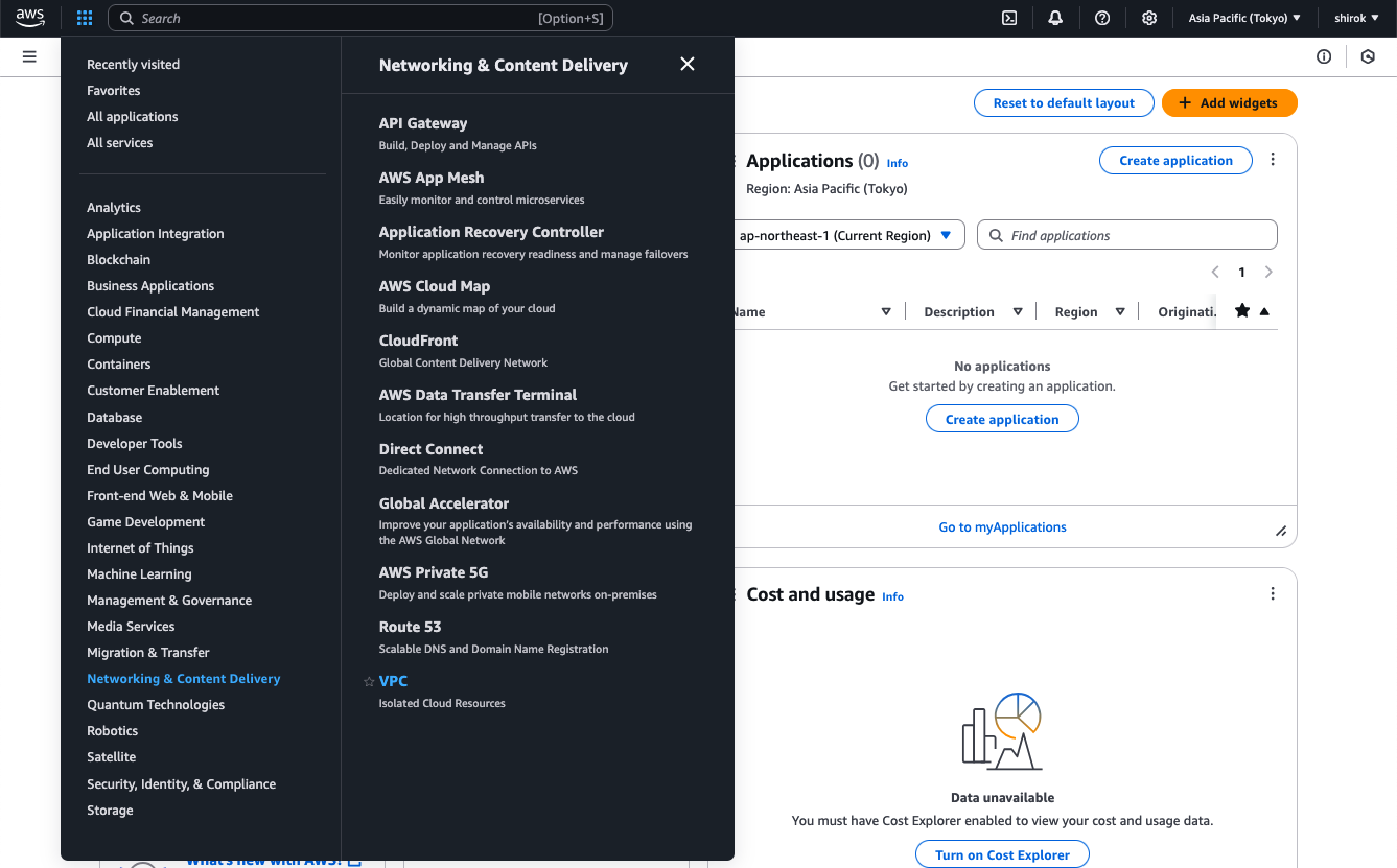
1) Amazon コンソール画面
メインの AWSポータルで、画面の左上にある[Services]メニューを展開し、[ネットワークおよびコンテンツ配信]の下の[VPC]をクリック
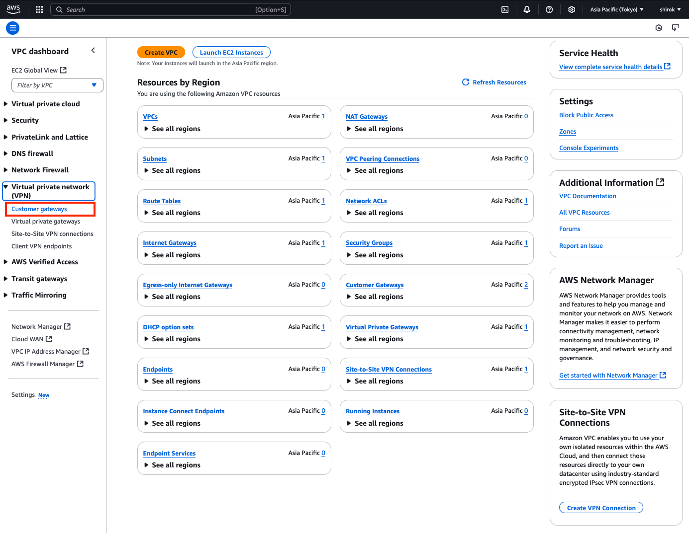
2) VPC 画面
左側のメニューで、下にスクロールして[Virtual Private Network (VPN)]の下の[Customer Gateway]をクリックします。
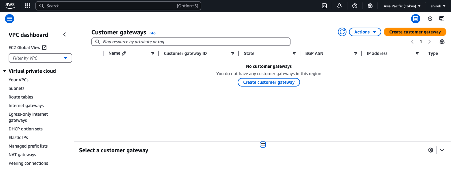
3) Customer gateway 画面
[ゲートウェイの作成]をクリックして、ゲートウェイを作成します。
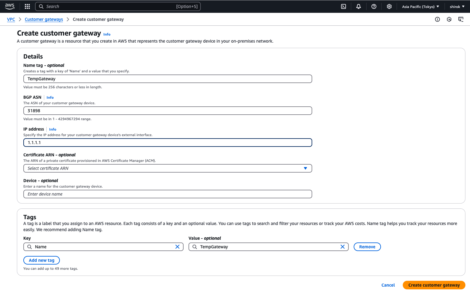
4) Create customer gateway 画面
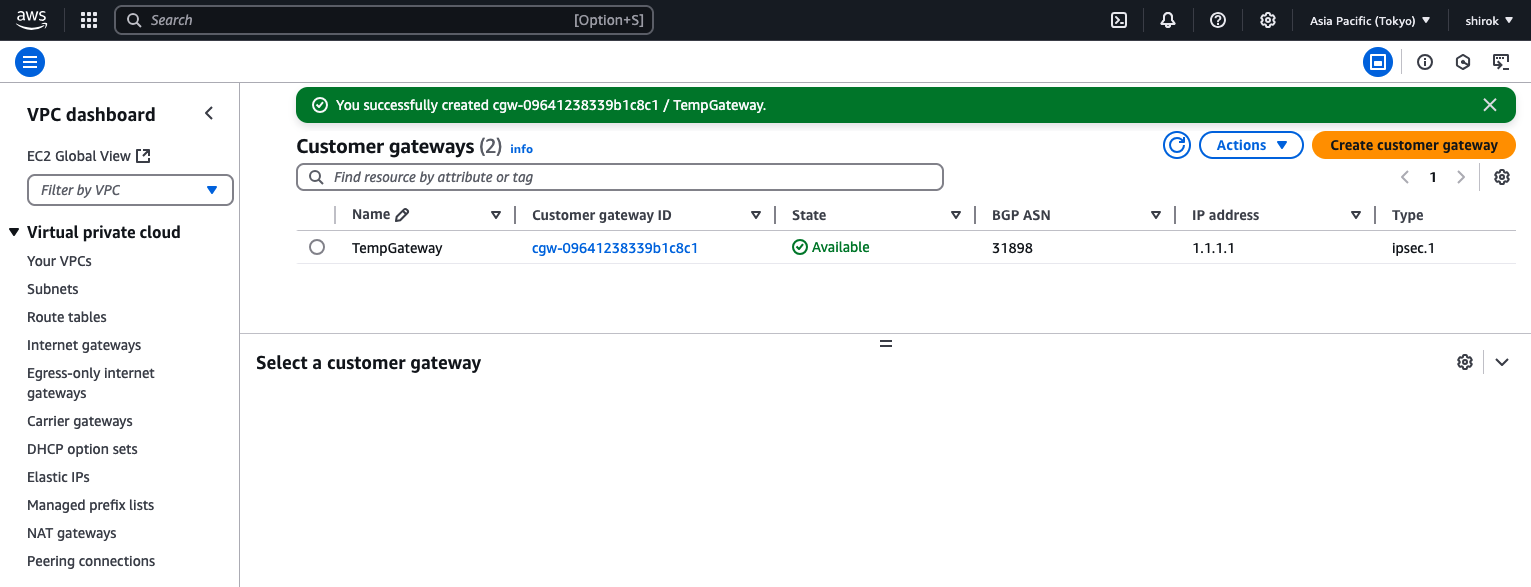
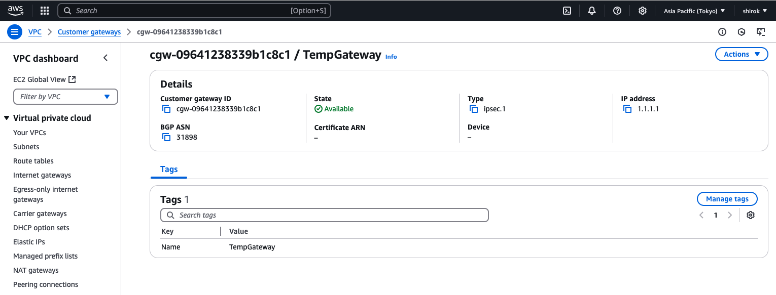
次の詳細を入力し、[Create Customer Gateway] をクリックしてプロビジョニング
・ Name:このカスタマ・ゲートウェイに一時的であることが明らかにします。この例では、TempGatewayという名前を使用します。
・ BGP ASN: OCI BGP ASNを入力します。Oracleの商用クラウド用のBGP ASNは31898です。
・ IP Address:一時ゲートウェイに任意の有効なIPv4アドレスを使用します。この例では、1.1.1.1を使用します。
● AWS - 仮想プライベート・ゲートウェイの作成およびアタッチ
1) Amazon コンソール画面
AWSの左側のメニューで、下にスクロールして[Virtual Private Network (VPN)]の下の[Virtual Private Gateways]をクリックします。
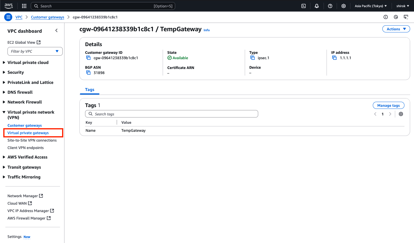
2) Virtual private gateways 画面
[Create Virtual Private Gateway]ボタンをクリックして、新しい仮想プライベートゲートウェイを作成します。

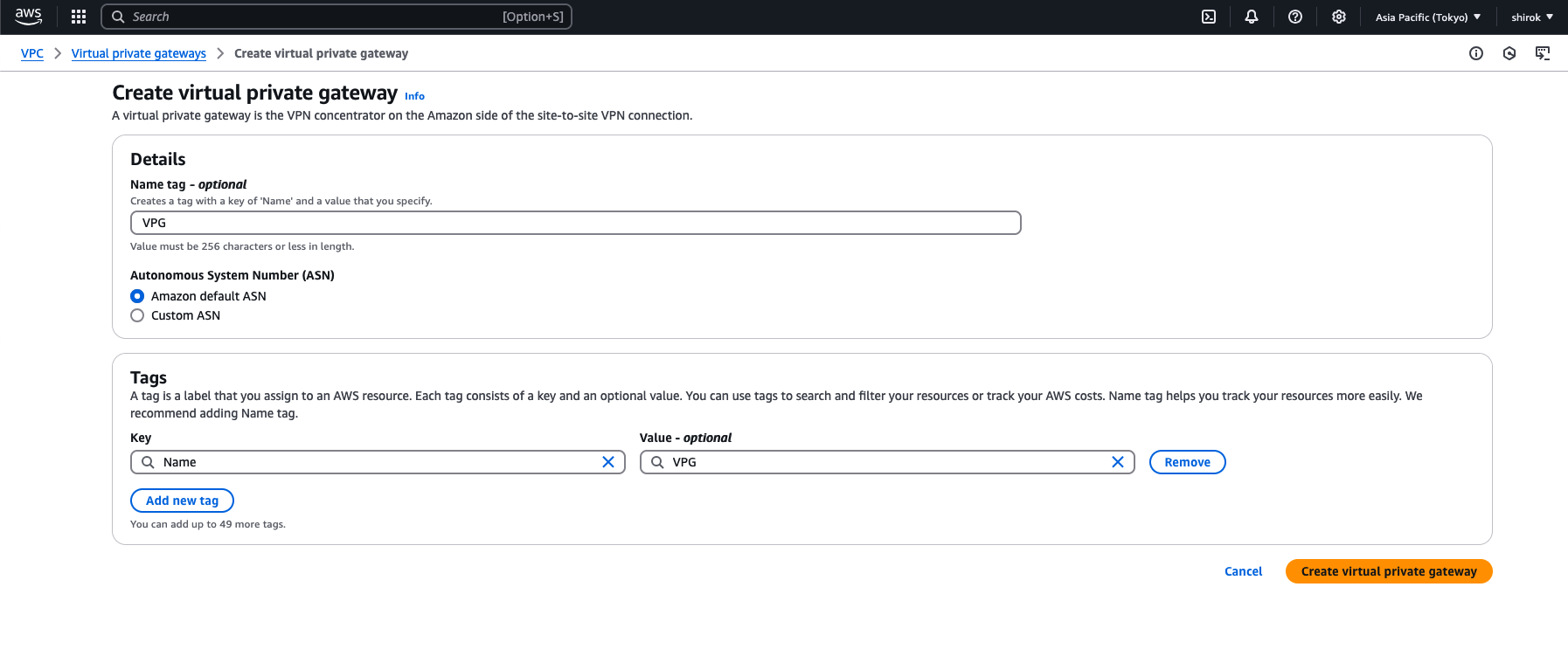
3) Create Virtual private gateway 画面
次の項目を入力し[Create VPN connection]をクリックしてプロビジョニングします。
・ Name: 仮想プライベート・ゲートウェイ(VPG)に名前を付けます。
・ ASN:  [Amazon default ASN] を選択します。
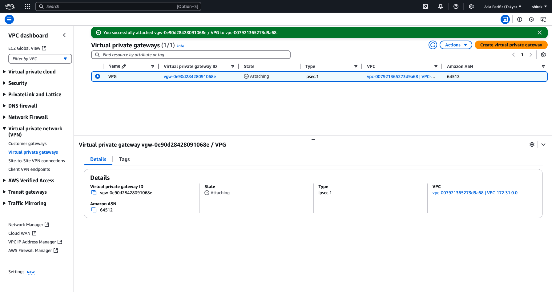
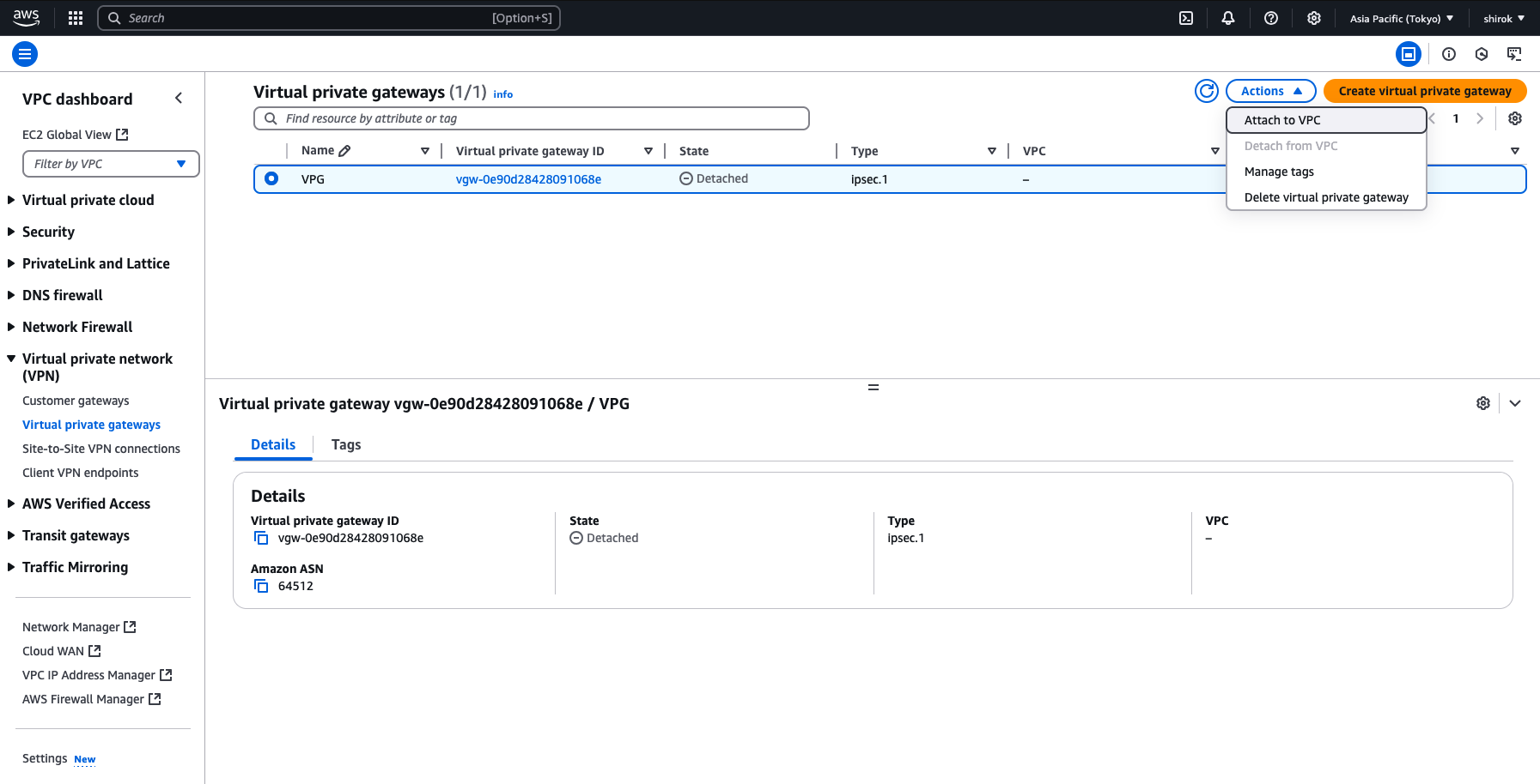
4) Virtual private gateways 画面
VPGの作成後、選択したVPCにVPGをアタッチする必要があります。
[Virtual Private Gateway]ページを表示したまま、VPGを選択し、[Actions]メニュー(アクション・メニュー)、[Attach to VPC]の順にクリック
5) Attach to VPC 画面
リストからVPCを選択し、[Attach to VPC]ボタンをクリックし、VPG を VPCへアタッチ

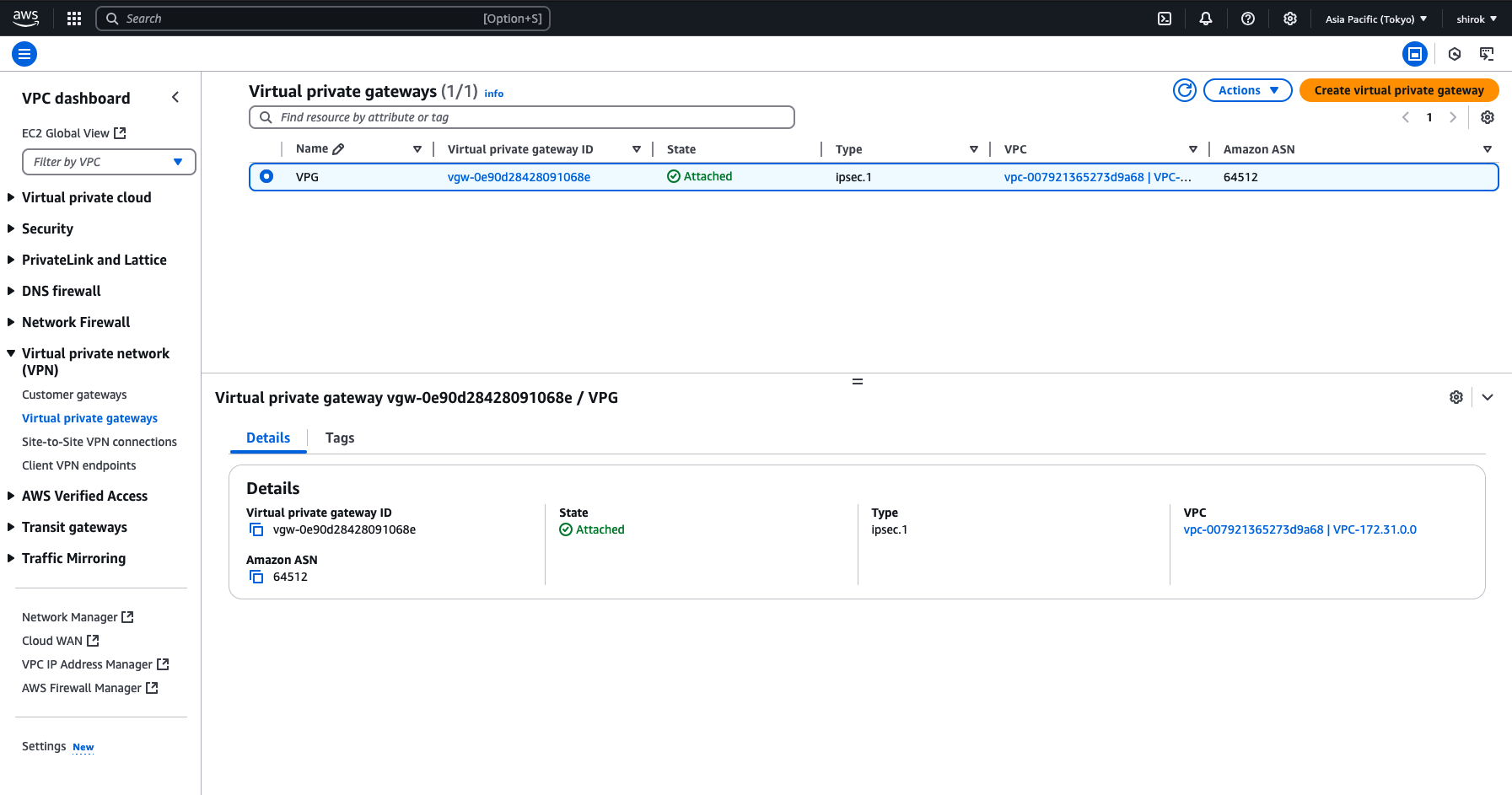
7) Attach to VPC 完了
State が Attached になれば完了
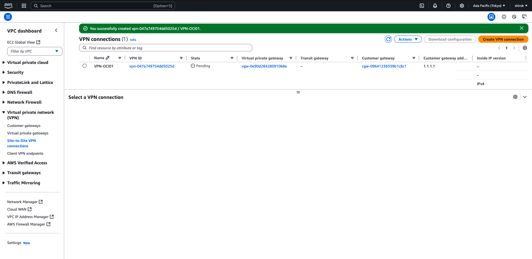
● AWS - VPN接続の作成
1) Amazon コンソール 画面
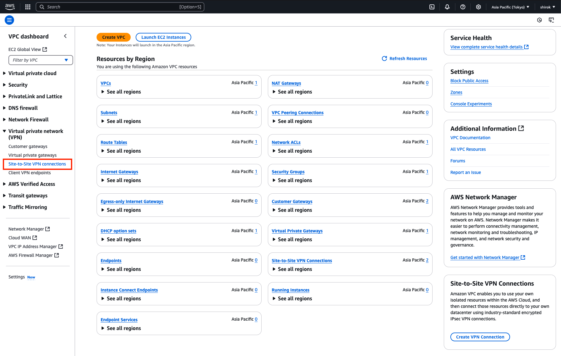
左側のメニューで、下にスクロールして[Virtual Private Network (VPN)]の下の[Site-to-Site VPN Connections]をクリック
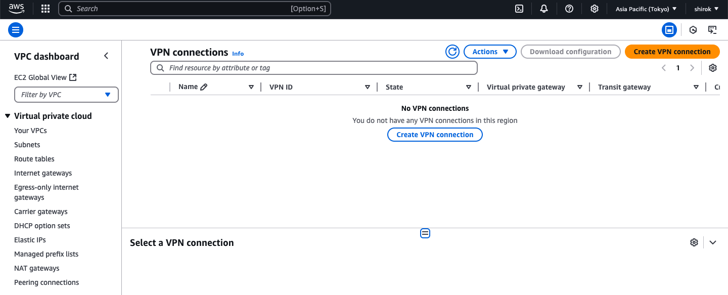
2) VPN connections 画面
[Create VPN Connection] をクリック
3) Create VPN connection 画面
OCIでサポートされているIPSecパラメータを参照して設定します。
[Create VPN Connection]ページが表示されます。次の詳細を入力し、必要なすべてのオプションの構成が終了したら、下部にある [Create VPN Connection] ボタンをクリックし、VPN接続をプロビジョニングします。
・ Details 項目
    ・ Name tag: VPN接続に名前を設定
    ・ ターゲット・ゲートウェイ・タイプ: [仮想プライベート・ゲートウェイを選択し、リストから以前に作成した仮想プライベート・ゲートウェイを選択
    ・ Customer Gateway: [Existing] を選択し、リストから以前に作成した一時カスタマ・ゲートウェイを選択
    ・ ルーティング・オプション: [動的(BGPが必要)] を選択
    ・ Tunnel Inside Ip Version: [IPv4] を選択
    ・ Local/Remote IPv4 Network Cidr:これらの両方のフィールドを空白のままにして、デフォルト: 0.0.0.0/0 の any/anyのルートベース IPSec VPNを作成

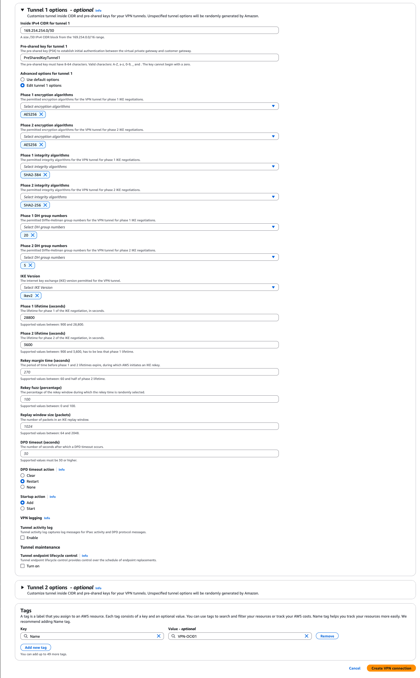
・ Tunnel 1 options - optional 項目
    ・ Inside IPv4 CIDR for tunnel 1: リンク・ローカルIP 169.254.0.0/16 の範囲内から /30 CIDR を設定
        ただし、OCIでは、トンネル内IPに次のIP範囲を使用できません: OCIが、トンネル内IPに対して選択した/30アドレスをサポートしていることを確認します。
        169.254.10.0 - 169.254.19.255
        169.254.100.0 - 169.254.109.255
        169.254.192.0 - 169.254.201.255
    ・ Advanced options for tunnel 1: [Edit Tunnel 1 Options]のラジオ・ボタンを選択します。追加のオプション・セットが展開されます。
     このトンネルに使用される暗号化アルゴリズムに制限が必要な場合は、必要なフェーズ1およびフェーズ2のオプションをここで構成します。
    Oracleでは、この接続にIKEv2を使用することをお薦めします。IKEv1が使用されないようにするには、[IKEv1]チェック・ボックスの選択を解除します。
    OCIでサポートされているフェーズ1およびフェーズ2のオプションを参照するには、[サポートされているIPSecパラメータ](https://docs.oracle.com/ja-jp/iaas/Content/Network/Reference/supportedIPsecparams.htm#ariaid-title**2)を参照してください。
    ここでは、次を設定
    ・ Phase 1 encryption algorithms: AES256
    ・ Phase 2 encryption algorithms: AES256
    ・ Phase 1 integrity algorithms: SHA2-384
    ・ Phase 2 integrity algorithms: SHA2-256
    ・ Phase 1 DH group numbers: 20
    ・ Phase 2 DH group numbers: 5
    ・ IKE Version: ikev2
    ・ Phase 1 lifetime (seconds): 28800
    ・ Phase 2 lifetime (seconds): 3600
    ・ DPD timeout action: restart
・ Tunnel 2 options - optional 項目
利用しないため、そのままにします。
● AWS - 構成のダウンロードと確認
・ 構成のダウンロード
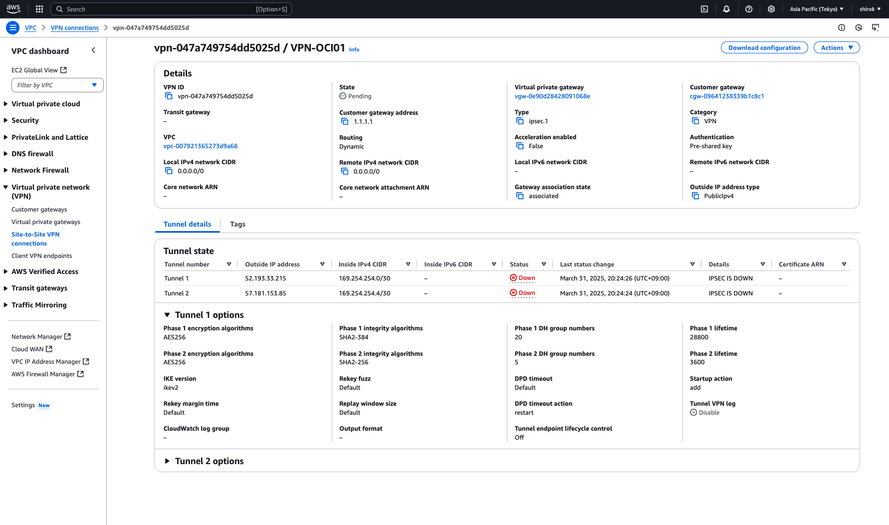
VPN接続のプロビジョニング中に、すべてのトンネル情報の構成をダウンロードします。このテキスト・ファイルは、OCIコンソールでトンネルの構成を完了するために必要です。
1) 作成した VPN Connection 画面
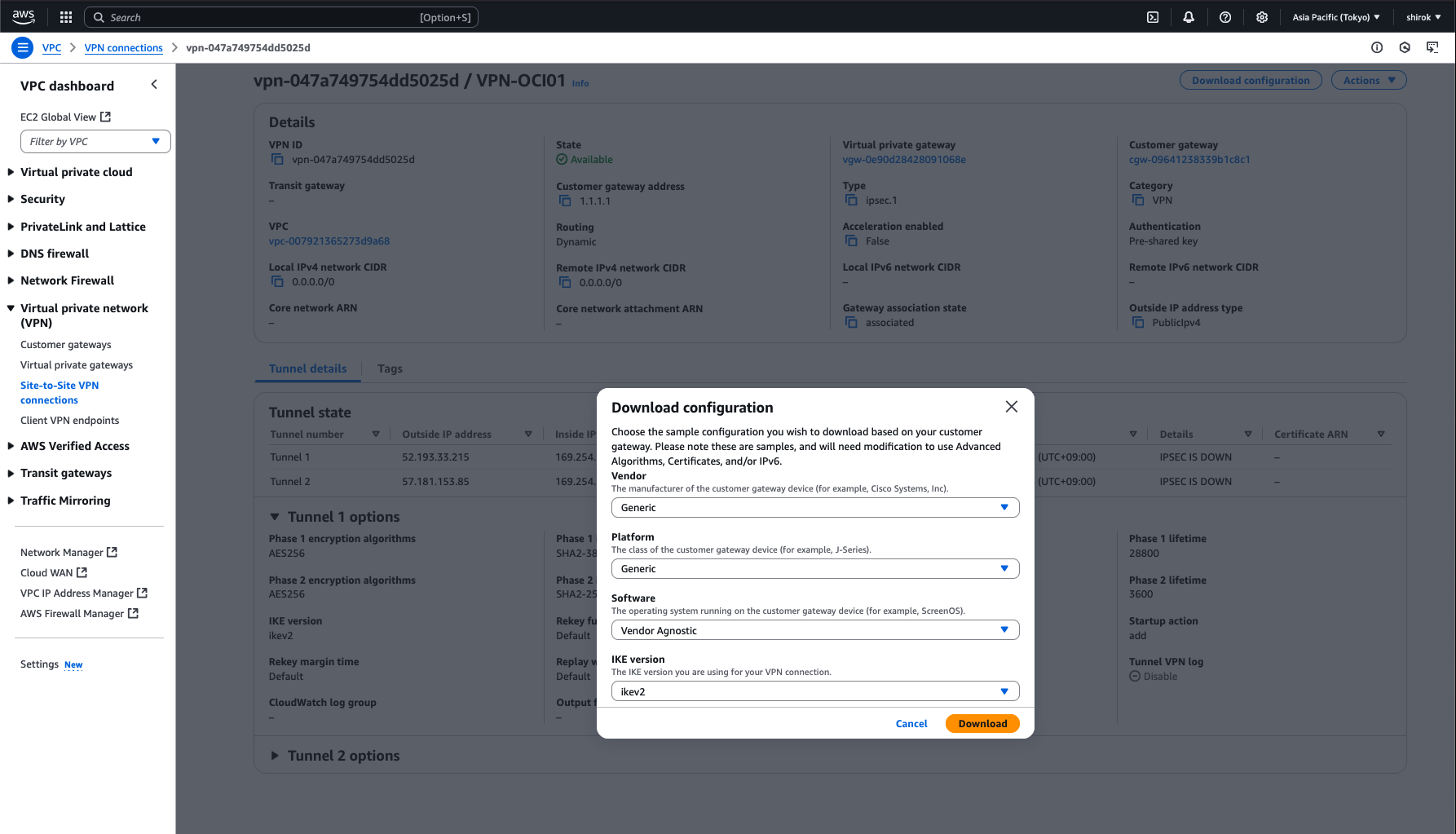
VPN接続が選択されていることを確認し、[Download Configuration]ボタンをクリック
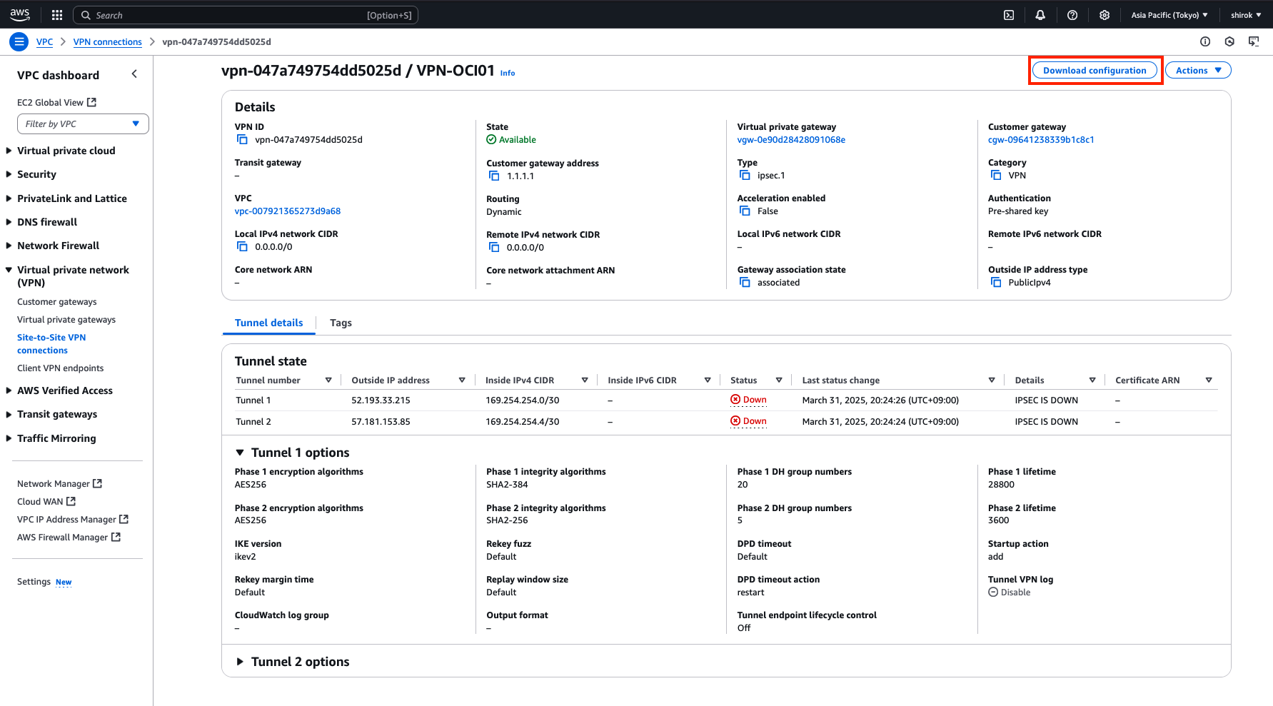
2) Download configuration 画面
次の項目を設定し、[Download] ボタンをクリックして、構成のテキスト・コピーをローカル・ハード・ドライブに保存します。
・ Vendor: Generic を選択
・ Generic: Generic を選択
・ IKE version: ikev2 を選択
3) Downloadファイル確認
Downpload Configurationファイル(vpn-id.txt)*クリックすると文章が展開されます。
Amazon Web Services
Virtual Private Cloud
VPN Connection Configuration
AWS utilizes unique identifiers to manipulate the configuration of
a VPN Connection. Each VPN Connection is assigned a VPN Connection Identifier
and is associated with two other identifiers, namely the
Customer Gateway Identifier and the Virtual Private Gateway Identifier.
Your VPN Connection ID : vpn-047a749754dd5025d
Your Virtual Private Gateway ID : vgw-0e90d28428091068e
Your Customer Gateway ID : cgw-09641238339b1c8c1
A VPN Connection consists of a pair of IPSec tunnel security associations (SAs).
It is important that both tunnel security associations be configured.
IPSec Tunnel #1
#1: Internet Key Exchange Configuration
Configure the IKE SA as follows:
Please note, these sample configurations are for the minimum requirement of AES128, SHA1, and DH Group 2.
Category "VPN" connections in the GovCloud region have a minimum requirement of AES128, SHA2, and DH Group 14.
You will need to modify these sample configuration files to take advantage of AES256, SHA256, or other DH groups like 2, 14-18, 22, 23, and 24.
NOTE: If you customized tunnel options when creating or modifying your VPN connection, you may need to modify these sample configurations to match the custom settings for your tunnels.
Higher parameters are only available for VPNs of category "VPN," and not for "VPN-Classic".
The address of the external interface for your customer gateway must be a static address.
Your customer gateway may reside behind a device performing network address translation (NAT).
To ensure that NAT traversal (NAT-T) can function, you must adjust your firewall !rules to unblock UDP port 4500.
If not behind NAT, and you are not using an Accelerated VPN, we recommend disabling NAT-T. If you are using an Accelerated VPN, make sure that NAT-T is enabled.
- IKE version : IKEv2
- Authentication Method : Pre-Shared Key
- Pre-Shared Key : PreSharedKeyTunnel1
- Authentication Algorithm : sha1
- Encryption Algorithm : aes-128-cbc
- Lifetime : 28800 seconds
- Phase 1 Negotiation Mode : main
- Diffie-Hellman : Group 2
#2: IPSec Configuration
Configure the IPSec SA as follows:
Category "VPN" connections in the GovCloud region have a minimum requirement of AES128, SHA2, and DH Group 14.
Please note, you may use these additionally supported IPSec parameters for encryption like AES256 and other DH groups like 2, 5, 14-18, 22, 23, and 24.
NOTE: If you customized tunnel options when creating or modifying your VPN connection, you may need to modify these sample configurations to match the custom settings for your tunnels.
Higher parameters are only available for VPNs of category "VPN," and not for "VPN-Classic".
- Protocol : esp
- Authentication Algorithm : hmac-sha1-96
- Encryption Algorithm : aes-128-cbc
- Lifetime : 3600 seconds
- Mode : tunnel
- Perfect Forward Secrecy : Diffie-Hellman Group 2
IPSec Dead Peer Detection (DPD) will be enabled on the AWS Endpoint. We
recommend configuring DPD on your endpoint as follows:
- DPD Interval : 10
- DPD Retries : 3
IPSec ESP (Encapsulating Security Payload) inserts additional
headers to transmit packets. These headers require additional space,
which reduces the amount of space available to transmit application data.
To limit the impact of this behavior, we recommend the following
configuration on your Customer Gateway:
- TCP MSS Adjustment : 1379 bytes
- Clear Don't Fragment Bit : enabled
- Fragmentation : Before encryption
#3: Tunnel Interface Configuration
Your Customer Gateway must be configured with a tunnel interface that is
associated with the IPSec tunnel. All traffic transmitted to the tunnel
interface is encrypted and transmitted to the Virtual Private Gateway.
The Customer Gateway and Virtual Private Gateway each have two addresses that relate
to this IPSec tunnel. Each contains an outside address, upon which encrypted
traffic is exchanged. Each also contain an inside address associated with
the tunnel interface.
The Customer Gateway outside IP address was provided when the Customer Gateway
was created. Changing the IP address requires the creation of a new
Customer Gateway.
The Customer Gateway inside IP address should be configured on your tunnel
interface.
Outside IP Addresses:
- Customer Gateway : 1.1.1.1
- Virtual Private Gateway : 52.193.33.215
Inside IP Addresses
- Customer Gateway : 169.254.254.2/30
- Virtual Private Gateway : 169.254.254.1/30
Configure your tunnel to fragment at the optimal size:
- Tunnel interface MTU : 1436 bytes
#4: Border Gateway Protocol (BGP) Configuration:
The Border Gateway Protocol (BGPv**4) is used within the tunnel, between the inside
IP addresses, to exchange routes from the VPC to your home network. Each
BGP router has an Autonomous System Number (ASN). Your ASN was provided
to AWS when the Customer Gateway was created.
BGP Configuration Options:
- Customer Gateway ASN : 31898
- Virtual Private Gateway ASN : 64512
- Neighbor IP Address : 169.254.254.1
- Neighbor Hold Time : 30
Configure BGP to announce routes to the Virtual Private Gateway. The gateway
will announce prefixes to your customer gateway based upon the prefix you
assigned to the VPC at creation time.
IPSec Tunnel #2
#1: Internet Key Exchange Configuration
Configure the IKE SA as follows:
Please note, these sample configurations are for the minimum requirement of AES128, SHA1, and DH Group 2.
Category "VPN" connections in the GovCloud region have a minimum requirement of AES128, SHA2, and DH Group 14.
You will need to modify these sample configuration files to take advantage of AES256, SHA256, or other DH groups like 2, 14-18, 22, 23, and 24.
NOTE: If you customized tunnel options when creating or modifying your VPN connection, you may need to modify these sample configurations to match the custom settings for your tunnels.
Higher parameters are only available for VPNs of category "VPN," and not for "VPN-Classic".
The address of the external interface for your customer gateway must be a static address.
Your customer gateway may reside behind a device performing network address translation (NAT).
To ensure that NAT traversal (NAT-T) can function, you must adjust your firewall !rules to unblock UDP port 4500.
If not behind NAT, and you are not using an Accelerated VPN, we recommend disabling NAT-T. If you are using an Accelerated VPN, make sure that NAT-T is enabled.
- IKE version : IKEv2
- Authentication Method : Pre-Shared Key
- Pre-Shared Key : PreSharedKeyTunnel2
- Authentication Algorithm : sha1
- Encryption Algorithm : aes-128-cbc
- Lifetime : 28800 seconds
- Phase 1 Negotiation Mode : main
- Diffie-Hellman : Group 2
#2: IPSec Configuration
Configure the IPSec SA as follows:
Category "VPN" connections in the GovCloud region have a minimum requirement of AES128, SHA2, and DH Group 14.
Please note, you may use these additionally supported IPSec parameters for encryption like AES256 and other DH groups like 2, 5, 14-18, 22, 23, and 24.
NOTE: If you customized tunnel options when creating or modifying your VPN connection, you may need to modify these sample configurations to match the custom settings for your tunnels.
Higher parameters are only available for VPNs of category "VPN," and not for "VPN-Classic".
- Protocol : esp
- Authentication Algorithm : hmac-sha1-96
- Encryption Algorithm : aes-128-cbc
- Lifetime : 3600 seconds
- Mode : tunnel
- Perfect Forward Secrecy : Diffie-Hellman Group 2
IPSec Dead Peer Detection (DPD) will be enabled on the AWS Endpoint. We
recommend configuring DPD on your endpoint as follows:
- DPD Interval : 10
- DPD Retries : 3
IPSec ESP (Encapsulating Security Payload) inserts additional
headers to transmit packets. These headers require additional space,
which reduces the amount of space available to transmit application data.
To limit the impact of this behavior, we recommend the following
configuration on your Customer Gateway:
- TCP MSS Adjustment : 1379 bytes
- Clear Don't Fragment Bit : enabled
- Fragmentation : Before encryption
#3: Tunnel Interface Configuration
Your Customer Gateway must be configured with a tunnel interface that is
associated with the IPSec tunnel. All traffic transmitted to the tunnel
interface is encrypted and transmitted to the Virtual Private Gateway.
The Customer Gateway and Virtual Private Gateway each have two addresses that relate
to this IPSec tunnel. Each contains an outside address, upon which encrypted
traffic is exchanged. Each also contain an inside address associated with
the tunnel interface.
The Customer Gateway outside IP address was provided when the Customer Gateway
was created. Changing the IP address requires the creation of a new
Customer Gateway.
The Customer Gateway inside IP address should be configured on your tunnel
interface.
Outside IP Addresses:
- Customer Gateway : 1.1.1.1
- Virtual Private Gateway : 57.181.153.85
Inside IP Addresses
- Customer Gateway : 169.254.254.6/30
- Virtual Private Gateway : 169.254.254.5/30
Configure your tunnel to fragment at the optimal size:
- Tunnel interface MTU : 1436 bytes
#4: Border Gateway Protocol (BGP) Configuration:
The Border Gateway Protocol (BGPv**4) is used within the tunnel, between the inside
IP addresses, to exchange routes from the VPC to your home network. Each
BGP router has an Autonomous System Number (ASN). Your ASN was provided
to AWS when the Customer Gateway was created.
BGP Configuration Options:
- Customer Gateway ASN : 31898
- Virtual Private Gateway ASN : 64512
- Neighbor IP Address : 169.254.254.5
- Neighbor Hold Time : 30
Configure BGP to announce routes to the Virtual Private Gateway. The gateway
will announce prefixes to your customer gateway based upon the prefix you
assigned to the VPC at creation time.
Additional Notes and Questions
- Amazon Virtual Private Cloud Getting Started Guide:
http://docs.amazonwebservices.com/AmazonVPC/latest/GettingStartedGuide - Amazon Virtual Private Cloud Network Administrator Guide:
http://docs.amazonwebservices.com/AmazonVPC/latest/NetworkAdminGuide
・ 構成確認
ダウンロードした構成ファイルを表示
ダウンロードした構成ファイルを任意のテキスト・エディタで開きます。
1) #1: Internet Key Exchange Configuration セクション確認
IPSec Tunnel #1 の下にある [#1: Internet Key Exchange Configuration] セクションを確認します。
ここで、トンネルに対して自動生成された事前共有キーを見つけます。この値を保存します。
AWSでは、ピリオドまたはアンダースコア文字(.または_)を使用して事前共有キーが生成される可能性があります。
OCIでは、事前共有キーでこれらの文字の使用はサポートされていません。これらの値を含むキーは変更する必要があります。
AWSでトンネル用の事前共有キーを変更するには、VPN接続を選択し、[アクション]メニュー(アクション・メニュー)、[VPNトンネル・オプションの変更]の順にクリックします。
#1: Internet Key Exchange Configuration

  - Pre-Shared Key           : PreSharedKeyTunnel1
2) #3: Tunnel Interface Configuration セクション確認
IPSec Tunnel #1 の下にある[#3: Tunnel Interface Configuration] セクションを確認します。
次の値を記録して、OCIのサイト間 VPN構成を作成します。
    仮想プライベート・ゲートウェイの外部IPアドレス(Virtual Private Gateway): 52.193.33.215
    カスタマ・ゲートウェイの内部IP: 169.254.254.2/30
    仮想プライベート・ゲートウェイの内部IP: 169.254.254.1/30
    仮想プライベート・ゲートウェイのBGP ASN: 64512
#3: Tunnel Interface Configuration

Outside IP Addresses:
  - Customer Gateway 		        : 1.1.1.1
  - Virtual Private Gateway	        : 52.193.33.215

Inside IP Addresses
  - Customer Gateway         		: 169.254.254.2/30
  - Virtual Private Gateway             : 169.254.254.1/30

Configure your tunnel to fragment at the optimal size:
  - Tunnel interface MTU     : 1436 bytes

#4: Border Gateway Protocol (BGP) Configuration:

The Border Gateway Protocol (BGPv**4) is used within the tunnel, between the inside
IP addresses, to exchange routes from the VPC to your home network. Each
BGP router has an Autonomous System Number (ASN). Your ASN was provided
to AWS when the Customer Gateway was created.

BGP Configuration Options:
  - Customer Gateway ASN	          : 31898
  - Virtual Private  Gateway ASN          : 64512
  - Neighbor IP Address     		  : 169.254.254.1
  - Neighbor Hold Time       : 30
● OCI - CPEオブジェクトの作成
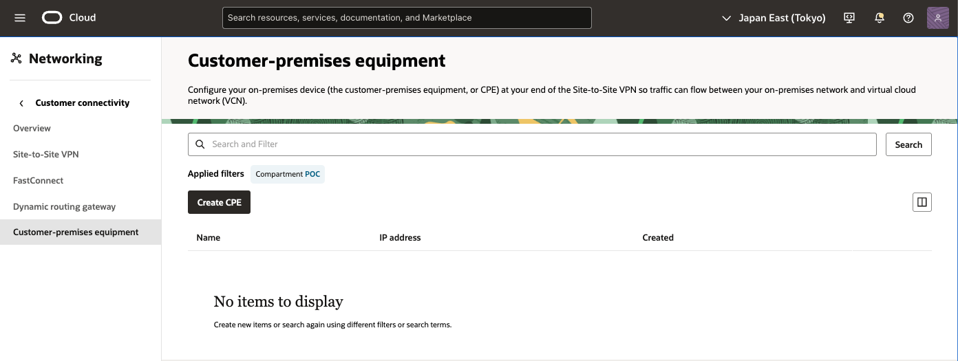
1) OCI コンソール
ナビゲーション・メニューを開き、[ネットワーキング]を選択し、[顧客接続]で、[顧客構内機器]を選択

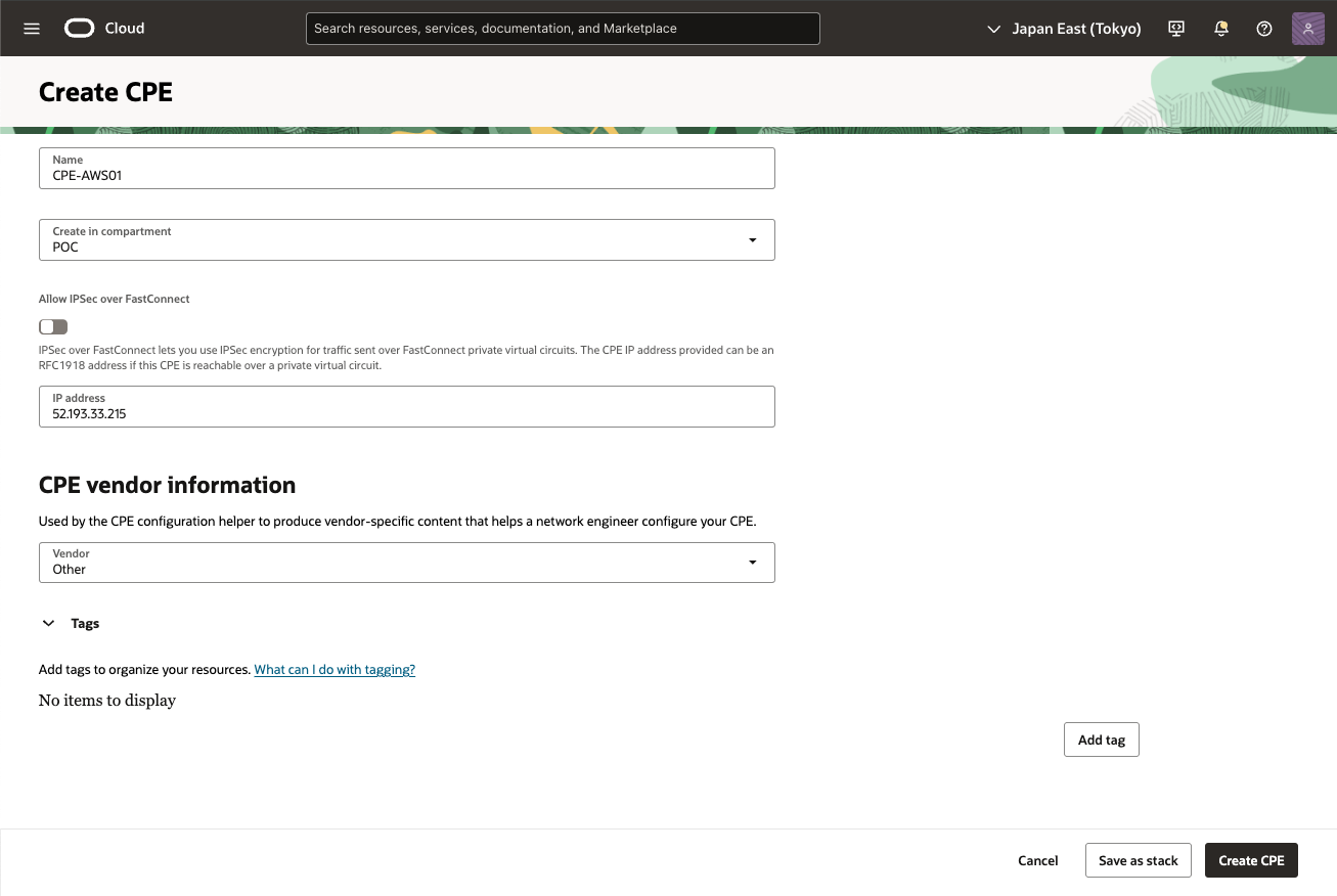
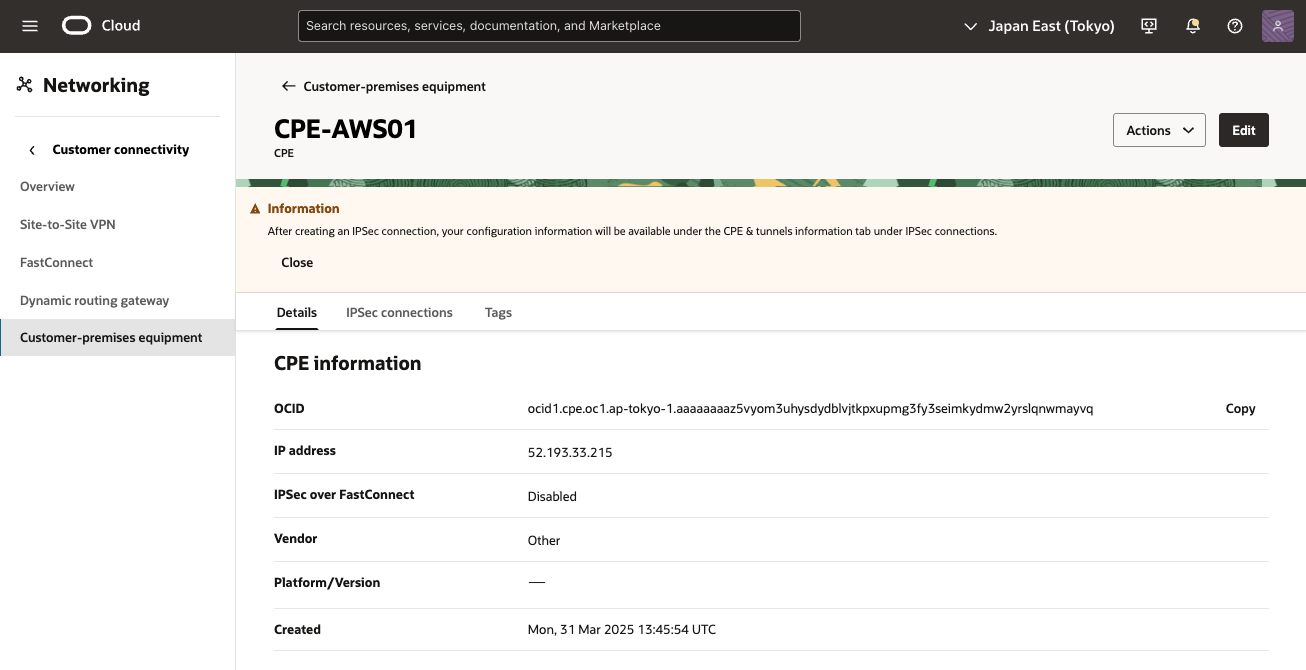
3) 顧客構内機作成 画面
次の値を入力し、[CPEの作成] をクリック
コンパートメントに作成:必要なVCNのコンパートメントを選択します。
・ 名前: CPEオブジェクトのわかりやすい名前を設定
・ IPアドレス: AWSからダウンロードした構成に示されている仮想プライベート・ゲートウェイの外部IPアドレス(ここでは、52.193.33.215)を入力。
・ CPEベンダー: [その他] を選択
● OCI - DRGの作成およびアタッチ
・ DRG 作成
Dynamic Routing Gateway (DRG)を作成します。
DRGは、オンプレミス・ネットワークと仮想クラウド・ネットワーク(VCNs)間のトラフィックのパスを提供する仮想ルーターとして機能し、VCNs間のトラフィックのルーティングにも使用できます。様々なタイプのアタッチメントを使用して、様々なリージョンおよびテナンシのコンポーネントを使用してカスタム・ネットワーク・トポロジを構築できます。各DRGアタッチメントには、DRGに入るパケットをネクスト・ホップにルーティングするために使用されるルート表が関連付けられています。静的ルートに加えて、アタッチされたネットワークからのルートは、オプションのインポート・ルート・ディストリビューションを使用してDRGルート表に動的にインポートされます。
1) OCI コンソール
ナビゲーション・メニューを開き、[ネットワーキング]を選択し、[顧客接続]で、[動的ルーティング・ゲートウェイ]を選択
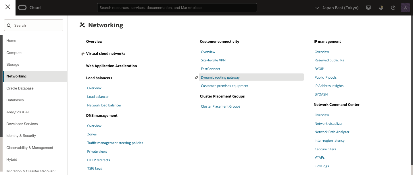
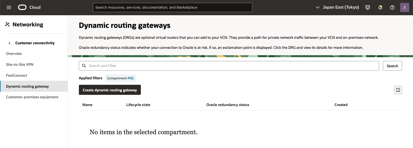
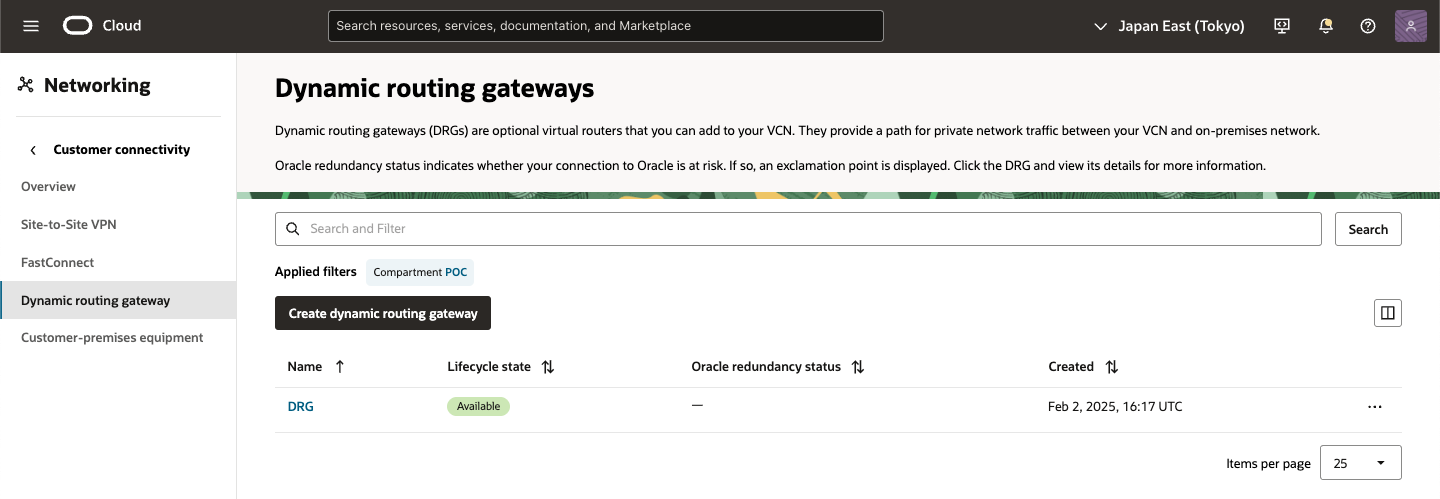
2) Dynamic routing gateways 画面
[リスト範囲]で、作業する権限があるコンパートメントを選択します。ページが更新されて、そのコンパートメントのリソースのみが表示されます。使用するコンパートメントが不明な場合は、管理者に問い合せてください。詳細は、アクセス制御を参照してください。
[動的ルーティング・ゲートウェイの作成]をクリック
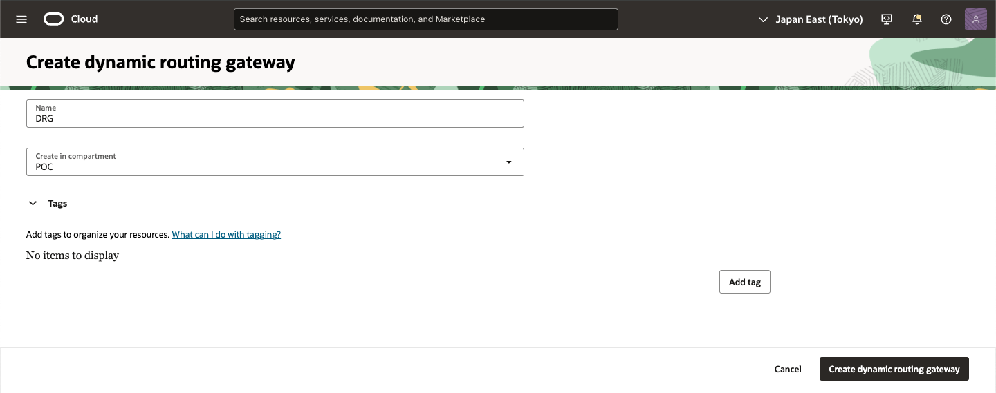
3) Create dynamic routing gateway 画面
次の値を入力し、[動的ルーティング・ゲートウェイの作成]をクリック
・ 名前: DRGのわかりやすい名前。一意にする必要はありません。後で変更できます。機密情報の入力は避けてください。
・ コンパートメントに作成: DRGを作成するコンパートメント。これは、現在作業しているコンパートメントとは異なる可能性があります。
・ (オプション)タグ: タグは後で適用できます。タグ付けの詳細は、リソース・タグを参照してください。
4) Create dynamic routing gateway 作成完了
新しいDRGが作成され、選択したコンパートメントの[動的ルーティング・ゲートウェイ]ページに表示されます。新しいDRGは、短い間[プロビジョニング中]状態になります。プロビジョニングの完了後にのみ、ネットワークの他の部分に接続できます。
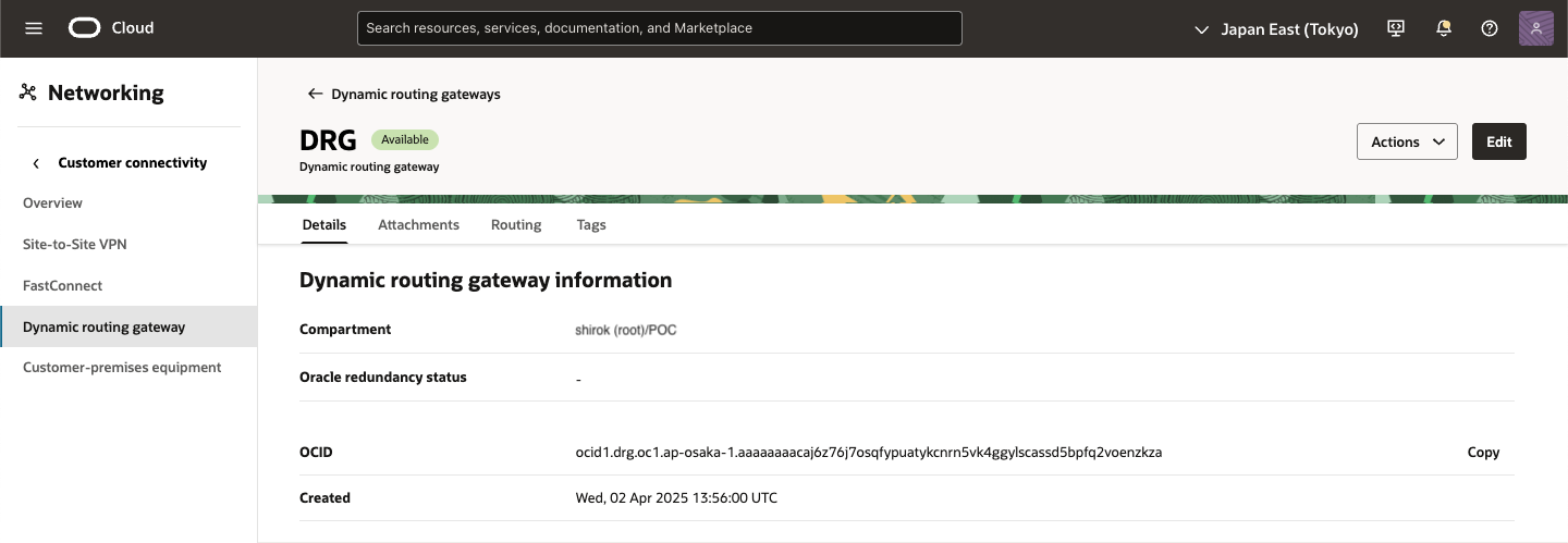
プロビジョニングには、2つのDRGルート表の作成が含まれます。1つは接続されたVCN用のルート表、もう1つは仮想回線やIPSecトンネルなどのその他のリソース用のルート表です。
DRGを作成すると、2つのデフォルト・ルート表が自動的に作成されます。1つはVCNアタッチメント用で、もう1つは他のすべてのアタッチメント用です。これは、2021年5月より前に作成されたレガシーDRGで使用されるデフォルトのルーティング動作と一致します。ルート表の詳細は、DRGルート表およびルート・ディストリビューションの作業を参照してください。
・ VCNへのDRGのアタッチ
VCNアタッチメントを作成します。
オンプレミス・ネットワークまたは別のリージョンのDRGからコンピュート・インスタンスにトラフィックをルーティングするには、DRGをVCNに明示的にアタッチする必要があります。VCNは同時に1つのDRGにのみアタッチできますが、DRGは複数のVCNにアタッチできます。アタッチメントはVCNを保持するコンパートメントに自動的に作成されます。アタッチされたVCNは、DRGと同じコンパートメントに存在する必要はありません。
1) 作成した DRG 画面
[VCNアタッチメント]タブをクリック
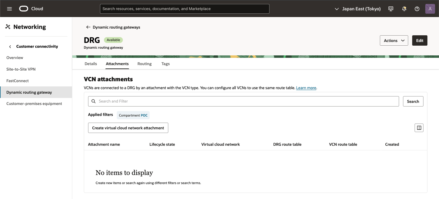
2) VCN attachments 画面
[仮想クラウド・ネットワーク・アタッチメントの作成] をクリック
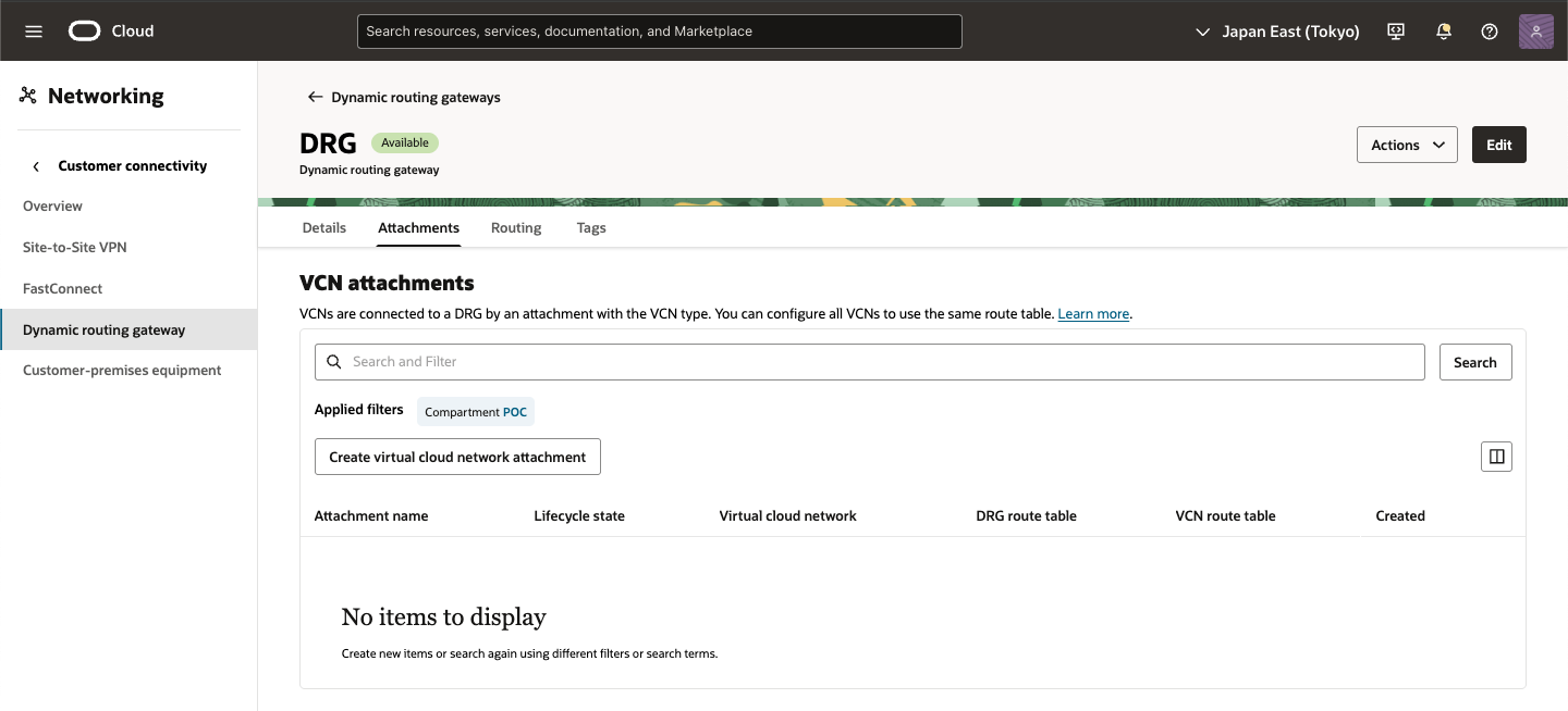
3) Create VCN attachment
次の情報を入力し、[VCNアタッチメントの作成]をクリック
・ アタッチメント名: わかりやすい説明の名前を入力。名前を入力しない場合、自動的に作成されます。
・ 仮想クラウド・ネットワーク: リストからVCNを選択します。コンパートメントの変更をクリックして、DRGにアタッチするVCNを含む別のコンパートメントを選択し、リストからVCNを選択することもできます。
・ (オプション) VCN route table: 「転送ルーティング用の高度なシナリオ」を設定している場合は、VCNルート表をDRGアタッチメントに関連付けられます(または、これは後から実行できます)
・ VCN route type: 伝播する BGPルートを [Subnet CIDR blocks], [VCN CIDR blocks]選択
・ (オプション)タグ: タグは後で適用できます。タグ付けの詳細は、リソース・タグを参照してください。
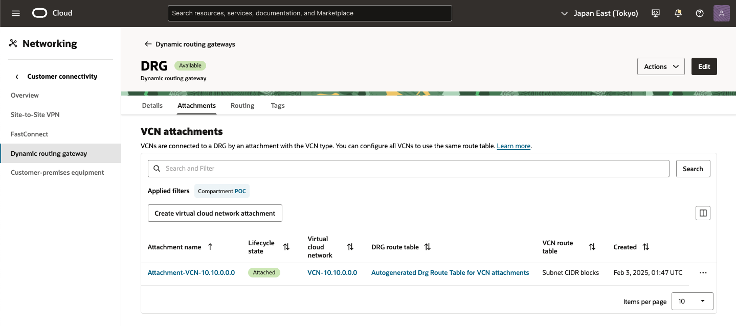
4) Create VCN attachment完了
短い間、アタッチメントは[アタッチ中]状態になります。アタッチメントの準備ができたら、サブネットのルート表にルート・ルールを作成し、サブネット・トラフィックをDRGに転送します。サブネットのトラフィックをDRGにルーティングするにはを参照してください。
● OCI - IPSec接続の作成
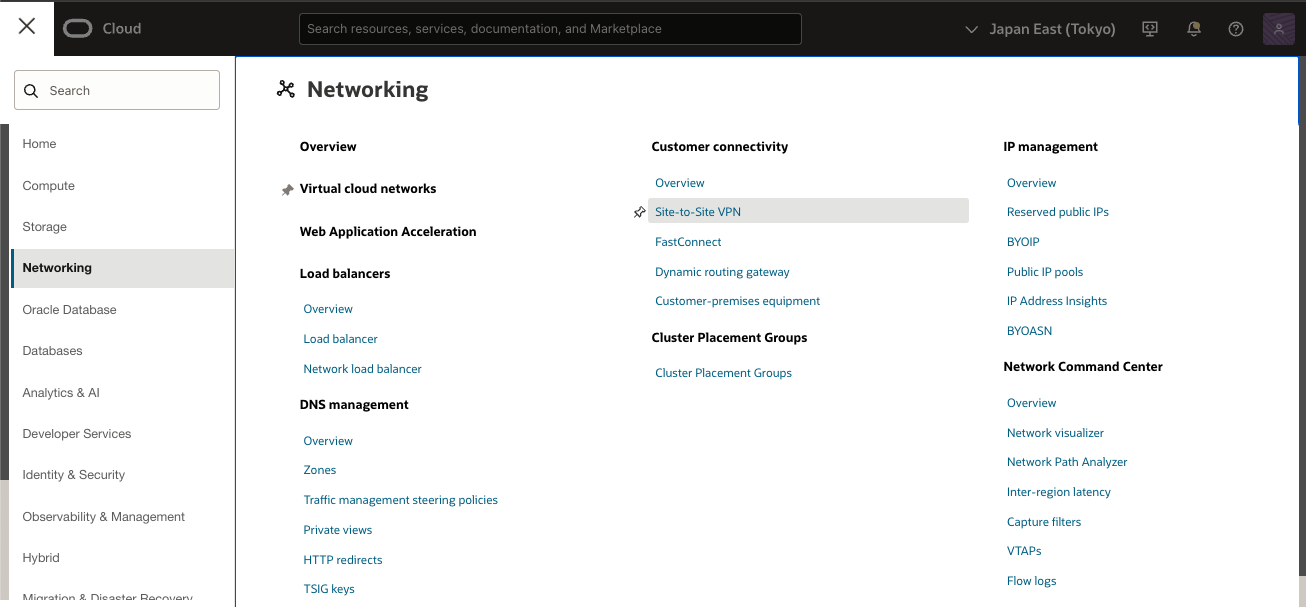
1) OCI コンソール
ナビゲーション・メニューを開き、[ネットワーキング]を選択し、[顧客接続]で、[サイト間VPN]を選択
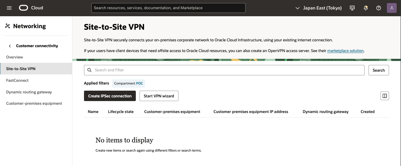
2) IPSec接続 画面
[IPSec接続の作成] をクリックします。
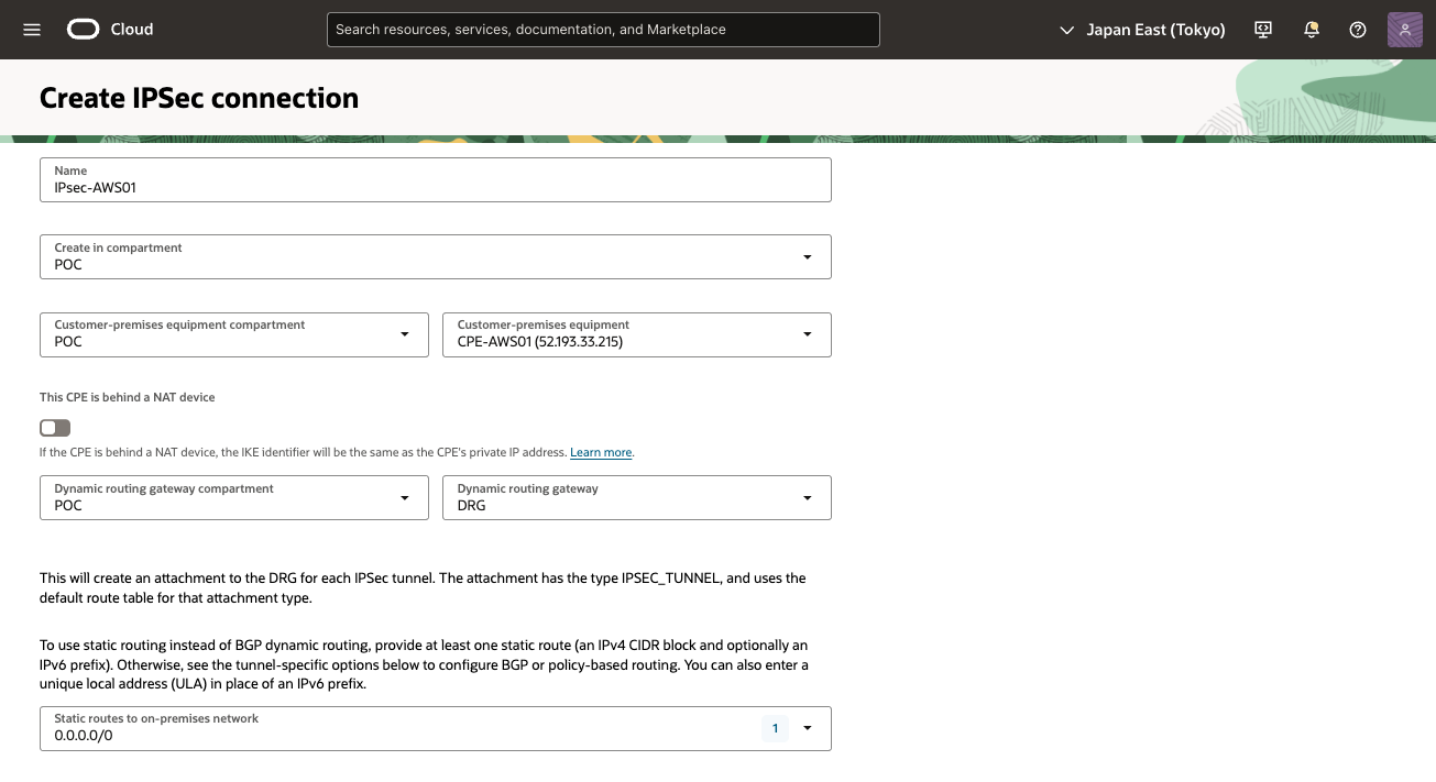
3) IPSec接続の作成 画面
次の値を入力し、[IPSec接続の作成]をクリックし、[IPSec接続の作成]をクリックします。
・ 名前: IPSec接続の記述名を入力
・ コンパートメントに作成: そのままにします(VCNのコンパートメント)
・ 顧客構内機器・コンパートメント: そのままにします(VCNのコンパートメント)。
・ 顧客構内機器: 事前に作成したCPEオブジェクトを選択
・ 動的ルーティング・ゲートウェイ・コンパートメント: そのままにします(VCNのコンパートメント)。
・ 動的ルーティング・ゲートウェイ: 事前に作成したDRGを選択
・ 静的ルートCIDR:デフォルト・ルート0.0.0.0/0を入力します。アクティブ・トンネルはBGPを使用するため、OCIはこのルートを無視します。
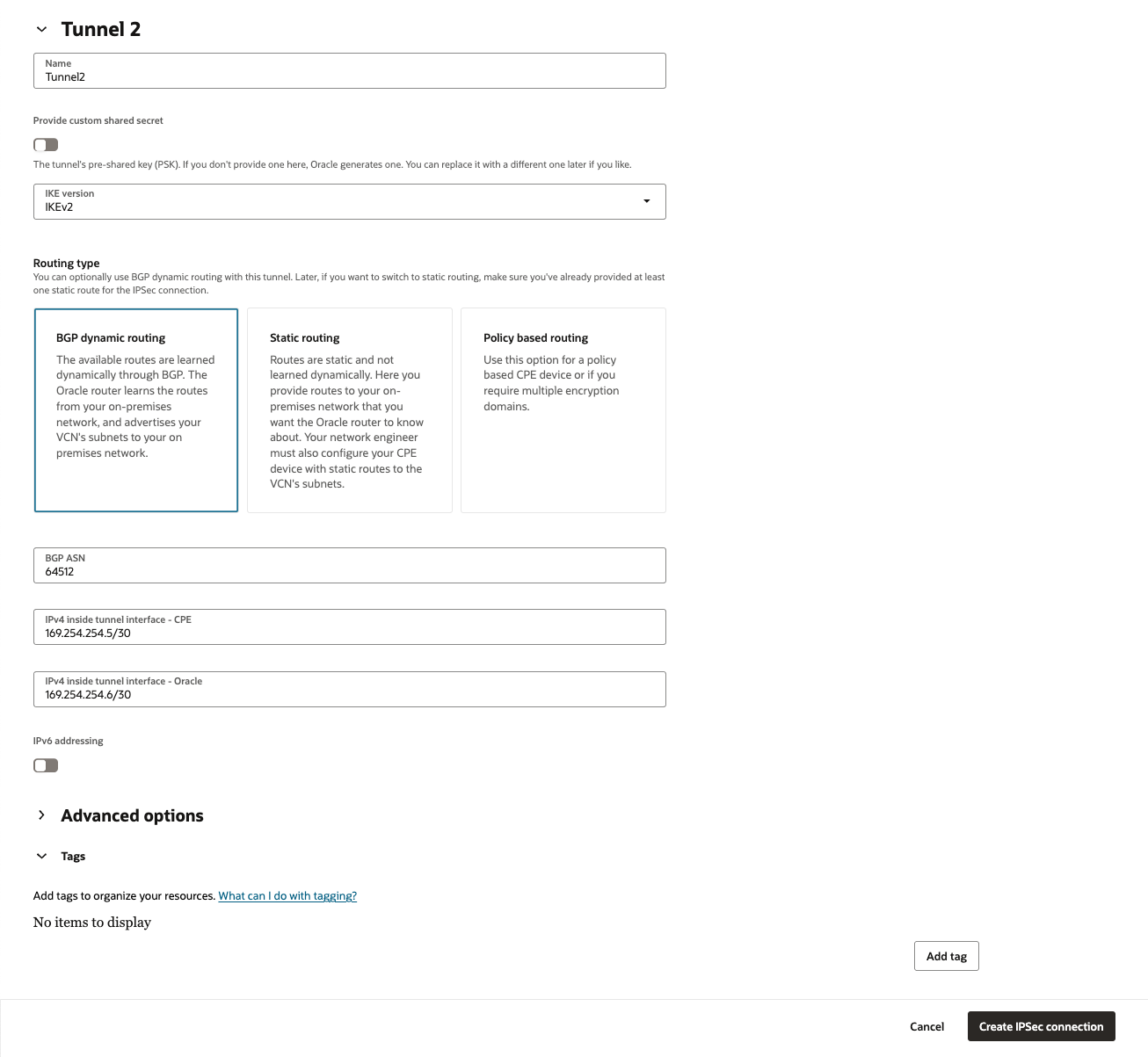
  IPSec接続の2番目のトンネルにはエントリが必要です。デフォルトでは静的ルーティングが使用されますが、アドレスはこのシナリオでは使用されていません。
  この接続に静的ルーティングを使用する場合は、AWS仮想ネットワークを表す静的ルートを入力します。IPSec接続ごとに最大10個の静的ルートを構成できます。

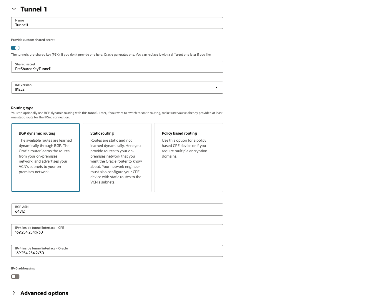
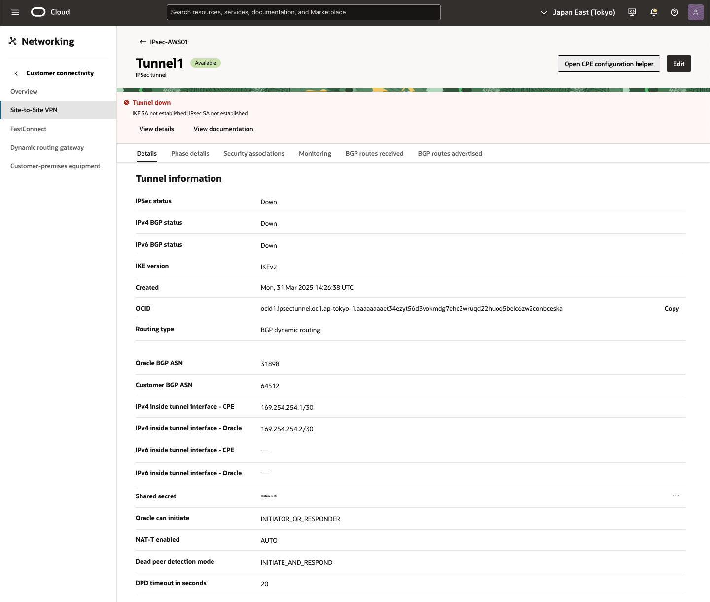
[トンネル1]タブで次の詳細を入力します(必須):

    ・ 名前:トンネルを示す名前を入力
    ・ カスタム共有シークレットの指定: このチェック・ボックスを選択し、事前に作成したAWS VPN構成ファイルを参照して事前共有キーを入力
    ・ IKEバージョン: IKEv2を選択します。
    ・ ルーティング・タイプ: [BGP動的ルーティング] を選択
    ・ BGP ASN: AWS VPN構成ファイルにある AWSで使用されるBGP ASNを入力
    ・ IPv4トンネル内インタフェース- CPE: AWS VPN構成ファイルを参照して、仮想プライベート・ゲートウェイの内部IP(ここでは、169.254.254.1/30) のCIDRを入力
    ・ IPv4トンネル内インタフェース- Oracle: OCIで使用される内部IPアドレスを入力します。AWS VPN構成ファイルを参照して、カスタマ・ゲートウェイの内部IPアドレス(ここでは、169.254.254.2/30) のCIDRを入力を入力
4) IPSec接続作成中
IPSec接続が作成され、ページに表示されます。この接続は、短い間[プロビジョニング中]状態になります。

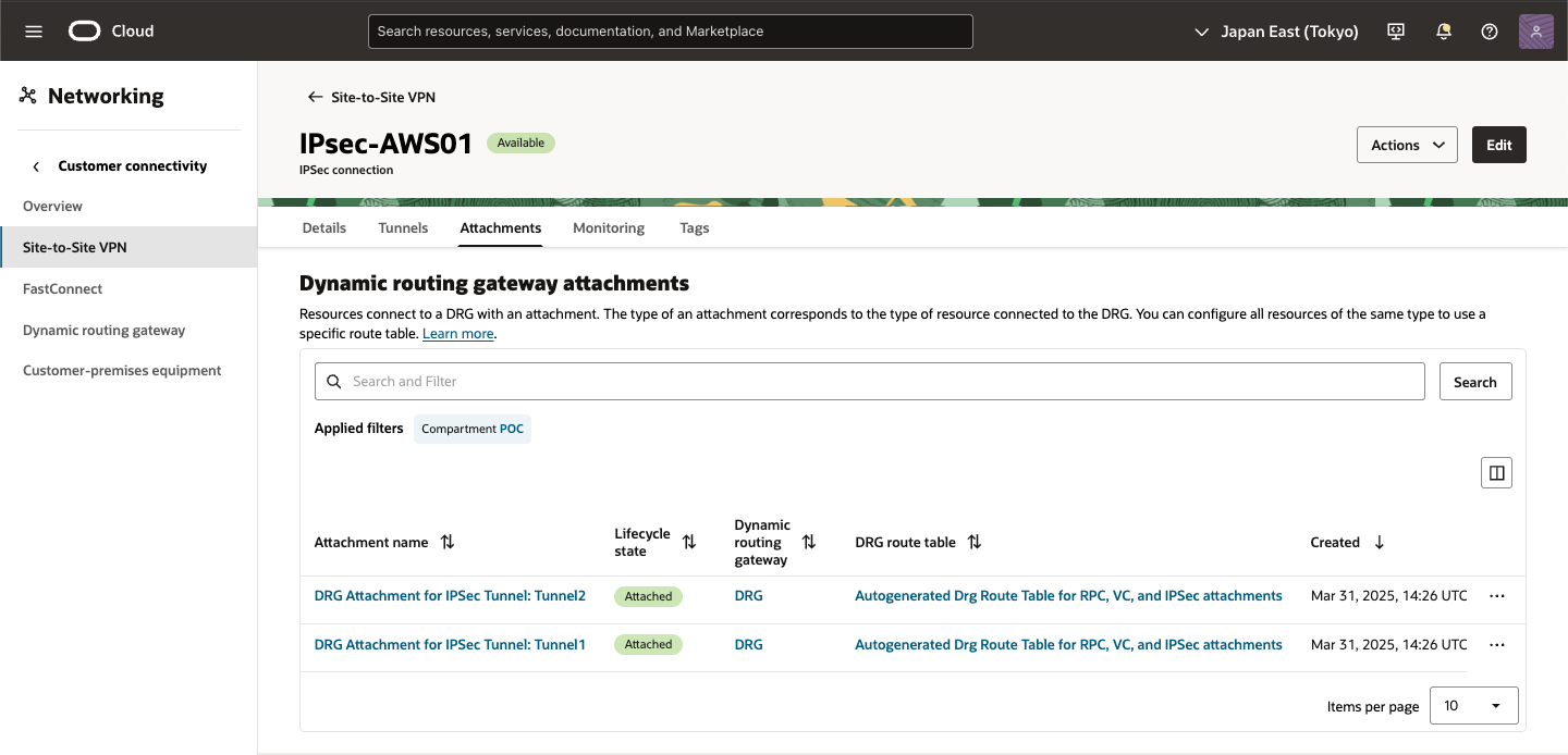
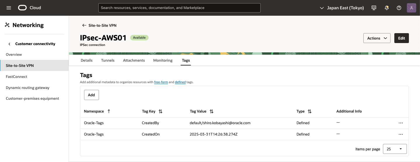
5) IPSec接続作成完了
IPSec接続をプロビジョニングしたら、トンネルの Oracle VPN IPアドレスを書き留めます。このアドレスは、AWSポータルで新しいカスタマ・ゲートウェイを作成するために使用されます。
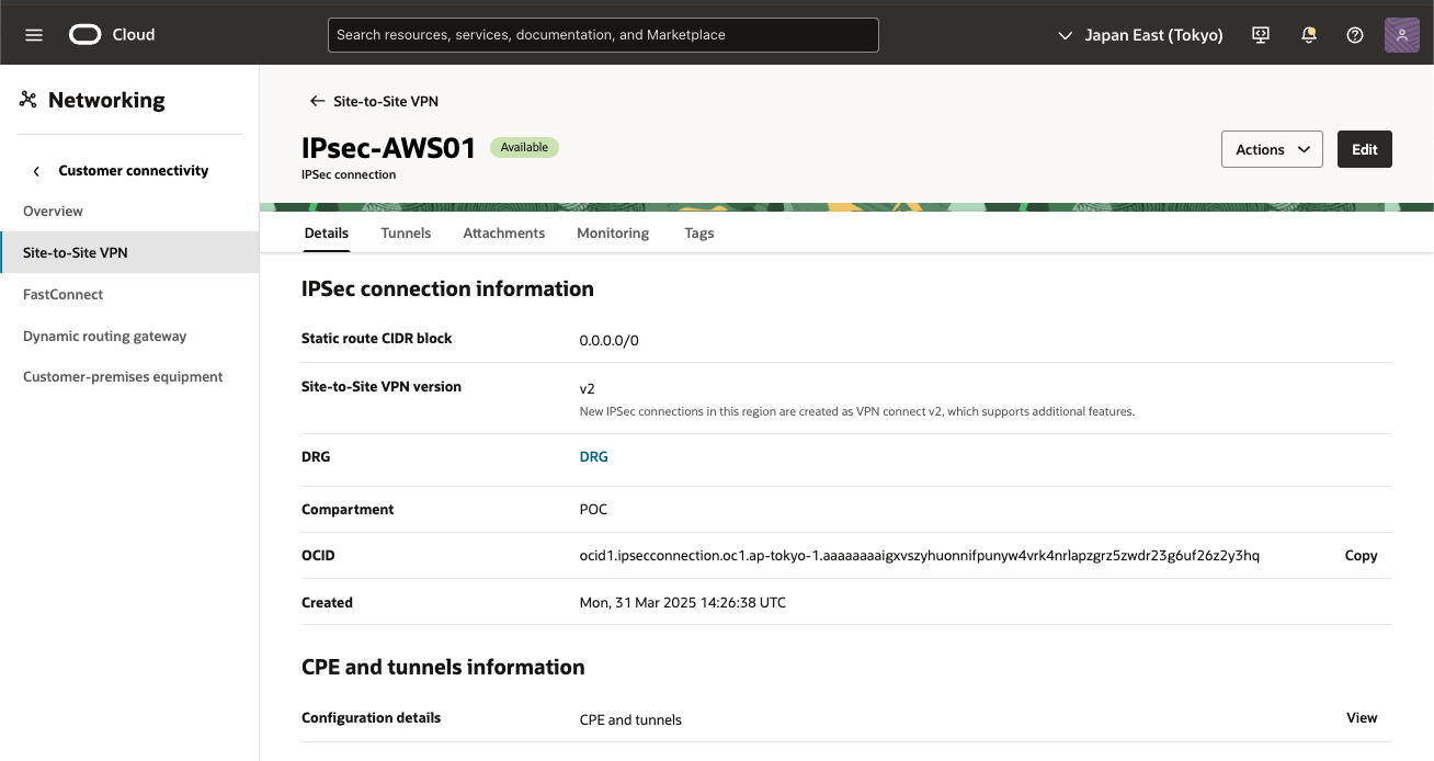
6) IPSec接続確認
[Tunnels] タブをクリックし、[Tunndel1] のOracle VPN IPアドレスを確認しメモします。
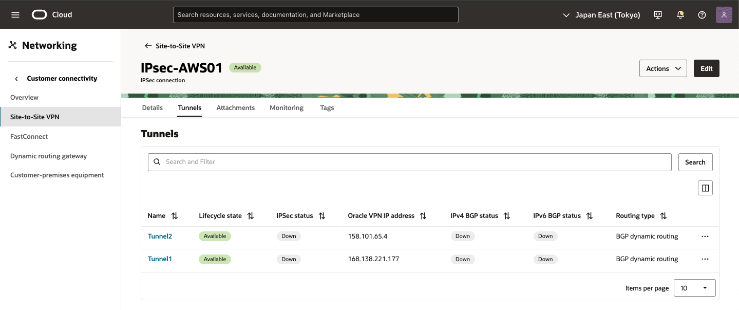

・ Tunnel01確認
作成した Tunnel をクリックすると詳細内容を確認できます。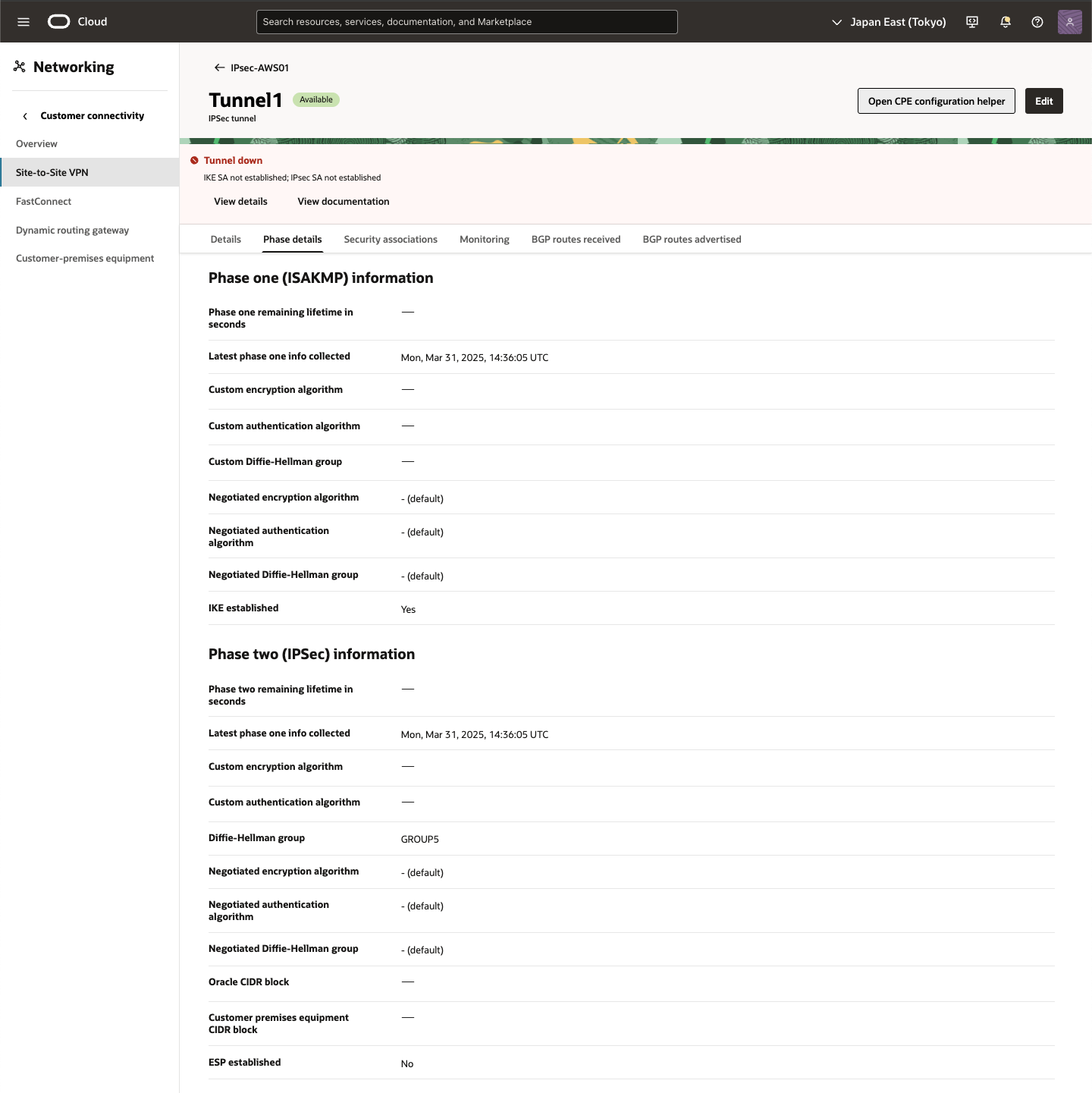
● AWS - 新規カスタマ・ゲートウェイの作成
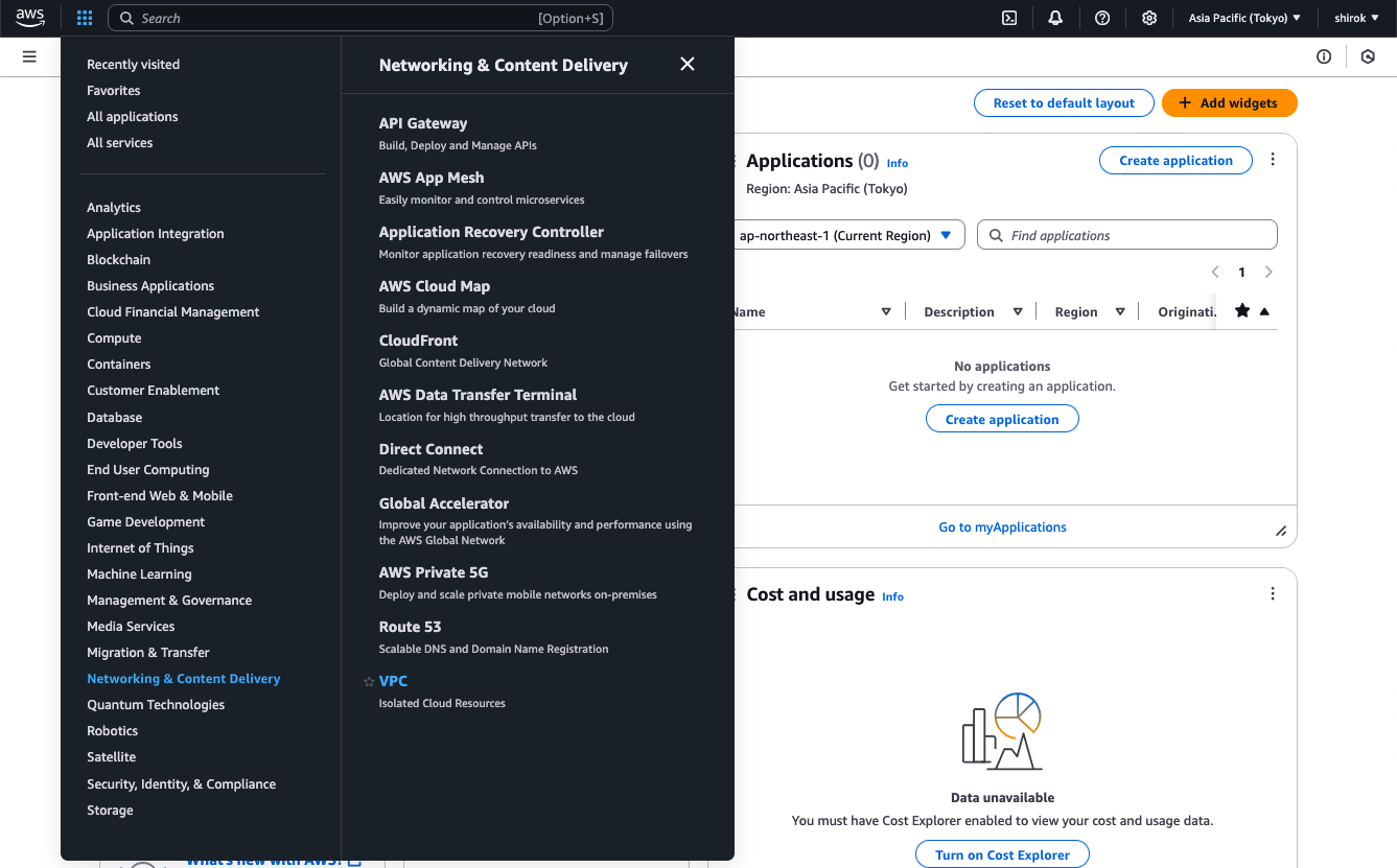
1) Amazon コンソール画面
メインの AWSポータルで、画面の左上にある[Services]メニューを展開し、[ネットワークおよびコンテンツ配信]の下の[VPC]をクリック
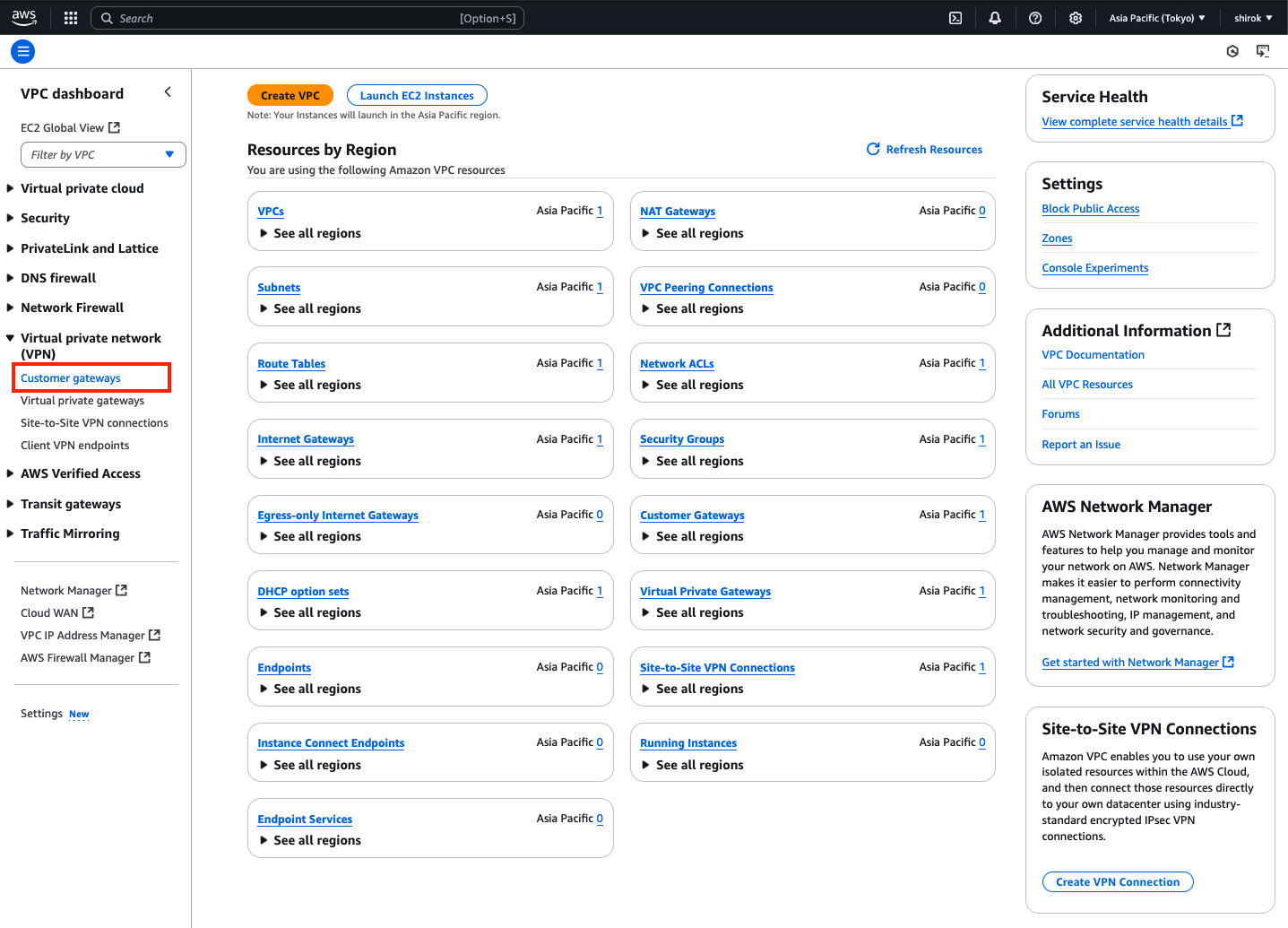
2) VPC 画面
左側のメニューで、下にスクロールして[Virtual Private Network (VPN)]の下の[Customer Gateway]をクリック
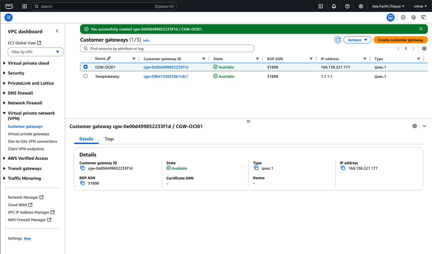
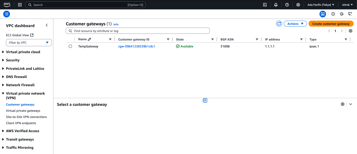
3) Customer gateway 画面
[ゲートウェイの作成]をクリックして、ゲートウェイを作成
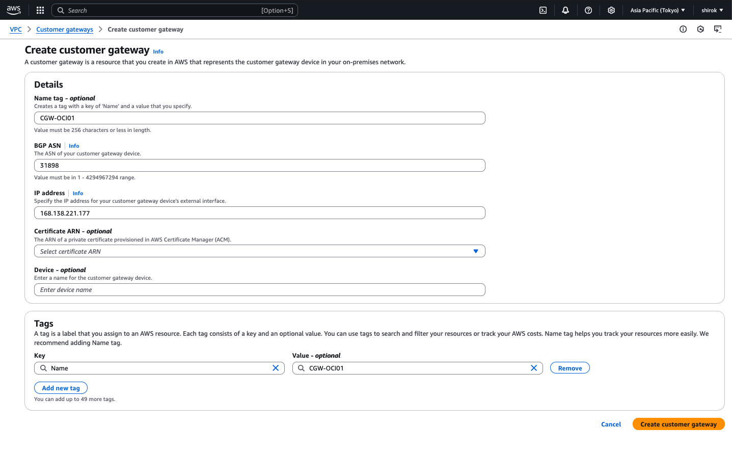
4) Create customer gateway 画面
次の詳細を入力し、[Create Customer Gateway] をクリックしてプロビジョニング
・ Name: この顧客ゲートウェイに名前を付けます。
・ Routing: [Dynamic] を選択
・ BGP ASN: Oracle の商用クラウド用 BGP ASN 31898 を入力
・ IP Address:前のタスクでメモしたトンネル1 の Oracle VPN IPアドレスを入力
● AWS - 新規カスタマ・ゲートウェイのVPN接続の変更
このタスクでは、一時カスタマ・ゲートウェイを、OCI VPN IPアドレスを使用するものに置き換えます。
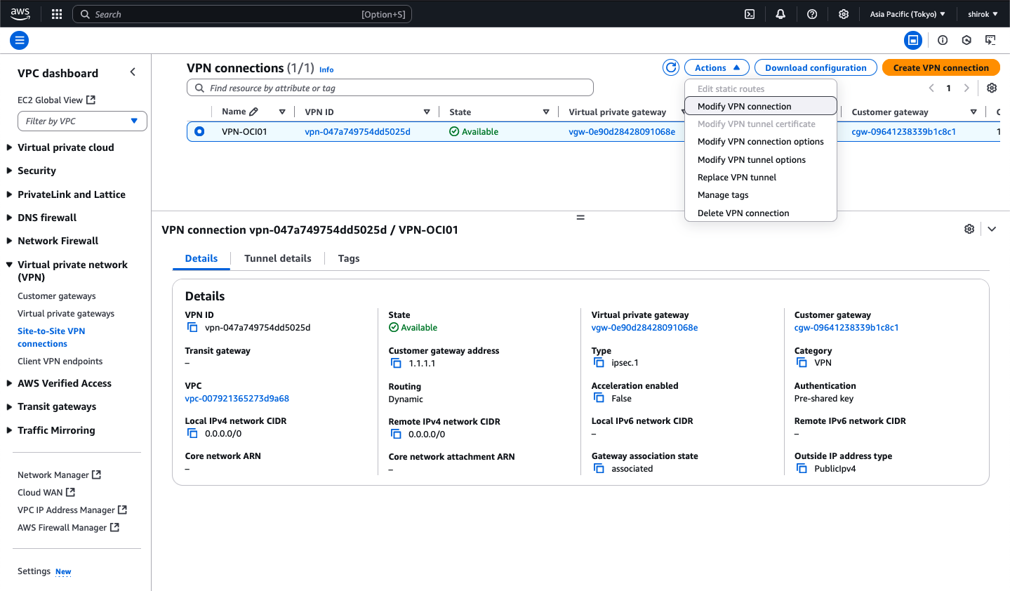
1) Site-to-Site VPN Connections 画面
AWSコンソールで、[Site-to-Site VPN Connections]をクリックし、策定した VPN接続を選択し、
[アクション]メニュー から、[VPN接続の変更]をクリック
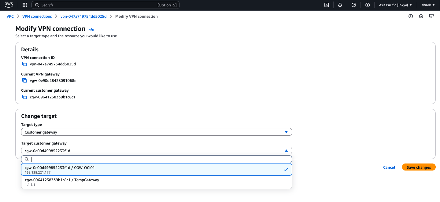
2) Modify VPN connection
次の詳細を入力し、[Save Changes]ボタンをクリックして構成を保存
・ ターゲット・タイプ: [顧客ゲートウェイ] を選択
・ Target Customer Gateway ID: リストから、OCI VPN IPアドレスを持つ新しいカスタマ・ゲートウェイを選択
3) Modify VPN connection 中〜
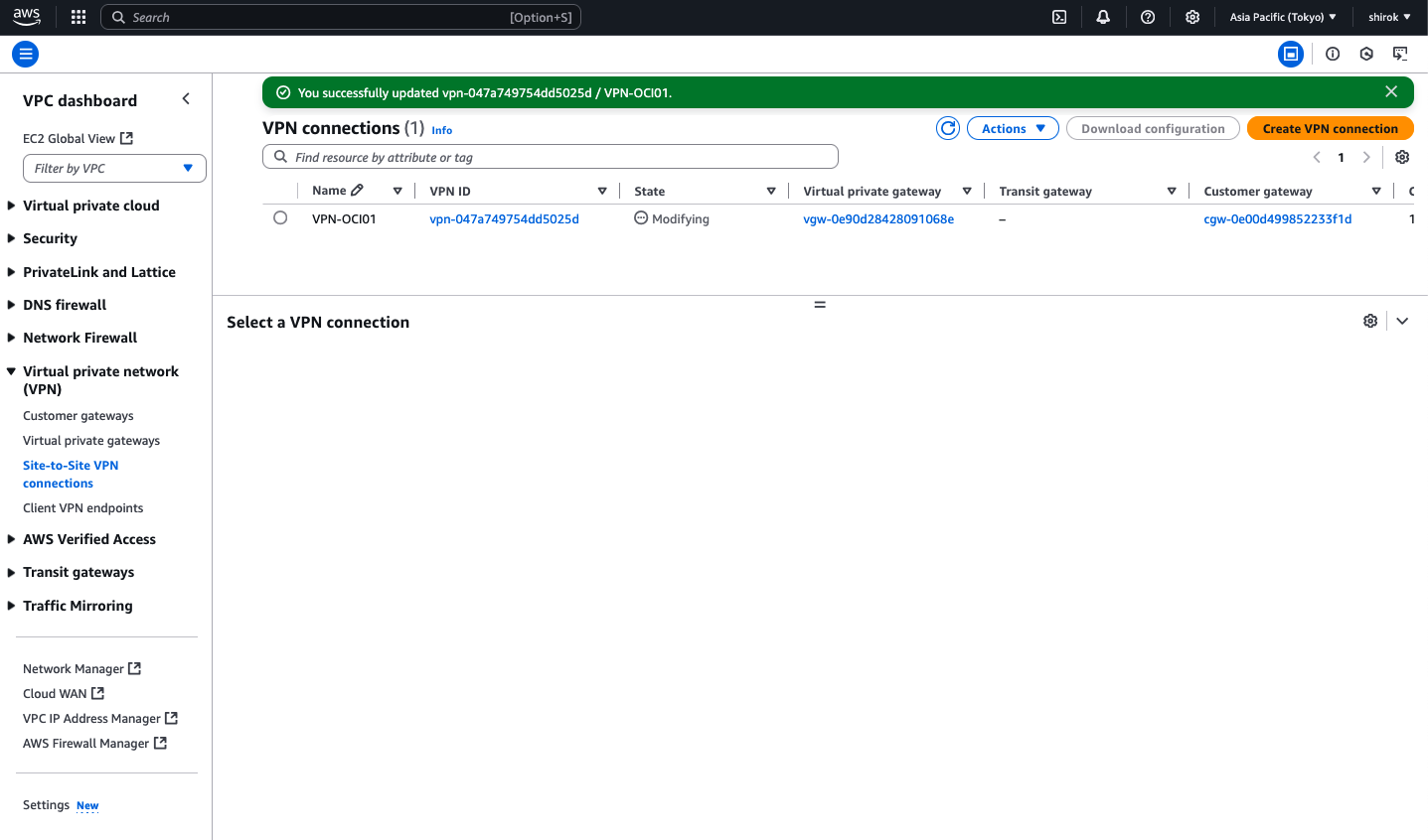
数分後、AWSはVPN接続のプロビジョニングを完了し、AWSとOCI間のIPSec VPNが起動します。
この時点で、一時カスタマ・ゲートウェイを削除できます。
● Site-to-Site VPN稼働確認
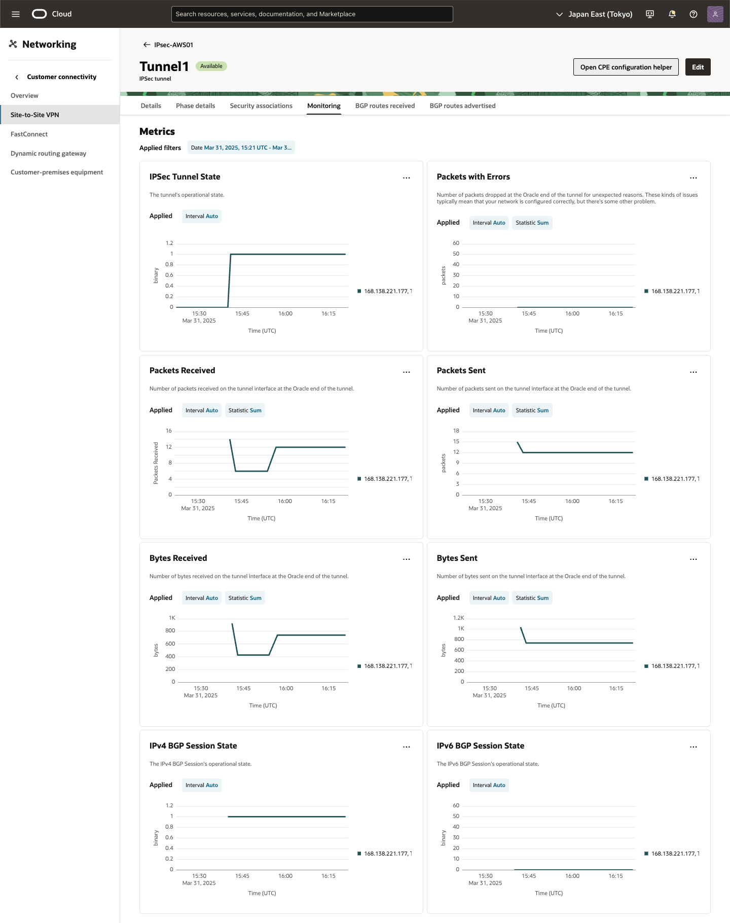
OCIのIPSec接続と、AWSのサイトツーサイトVPN接続を参照して、トンネルのステータスを確認します。
・ OCI 確認
IPSec接続の下のOCIトンネルに、IPSecステータスとして[稼働中]が表示され、稼働中のトンネルを確認できます。
また、IPv4 BGPステータスには、確立されたBGPセッションを示す[稼働中]が表示されます。

Tunnel1 をクリックし、[Monitoring]タブを選択すると稼働状態、パフォーマンスをモニターできます。詳細は、モニタリングおよび通知を参照してください。
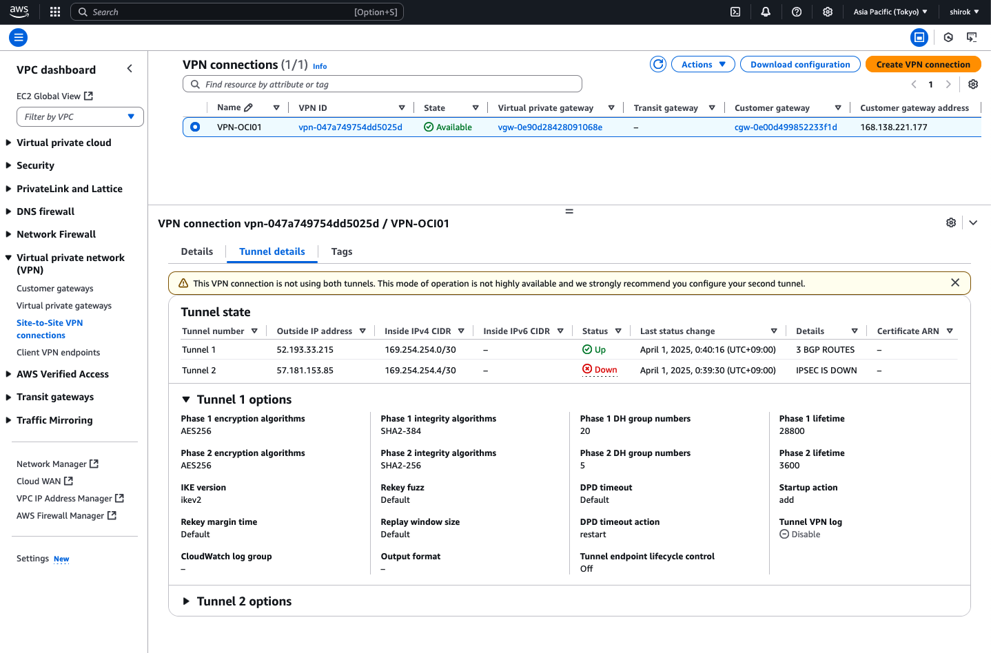
・ AWS 確認
AWSのサイト間VPN接続の[トンネル詳細]タブにあるトンネル・ステータスに、[稼働中]が表示されます。
稼働状態、パフォーマンスのモニターは、AWS Site-to-Site VPN 接続のモニタリングを参考にモニタリング設定をします。
■ OCI-AWSインスタンス間接続確認
OCI と AWS の インスタンス間接続に必要なルート・テーブルの設定確認と疎通確認します。
● AWS ルート・テーブル設定と確認
ルート伝達を有効化します
ルートテーブルは、VPC からのネットワークトラフィックの転送先を指定します。VPC ルートテーブルで、リモートネットワークのルートを追加し、仮想プライベートゲートウェイをターゲットとして指定する必要があります。これにより、リモートネットワーク向けの VPC からのトラフィックが、仮想プライベートゲートウェイおよび、いずれかの VPN トンネルを経由してルーティングされます。ルートテーブルのルート伝播を有効にすると、ネットワークルートは自動的にテーブルに伝播されます。
ルート伝達は、仮想プライベートゲートウェイがルートテーブルにルートを自動的に伝達できるようにします。これは、VPN ルートを手動で追加または削除する必要がないことを意味します。
・ OCI VCN Subnet ルート情報受信設定と受信確認
1) AWS コンソール
Amazon VPC コンソール (https://console.aws.amazon.com/vpc/) を開き、
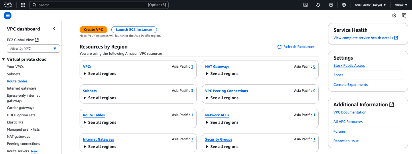
ナビゲーションペインで [ルートテーブル] (Route tables) を選択して、ルートテーブルを選択
2) Route tables 画面
対象の Route table IDを選択し、[Edit route propagation (ルート伝達を編集)] の順に選択
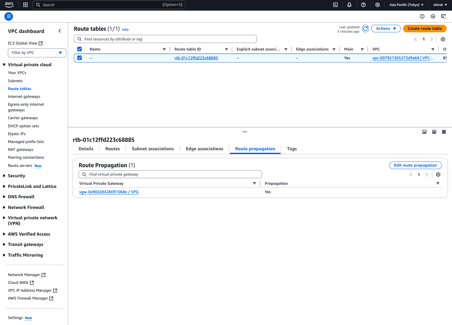
3) Edit route propagation 画面
仮想プライベートゲートウェイの横にある [Enable] (有効化) チェックボックスをオンにし、[Save] (保存) をクリック

4) Routes画面
OCI から送信されている OCI VCN Subnet のルート伝達を確認

● OCI ルート・テーブル設定と確認
・ AWS VPCルート情報受信確認
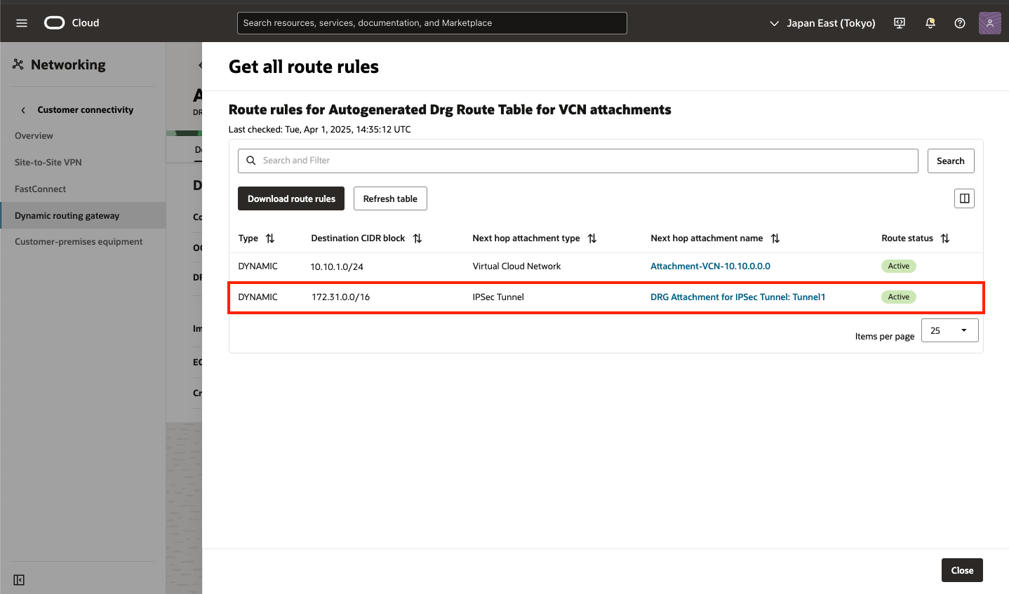
AWS VPCルート情報は BGP通じて DRGのルート・テーブルに伝播されます。
DRGのルート・テーブルを確認することでAWSのルート情報を確認できます。
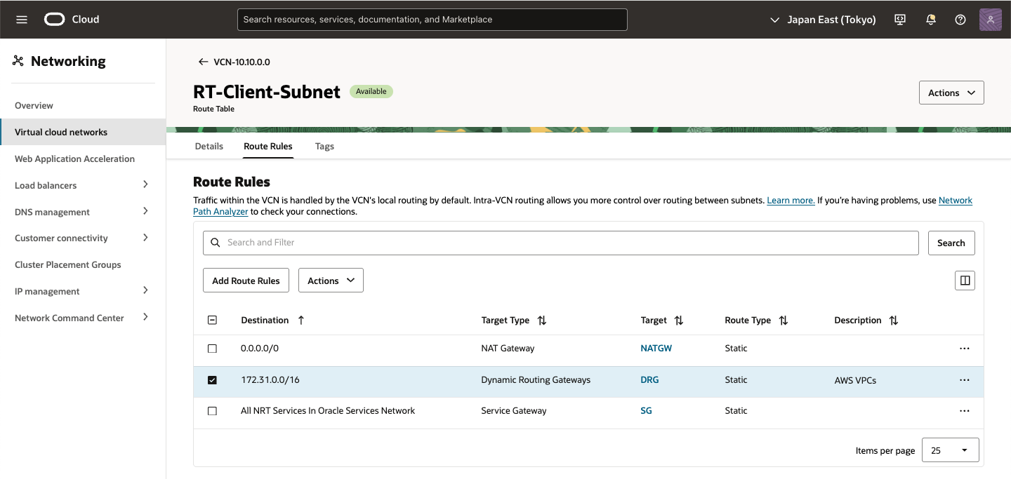
また、OCI VCN Subnetに付属のルートテーブルへは自動伝搬されないため手動でAWSへ通じるようルート・ルールを追加します。
1) DRG 画面
対象のDRG画面を表示し、[Routing]タブをクリック
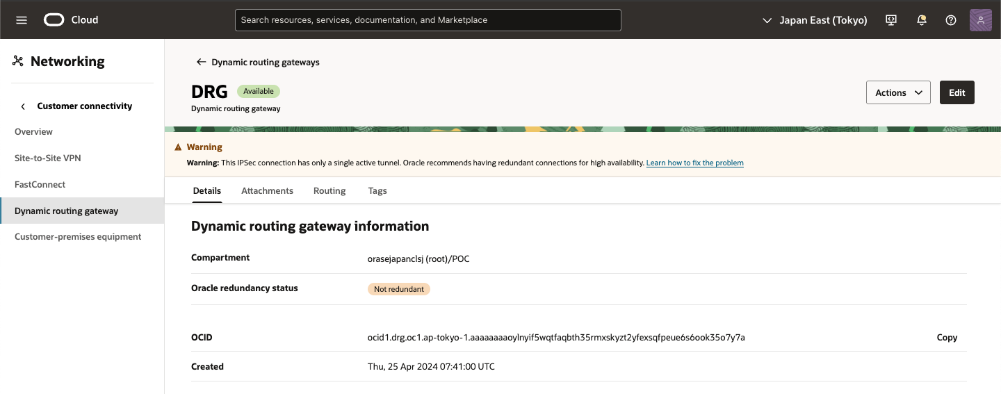
2) DRG Routing 画面
DRG route tables 項目にある VCNに通じる DRG route table (Autogenerated Drg Route Table for VCN attachments) をクリック
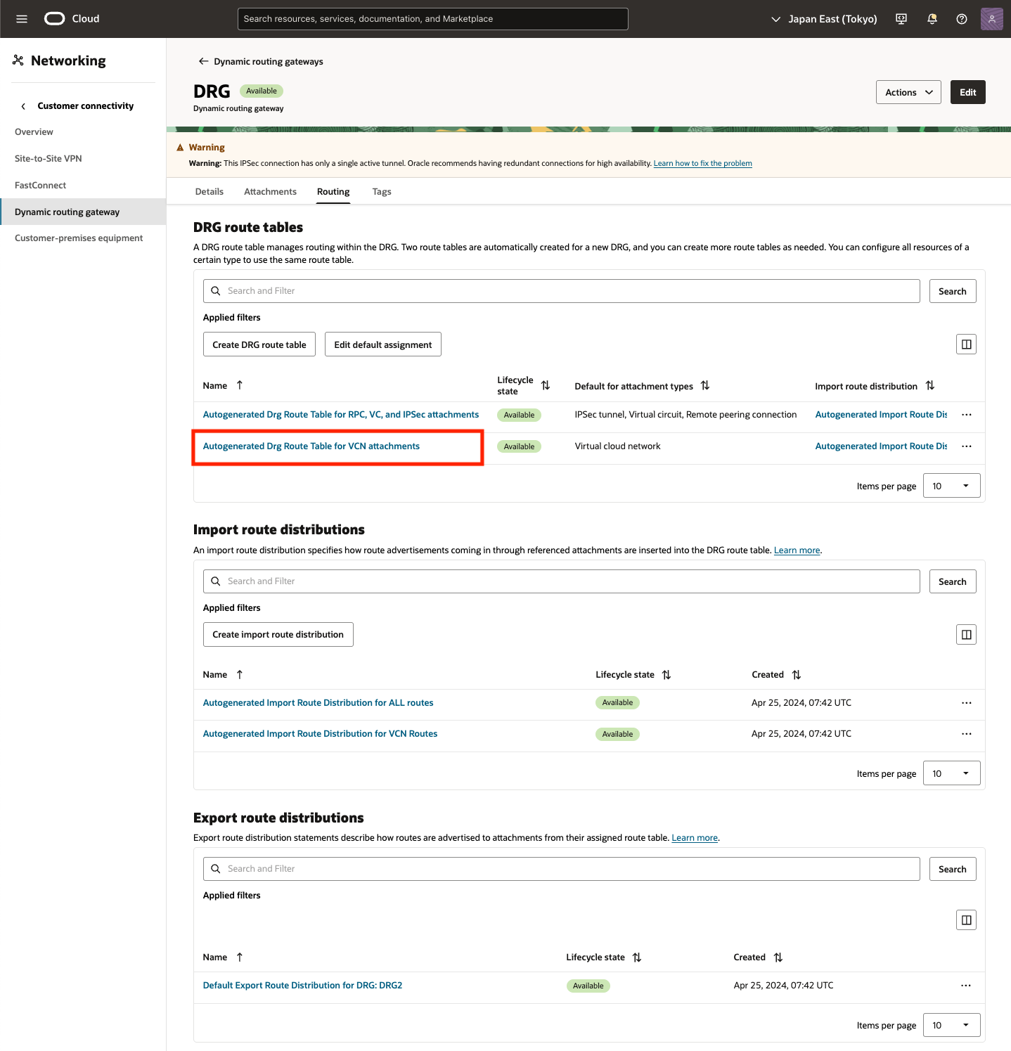
3) DRG Routing DRG route table 画面
[Get all route rules] をクリック
4) Get all route rules 画面
Site to Site VPN接続が確立されていると、対向から BGP送信されるルート情報が表示されます。
・ OCI ルート・テーブル設定
外部からBGPルートを受信した DRGのルートをVCN Subnet のルート・テーブルへ登録します。
1) VCN の Route Roules画面
AWS VPC の CIDRを DRG経由するルート・ルールを追加
● AWS AZ-1a -> OCI 接続確認
・ ssh 接続
[ec2-user@ip-172-31-1-11 ~]$ ssh -i id_rsa opc@10.10.1.2
The authenticity of host '10.10.1.2 (10.10.1.2)' can't be established.
ED25519 key fingerprint is SHA256:r9TbpSAHr+U82OV1KtRjlkIDXn8IEF8+rwiFJ4psSmY.
This key is not known by any other names
Are you sure you want to continue connecting (yes/no/[fingerprint])? yes
Warning: Permanently added '10.10.1.2' (ED25519) to the list of known hosts.
Activate the web console with: systemctl enable --now cockpit.socket

Last login: Wed Apr  2 07:40:09 2025 from 172.31.1.11

[opc@oci-inst ~]$ hostname
oci-inst
・ traceroute
[ec2-user@ip-172-31-1-11 ~]$ traceroute 10.10.1.2
traceroute to 10.10.1.2 (10.10.1.2), 30 hops max, 60 byte packets
 1  * * *
 2  * * *
 3  ip-10-10-1-2.ap-northeast-1.compute.internal (10.10.1.2)  4.095 ms !X  4.074 ms !X  4.053 ms !X
・ Ping
[ec2-user@ip-172-31-1-11 ~]$ sudo ping 10.10.1.2 -i 0.001 -c 10
PING 10.10.1.2 (10.10.1.2) 56(84) bytes of data.
64 bytes from 10.10.1.2: icmp_seq=1 ttl=61 time=3.99 ms
64 bytes from 10.10.1.2: icmp_seq=2 ttl=61 time=3.76 ms
64 bytes from 10.10.1.2: icmp_seq=3 ttl=61 time=3.71 ms
64 bytes from 10.10.1.2: icmp_seq=4 ttl=61 time=3.72 ms
64 bytes from 10.10.1.2: icmp_seq=5 ttl=61 time=3.74 ms
64 bytes from 10.10.1.2: icmp_seq=6 ttl=61 time=3.73 ms
64 bytes from 10.10.1.2: icmp_seq=7 ttl=61 time=3.69 ms
64 bytes from 10.10.1.2: icmp_seq=8 ttl=61 time=3.74 ms
64 bytes from 10.10.1.2: icmp_seq=9 ttl=61 time=3.73 ms
64 bytes from 10.10.1.2: icmp_seq=10 ttl=61 time=3.78 ms

--- 10.10.1.2 ping statistics ---
10 packets transmitted, 10 received, 0% packet loss, time 34ms
rtt min/avg/max/mdev = 3.692/3.756/3.988/0.080 ms
● OCI -> AWS AZ-1a 接続確認
・ ssh 接続
[opc@oci-inst ~]$ ssh -i EC2-Compute.pem ec2-user@172.31.1.11
The authenticity of host '172.31.1.11 (172.31.1.11)' can't be established.
ECDSA key fingerprint is SHA256:J8ECfsu+6tmF7JVzkLhja68NLwfmXRFkjI9p3EaKR8M.
Are you sure you want to continue connecting (yes/no/[fingerprint])? yes
Warning: Permanently added '172.31.1.11' (ECDSA) to the list of known hosts.
   ,     #_
   ~\_  ####_        Amazon Linux 2023
  ~~  \_#####\
  ~~     \###|
  ~~       \#/ ___   https://aws.amazon.com/linux/amazon-linux-2023
   ~~       V~' '->
    ~~~         /
      ~~._.   _/
         _/ _/
       _/m/'
Last login: Wed Apr  2 06:11:06 2025 from 133.32.216.136

[ec2-user@ip-172-31-1-11 ~]$ hostname
ip-172-31-1-11.ap-northeast-1.compute.internal
・ traceroute
[root@oci-inst ~]# traceroute 172.31.1.11
traceroute to 172.31.1.11 (172.31.1.11), 30 hops max, 60 byte packets
 1  140.91.206.168 (140.91.206.168)  0.190 ms 140.91.206.136 (140.91.206.136)  0.159 ms 140.91.206.108 (140.91.206.108)  0.165 ms
 2  * * *
 3  * * *
 4  172.31.1.11 (172.31.1.11)  4.093 ms  4.085 ms  4.056 ms
・ Ping
[opc@oci-inst ~]$ ping 172.31.1.11 -c 10
PING 172.31.1.11 (172.31.1.11) 56(84) bytes of data.
64 bytes from 172.31.1.11: icmp_seq=1 ttl=125 time=3.93 ms
64 bytes from 172.31.1.11: icmp_seq=2 ttl=125 time=3.92 ms
64 bytes from 172.31.1.11: icmp_seq=3 ttl=125 time=3.90 ms
64 bytes from 172.31.1.11: icmp_seq=4 ttl=125 time=3.89 ms
64 bytes from 172.31.1.11: icmp_seq=5 ttl=125 time=3.92 ms
64 bytes from 172.31.1.11: icmp_seq=6 ttl=125 time=3.86 ms
64 bytes from 172.31.1.11: icmp_seq=7 ttl=125 time=3.94 ms
64 bytes from 172.31.1.11: icmp_seq=8 ttl=125 time=3.99 ms
64 bytes from 172.31.1.11: icmp_seq=9 ttl=125 time=3.90 ms
64 bytes from 172.31.1.11: icmp_seq=10 ttl=125 time=3.94 ms

--- 172.31.1.11 ping statistics ---
10 packets transmitted, 10 received, 0% packet loss, time 9017ms
rtt min/avg/max/mdev = 3.862/3.919/3.990/0.090 ms

[opc@oci-inst ~]$ sudo ping 172.31.1.11 -c 10 -i 0.01
PING 172.31.1.11 (172.31.1.11) 56(84) bytes of data.
64 bytes from 172.31.1.11: icmp_seq=1 ttl=125 time=3.92 ms
64 bytes from 172.31.1.11: icmp_seq=2 ttl=125 time=3.71 ms
64 bytes from 172.31.1.11: icmp_seq=3 ttl=125 time=3.70 ms
64 bytes from 172.31.1.11: icmp_seq=4 ttl=125 time=3.68 ms
64 bytes from 172.31.1.11: icmp_seq=5 ttl=125 time=3.69 ms
64 bytes from 172.31.1.11: icmp_seq=6 ttl=125 time=3.69 ms
64 bytes from 172.31.1.11: icmp_seq=7 ttl=125 time=3.70 ms
64 bytes from 172.31.1.11: icmp_seq=8 ttl=125 time=3.73 ms
64 bytes from 172.31.1.11: icmp_seq=9 ttl=125 time=3.68 ms
64 bytes from 172.31.1.11: icmp_seq=10 ttl=125 time=3.68 ms

--- 172.31.1.11 ping statistics ---
10 packets transmitted, 10 received, 0% packet loss, time 90ms
rtt min/avg/max/mdev = 3.681/3.717/3.916/0.091 ms
・ Sockperf TCP
[root@ip-172-31-1-11 ~]# /opt/sockperf-3.8/sockperf sr --tcp -p 15000
sockperf: == version #3.8-no.git ==
sockperf: [SERVER] listen on:
[ 0] IP = ::              PORT = 15000 # TCP
sockperf: Warmup stage (sending a few dummy messages)...
sockperf: [tid 37743] using recvfrom() to block on socket(s)
[root@oci-inst sockperf-3.8]# ./sockperf ping-pong -i 172.31.1.11 --tcp -t 60 -p 15000 --full-rtt
sockperf: == version #3.8-no.git ==
sockperf[CLIENT] send on:sockperf: using recvfrom() to block on socket(s)

[ 0] IP = 172.31.1.11     PORT = 15000 # TCP
sockperf: Warmup stage (sending a few dummy messages)...
sockperf: Starting test...
sockperf: Test end (interrupted by timer)
sockperf: Test ended
sockperf: [Total Run] RunTime=60.000 sec; Warm up time=400 msec; SentMessages=15513; ReceivedMessages=15512
sockperf: ========= Printing statistics for Server No: 0
sockperf: [Valid Duration] RunTime=59.547 sec; SentMessages=15395; ReceivedMessages=15395
sockperf: ====> avg-rtt=3867.864 (std-dev=179.151, mean-ad=74.425, median-ad=40.981, siqr=31.322, cv=0.046, std-error=1.444, 99.0% ci=[3864.145, 3871.583])
sockperf: # dropped messages = 0; # duplicated messages = 0; # out-of-order messages = 0
sockperf: Summary: Round trip is 3867.864 usec
sockperf: Total 15395 observations; each percentile contains 153.95 observations
sockperf: ---> <MAX> observation = 10280.461
sockperf: ---> percentile 99.999 = 10280.461
sockperf: ---> percentile 99.990 = 7804.272
sockperf: ---> percentile 99.900 = 6163.578
sockperf: ---> percentile 99.000 = 4510.400
sockperf: ---> percentile 90.000 = 3948.239
sockperf: ---> percentile 75.000 = 3868.203
sockperf: ---> percentile 50.000 = 3828.825
sockperf: ---> percentile 25.000 = 3805.557
sockperf: ---> <MIN> observation = 3753.299
・ Sockperf UDP
[root@ip-172-31-1-11 ~]# sudo /opt/sockperf-3.8/sockperf sr -p 15000
sockperf: == version #3.8-no.git ==
sockperf: [SERVER] listen on:
[ 0] IP = ::              PORT = 15000 # UDP
sockperf: Warmup stage (sending a few dummy messages)...
sockperf: [tid 38612] using recvfrom() to block on socket(s)
[root@oci-inst sockperf-3.8]# ./sockperf ping-pong -i 172.31.1.11 -t 60 -p 15000 --full-rtt
sockperf: == version #3.8-no.git ==
sockperf[CLIENT] send on:sockperf: using recvfrom() to block on socket(s)

[ 0] IP = 172.31.1.11     PORT = 15000 # UDP
sockperf: Warmup stage (sending a few dummy messages)...
sockperf: Starting test...
sockperf: Test end (interrupted by timer)
sockperf: Test ended
sockperf: [Total Run] RunTime=60.000 sec; Warm up time=400 msec; SentMessages=15847; ReceivedMessages=15846
sockperf: ========= Printing statistics for Server No: 0
sockperf: [Valid Duration] RunTime=59.548 sec; SentMessages=15726; ReceivedMessages=15726
sockperf: ====> avg-rtt=3786.513 (std-dev=179.089, mean-ad=64.307, median-ad=36.782, siqr=28.519, cv=0.047, std-error=1.428, 99.0% ci=[3782.834, 3790.192])
sockperf: # dropped messages = 0; # duplicated messages = 0; # out-of-order messages = 0
sockperf: Summary: Round trip is 3786.513 usec
sockperf: Total 15726 observations; each percentile contains 157.26 observations
sockperf: ---> <MAX> observation = 10121.791
sockperf: ---> percentile 99.999 = 10121.791
sockperf: ---> percentile 99.990 = 7948.184
sockperf: ---> percentile 99.900 = 6176.190
sockperf: ---> percentile 99.000 = 4413.177
sockperf: ---> percentile 90.000 = 3851.212
sockperf: ---> percentile 75.000 = 3789.695
sockperf: ---> percentile 50.000 = 3753.022
sockperf: ---> percentile 25.000 = 3732.655
sockperf: ---> <MIN> observation = 3682.768
・ iperf3
[root@oci-inst ~]# iperf3 -c 172.31.1.11
Connecting to host 172.31.1.11, port 5201
[  5] local 10.10.1.2 port 50412 connected to 172.31.1.11 port 5201
[ ID] Interval           Transfer     Bitrate         Retr  Cwnd
[  5]   0.00-1.00   sec  61.1 MBytes   512 Mbits/sec  1099   2.04 MBytes
[  5]   1.00-2.00   sec  72.5 MBytes   608 Mbits/sec  454   1.52 MBytes
[  5]   2.00-3.00   sec  66.2 MBytes   556 Mbits/sec  585   1.54 MBytes
[  5]   3.00-4.00   sec  68.8 MBytes   577 Mbits/sec  2101   1.63 MBytes
[  5]   4.00-5.00   sec  58.8 MBytes   493 Mbits/sec  1173   1.54 MBytes
[  5]   5.00-6.00   sec  67.5 MBytes   566 Mbits/sec  1113   1.89 MBytes
[  5]   6.00-7.00   sec  63.8 MBytes   535 Mbits/sec  1798   1.90 MBytes
[  5]   7.00-8.00   sec  67.5 MBytes   566 Mbits/sec  1444   2.06 MBytes
[  5]   8.00-9.00   sec  70.0 MBytes   587 Mbits/sec  621    982 KBytes
[  5]   9.00-10.00  sec  71.2 MBytes   598 Mbits/sec   82   1.77 MBytes
- - - - - - - - - - - - - - - - - - - - - - - - -
[ ID] Interval           Transfer     Bitrate         Retr
[  5]   0.00-10.00  sec   667 MBytes   560 Mbits/sec  10470             sender
[  5]   0.00-10.00  sec   659 MBytes   553 Mbits/sec                  receiver
■ トラブルシューティング
問題がある場合は、サイト間VPNのトラブルシューティング を参照してください。
・ AWS Site-to-Site VPN トラブルシューティング
■ 参考
・ AWS ドキュメント
・ AWS Virtual Private Network Documentation
・ AWS Site-to-Site VPNとは
・ AWS Site-to-Site VPN アーキテクチャシナリオ
・ AWS Site-to-Site VPN カスタマーゲートウェイデバイスの要件
・ AWS Site-to-Site VPN カスタマーゲートウェイデバイスのベストプラクティス
・ AWS Site-to-Site VPNの使用
・ AWS Site-to-Site VPN 接続のモニタリング
・ AWS Site-to-Site VPN カスタマーゲートウェイデバイスのトラブルシューティング
・ルートテーブルと AWS Site-to-Site VPN ルーティングの優先度
・ルート伝達は有効または無効
・ Oracle Cloud Infrastructure ドキュメント
・ AWSへのVPN接続
・ サイト間VPN
・ サポートされているIPSecパラメータ
・ サイト間VPNの設定 開始する前に
・ CPE構成
・ サイト間VPNのメトリック
・ サイト間VPNのトラブルシューティング
・ 転送ルーティング用の高度なシナリオ
・ DRGルート表の作成
・ BGPルート集計
・ リソース・タグ
・ サブネットのトラフィックをDRGにルーティングするには

