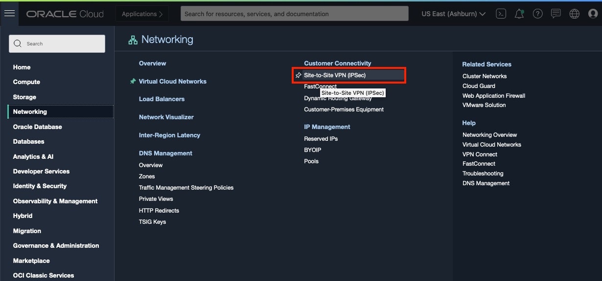
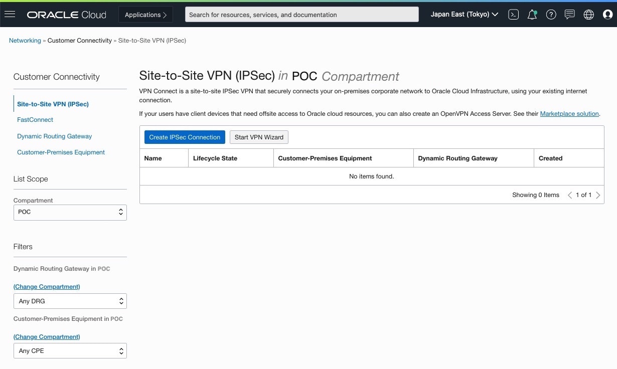
前回設定した Cisco ルーター 841M を使用して、Oracle Cloud Infrastructure (OCI) へ Site-to-Site VPN (IPSec) を IKEv2 (Internet Key Exchange version 2) と BGP(Border Gateway Protocol)を使用して接続してみてみます。
また、2本のTunnelの非対称ルーティングを避けるため、Tunnel1 を優先経路とするよう、AS Path PrependでBGP経路制御してみます。
■ 構成図

IPSec VPN Connection を作成すると、冗長用途でVPN接続は2つの IPSecトンネルで構成され、各トンネル異なるOracleルーターに自動的にプロビジョニングされます。そのためCISCOルーターに2つの IPSec Tunnelを構成します。
● 設定値
ルーターの設定は、CISCO社により検証されたコンフィグを参考として使用します。
・参考: CPE Configuration: Cisco IOS
パラメーターは、構成図を参考にRouterへ設定する値を表にしておきます
| パラメーター | 値 | 説明 |
|---|---|---|
| ${bgpASN} | 65000 | CPE BGP ASN |
| ${cpeInsideTunnelIpAddress1} | 192.168.254.101/30 | Inside tunnel IP address of CPE for the first tunnel. |
| ${cpeInsideTunnelIpAddress2} | 192.168.254.102/30 | Inside tunnel IP address of CPE for the second tunnel. |
| ${OracleInsideTunnelIpAddress1} | 192.168.254.102/30 | Inside tunnel IP address of Oracle-side for the first tunnel. |
| ${OracleInsideTunnelIpAddress2} | 192.168.254.106/30 | Inside tunnel IP address of Oracle-side for the second tunnel. |
| ${cpePublicIpAddress} | 100.100.100.101 | The public IP address for the CPE. |
| ${oracleHeadend1} | 140.204.100.101 | Oracle public IP endpoint obtained from the Oracle Console. |
| ${oracleHeadend2} | 140.204.100.102 | Oracle public IP endpoint obtained from the Oracle Console. |
| ${sharedSecret1} | password | first tunnel SharedSecret |
| ${sharedSecret2} | password | second tunnel SharedSecret |
| ${onPremCidrNetwork} | 192.168.0.0 | On-premises IP range |
| ${onPremCidrNetmask} | 255.255.255.0 | ON-premises subnet mask |
■ OCI事前準備
VCN、Compute等、事前に設定しておきます。今回は、DRG,IPSec Connectionの設定して疎通確認します。
■ Dynamic Routing Gateways (DRG)作成
-
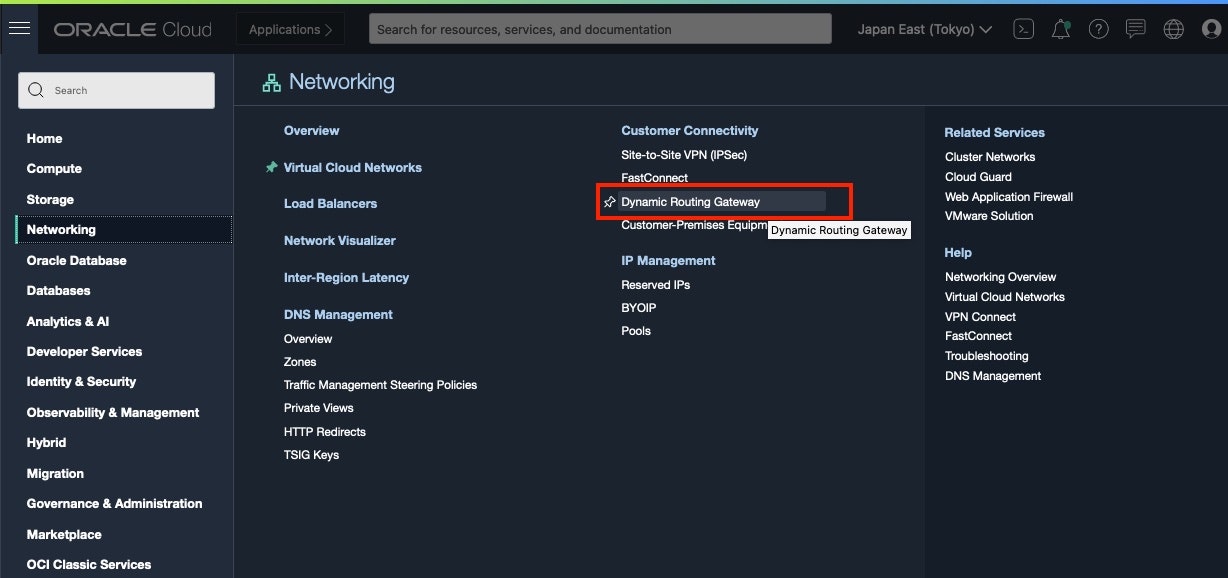
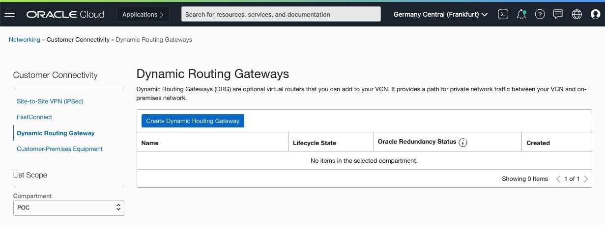
Dynamic Routing Gateways画面
[Create Dynamic Routing Gateway]をクリック
-
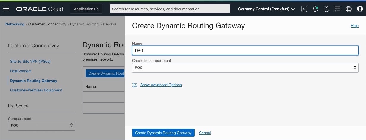
Dynamic Routing Gatewaysの作成画面
以下項目を設定し、[Create Dynamic Routing Gateway]をクリックして作成・Name: 任意の名前
■ VCN - DRG接続
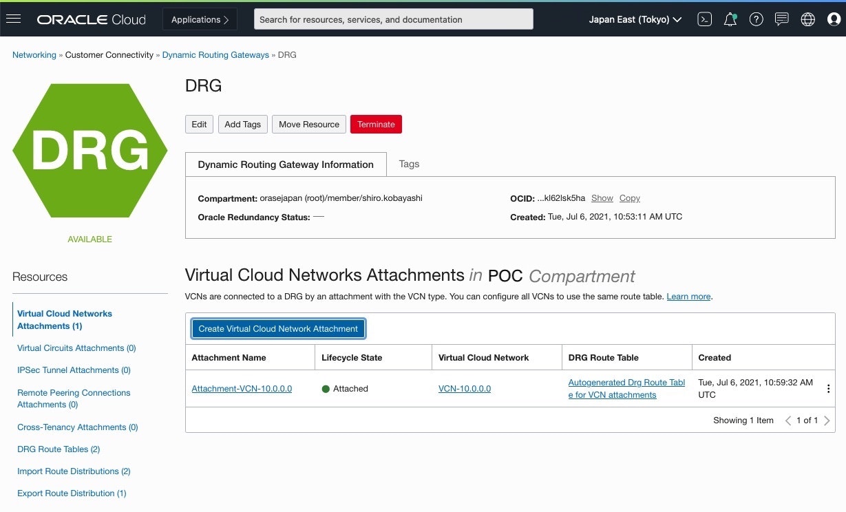
作成したDRGへVCNをAttachします
-
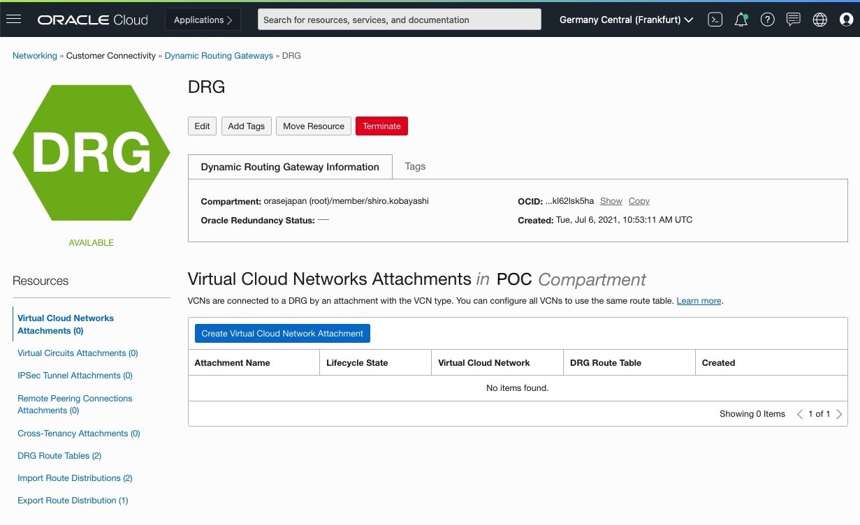
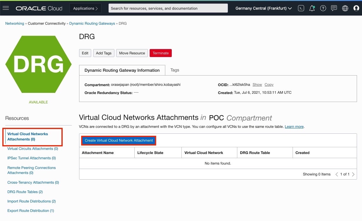
DRG: Virtual Cloud Networks Attachments画面
作成したDRG画面 > Resources > Virtual Cloud Networks Attachmentsをクリックし、
[Virtual Cloud Networks Attachments]をクリック
-
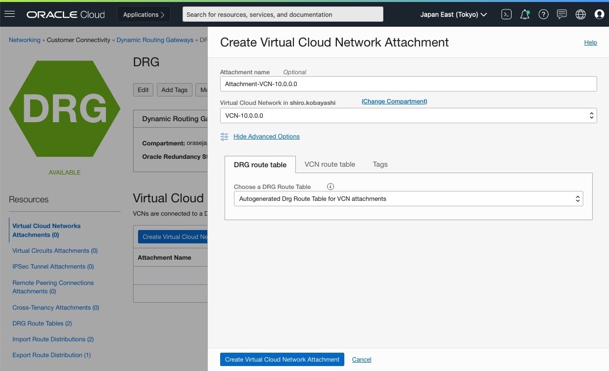
Create Virtual Cloud Network Attachment画面
以下項目を設定し、[Create Virtual Cloud Network Attachment]をクリックして作成
・Attachment name: 任意の名前
■ CPE Object(顧客構内機器)作成
-
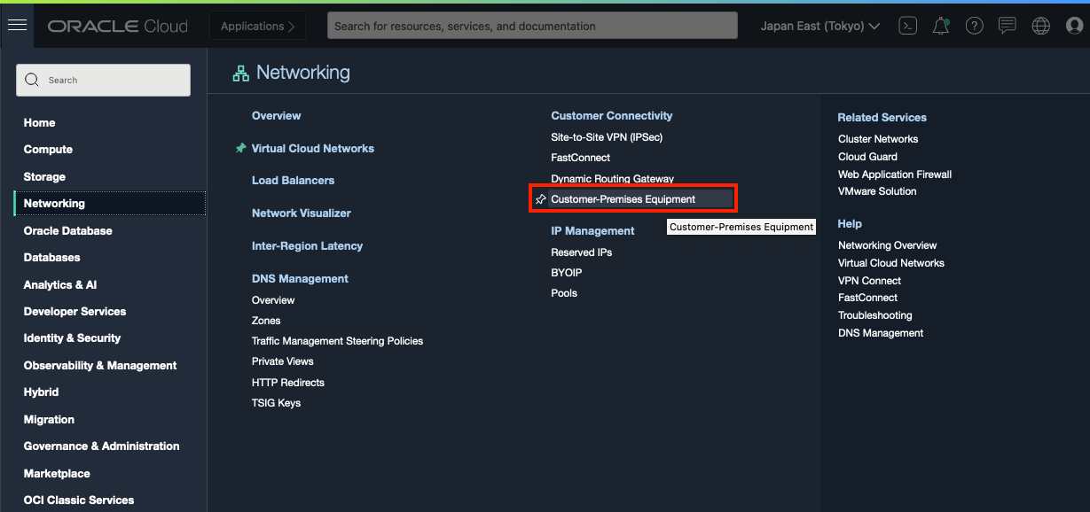
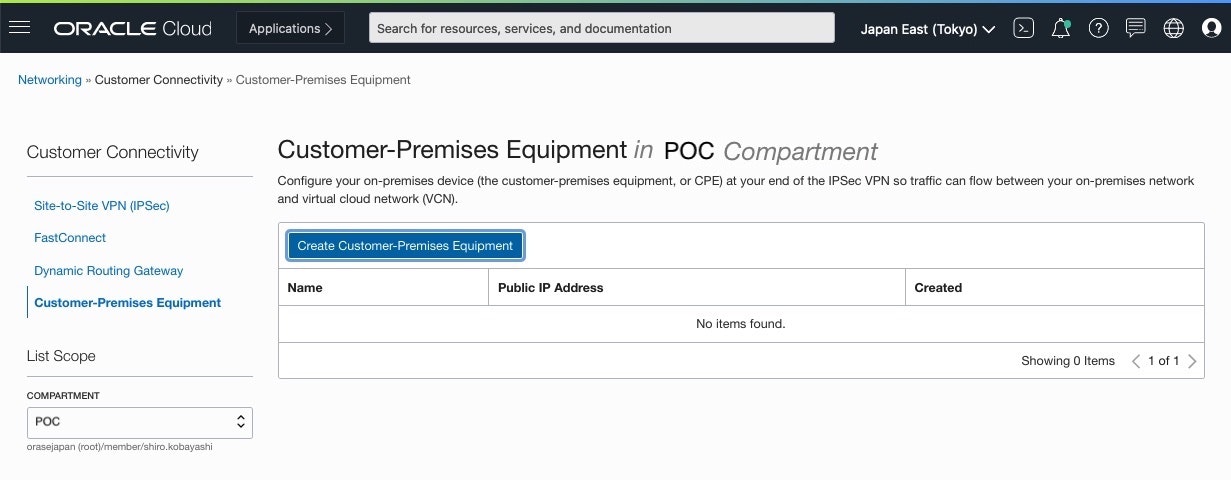
Customer-Premises Equipment画面
[Create Customer-Premises Equipment]をクリック
-
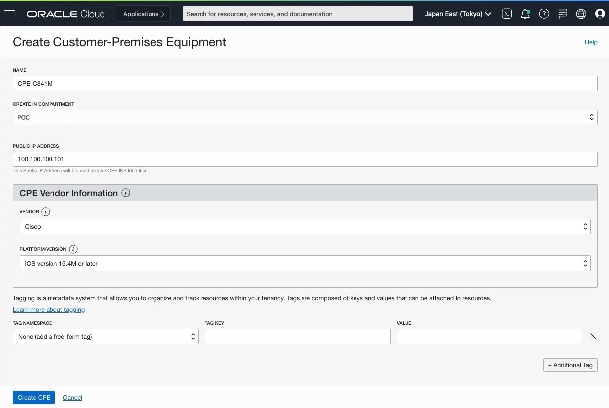
Create Customer-Premises Equipment画面
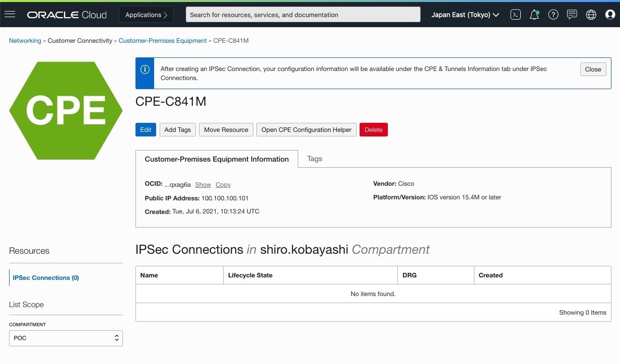
以下入力を行い、[Create CPE]をクリックして作成・Name: 任意の名前
・Public IP Address: CPEの Public IP Address
・Vendor: CPE Vendorを選択
・Platform/Version: CPE Versionを選択
■ IPSec Connection作成
-
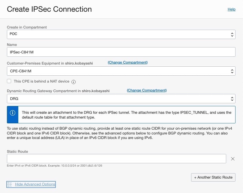
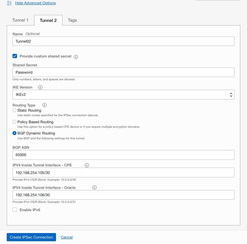
Create IPSec Connection画面
以下入力を行い、[Create IPSec Connection]をクリックして作成
・ IPSec情報
・Name: 任意の名前
・Customer-Premises Equipment: 作成した CPE Objectを設定
・Dynamic Routing Gateway Compartment: 作成した DRGを設定
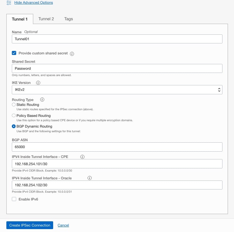
・ Tunnel1 BGP 情報
・Name: 任意の名前
・Shared Secret: 作成した CPE Objectを設定
・IKE Version: 作成した DRGを設定
・Routing Type: BGPを選択
・BGP ASN: BGPの ASNを設定
・IPV4 Inside Tunnel Interface - CPE: CPE側 BGP Peer IPを設定
・IPV4 Inside Tunnel Interface - Oracle: OCI側 BGP Peer IPを設定
・ Tunnel2 BGP 情報
Tunnel1 BGPと同様に設定
-
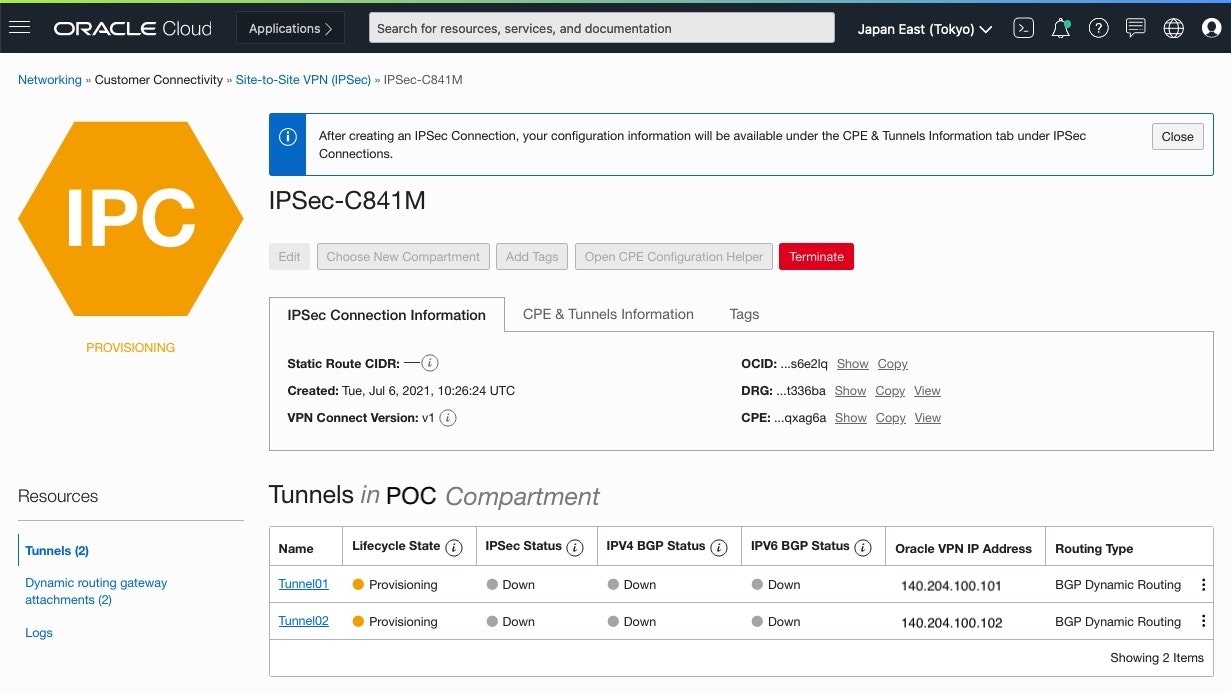
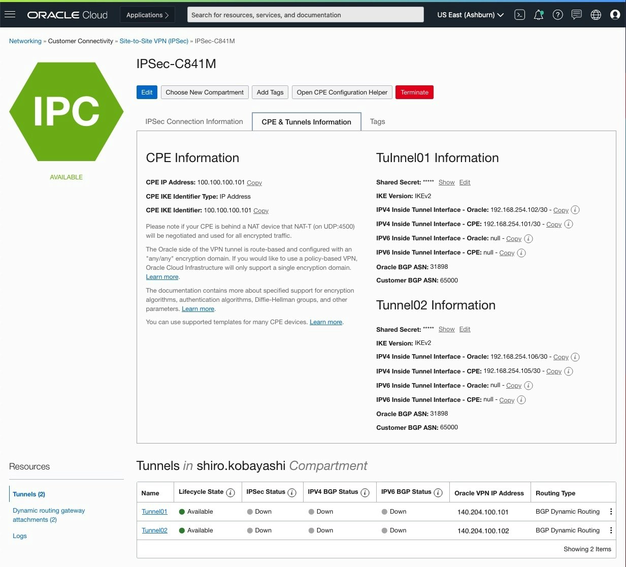
IPSec Connection情報確認
IPSec Connection 作成すると 2つのTunnel用に2つのPublic IPが付与され、このIPを使用して,Cisco Routerを設定します
Cisco RouterとDRG間のIPSec接続が確立されるまで、画面上の Statusは "Down"になります
■ DRG Route Distribution Statements設定
DRGに接続された Attachments(VCN,VPN,FastConnect,RPC等) の Route 制御を行います。
デフォルトでは、DRG へ Import/Export される Route はすべて通す設定(Match All)がされていますので、今回はそのデフォルト値を使用します。
通したくないAttachmentsがある場合は、個別に設定します。
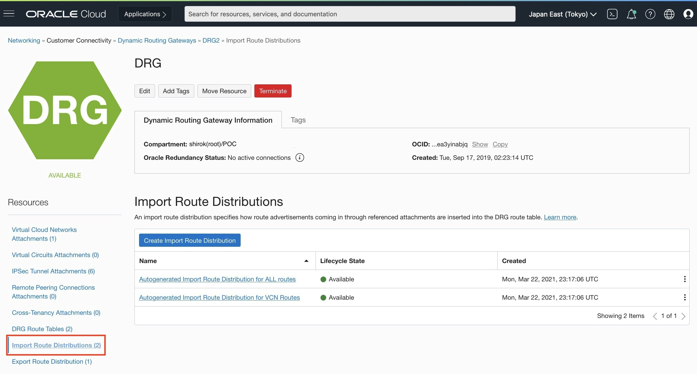
● DRG: Import Route Distributions画面
VCN attachments用とそれ以外用(RPC, VC, IPSec attachments)にデフォルトで以下2つの設定がされていることを確認
-
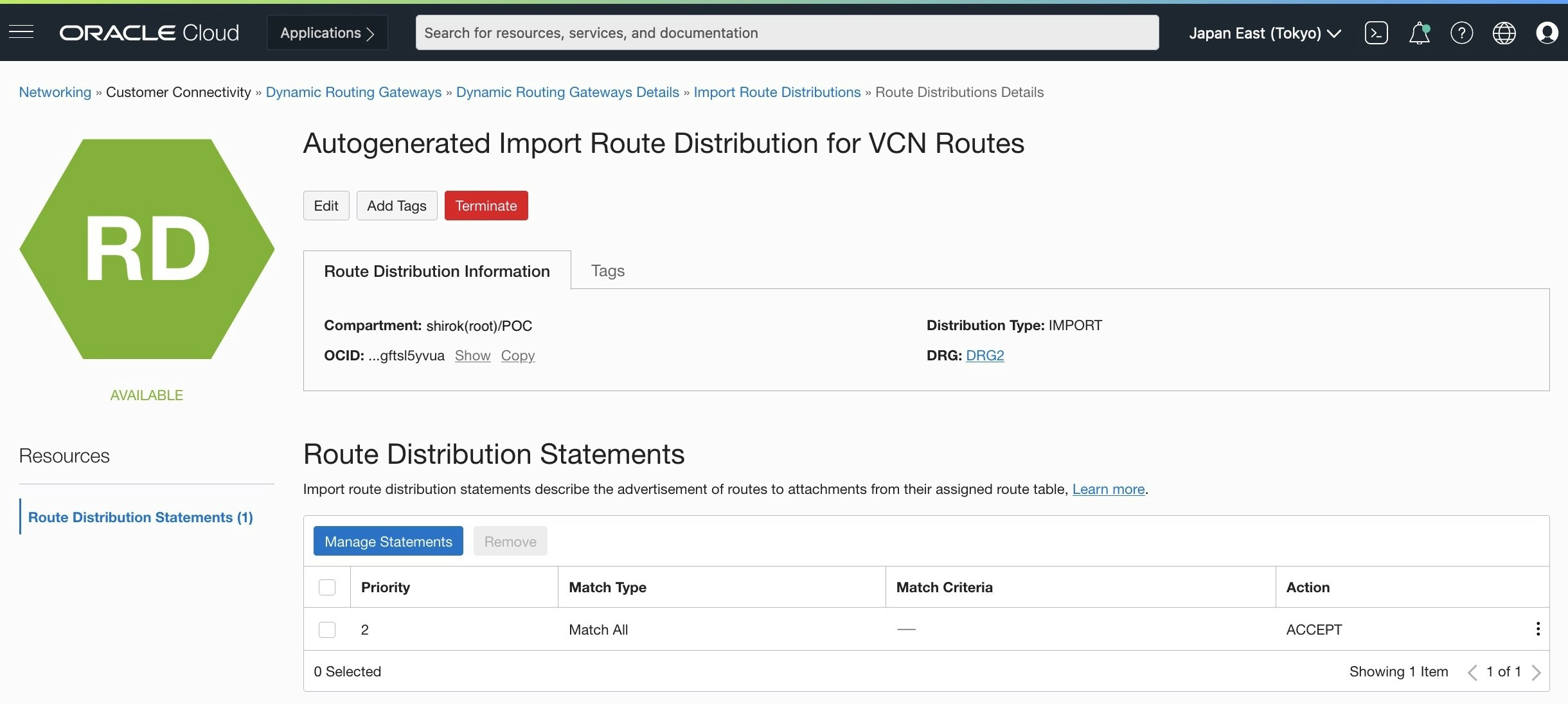
Autogenerated Import Route Distribution for ALL routes確認
デフォルトでは、Match Type が Match ALLで設定
-
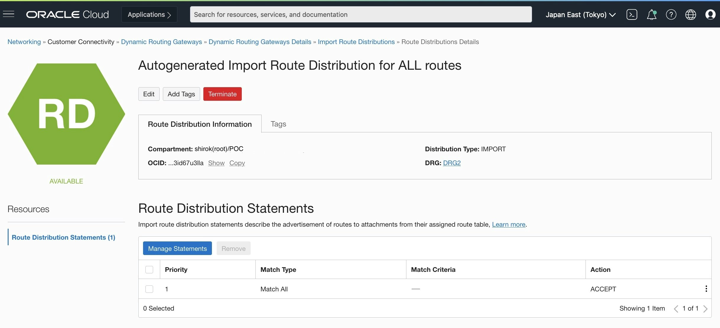
Autogenerated Import Route Distribution for VCN Routes
デフォルトでは、Match Type が Match ALLで設定
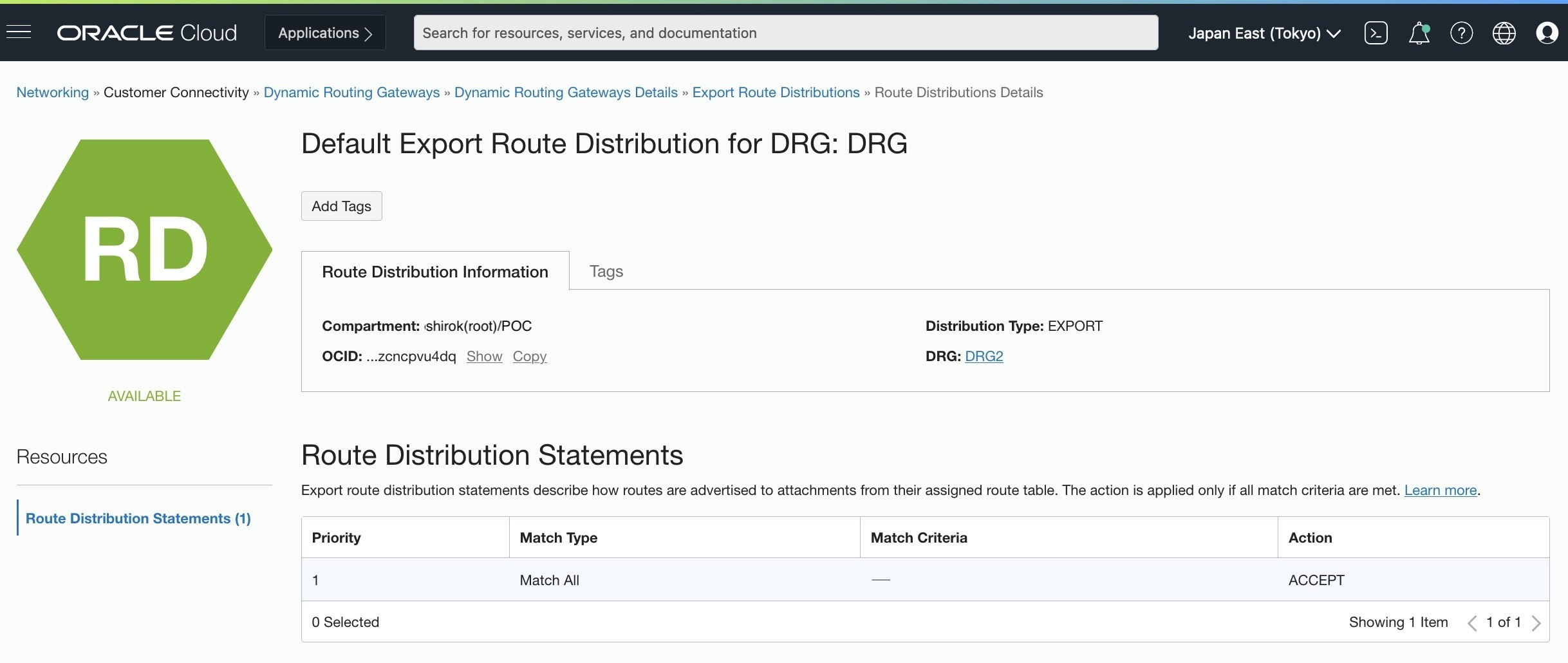
● DRG: Export Route Distributions
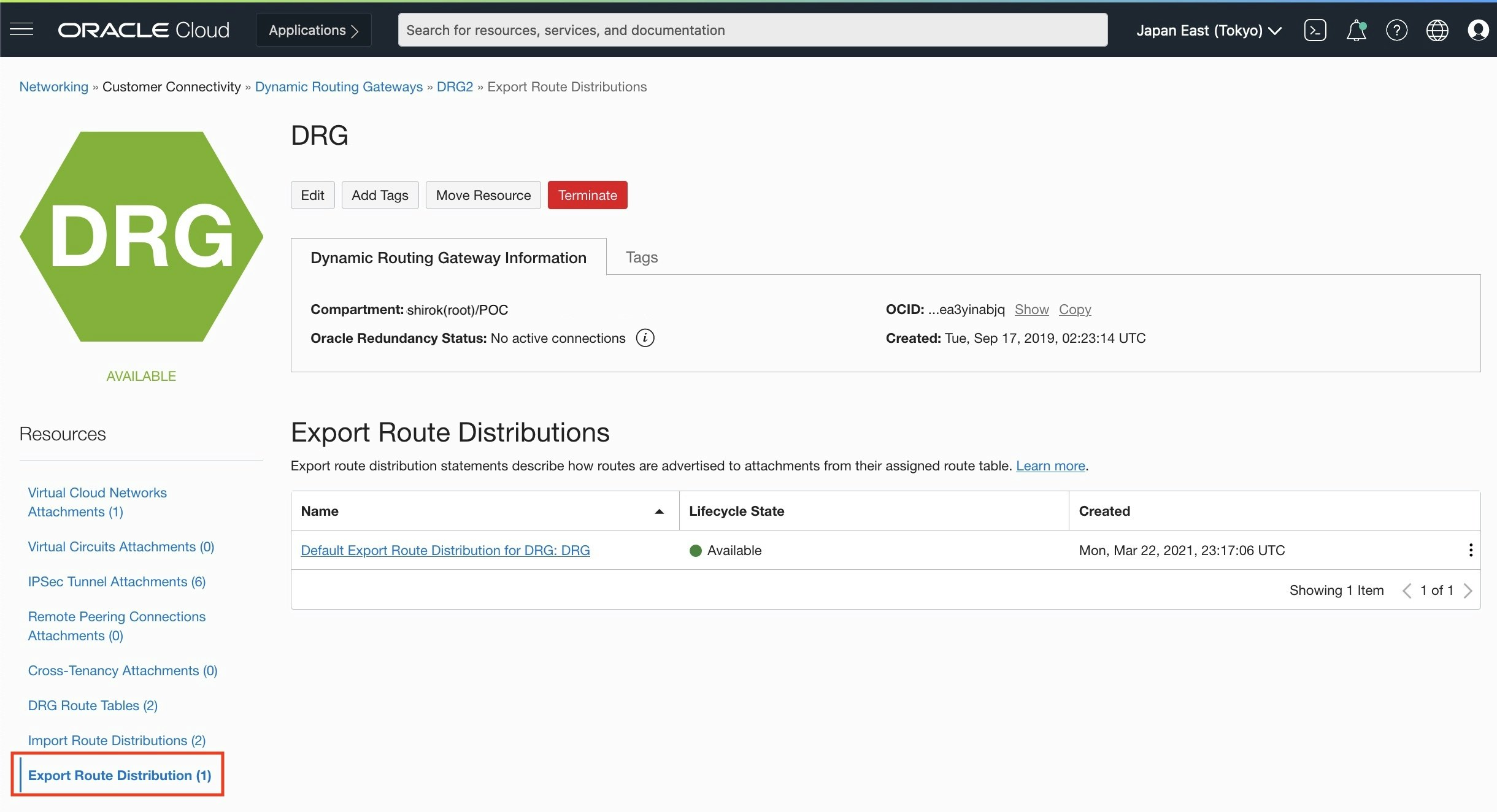
デフォルトで以下1つの Export Route Distributions 設定がされていることを確認
■ OCI Route Table設定
今回 VCNだけでなく、Region内にある Object Storgeなど Oracle Services Network (OSN)に配置されたサービスも IPSecを通してオンプレミスから接続できるように、以前の記事を参考にルート表を設定します
・参考: Transit Routing + IPSec VPN / FastConnectで Object Storage, Autonomous Databaseへ接続してみてみた
■ Cisco Router設定
OCI Documentation のCPE Configurationを参考に作成
● Cisco初期設定
前回設定した記事を参考にCisco 841Mを設定してインターネット接続できることを確認
・参考: Cisco 841M: 初期設定してインターネット接続
● Cisco Router ログイン
	Username: cisco
	Password: ******
	Router>
● グローバル コンフィギュレーション モード開始
	Router>enable
	Router#configure terminal
		Enter configuration commands, one per line.  End with CNTL/Z.
● IPSec 設定
Oracle側では、2つのヘッドエンドが別々のルーターに配置されて冗長性が確保されます。最大の冗長性のためにOracle側でアサインされた2つのTunnelを構成します。
Cisco Systems により検証されたコンフィグ IKEv2構成テンプレートを参考として、Ciscoルーターを構成します
! Keyring (Pre-Shared Key)
crypto ikev2 keyring oracle-vpn-140.204.100.101
 peer oracle_vpn
  address 140.204.100.101
  pre-shared-key local Password01
  pre-shared-key remote Password01

crypto ikev2 keyring oracle-vpn-140.204.100.102
 peer oracle_vpn
  address 140.204.100.102
  pre-shared-key local Password02
  pre-shared-key remote Password02


! IKEv2 and IPSec Policy Configuration
crypto ikev2 proposal oracle_v2_proposal
 encryption aes-cbc-256
 integrity sha384
 group 5

crypto ikev2 policy oracle_v2_policy
 proposal oracle_v2_proposal


! Create an IPSec transform set named 'oracle-vpn-transform' which defines a combination of IPSec (Phase 2) policy options. Specifically, AES256 for encryption and SHA1 for authentication. This is also where tunnel mode is set for IPSec.
! If different parameters are required, modify this template before applying the configuration.

crypto ipsec transform-set oracle-vpn-transform esp-aes 256 esp-sha-hmac
 mode tunnel

! An IPSec profile named 'oracle_v2_ipsec_profile_tunnel#' is created for each tunnel.
crypto ipsec profile oracle_v2_ipsec_profile_tunnel1
 set transform-set oracle-vpn-transform
 set pfs group5
 set security-association lifetime seconds 3600
 set ikev2-profile oracle-vpn-140.204.100.101
!
crypto ipsec profile oracle_v2_ipsec_profile_tunnel2
 set transform-set oracle-vpn-transform
 set pfs group5
 set security-association lifetime seconds 3600
 set ikev2-profile oracle-vpn-140.204.100.102


! IPSec Peers
! Two IKEv2 profiles are created for each Oracle VPN Headend.

crypto ikev2 profile oracle-vpn-140.204.100.101
 match identity remote address 140.204.100.101 255.255.255.255
 identity local address 100.100.100.101
 authentication local pre-share
 authentication remote pre-share
 keyring local oracle-vpn-140.204.100.101
!
crypto ikev2 profile oracle-vpn-140.204.100.102
 match identity remote address 140.204.100.102 255.255.255.255
 identity local address 100.100.100.101
 authentication local pre-share
 authentication remote pre-share
 keyring local oracle-vpn-140.204.100.102


! Virtual Tunnel Interfaces

interface Tunnel1
 ip address 192.168.254.101 255.255.255.252
 ip virtual-reassembly in
 ip tcp adjust-mss 1350
 tunnel source 100.100.100.101
 tunnel mode ipsec ipv4
 tunnel destination 140.204.100.101
 tunnel protection ipsec profile oracle_v2_ipsec_profile_tunnel1
!
interface Tunnel2
 ip address 192.168.254.105 255.255.255.252
 ip virtual-reassembly in
 tunnel source 100.100.100.101
 tunnel mode ipsec ipv4
 tunnel destination 140.204.100.102
 tunnel protection ipsec profile oracle_v2_ipsec_profile_tunnel2
● BGP設定
Routing Protocolは、BGP動的ルーティングと静的ルーティングを使用できます。
今回は、BGPを使います。
BGP最適パス選択アルゴリズムの操作方法に関するOracle推奨など、VPN接続によるルーティングの詳細は、Oracle IPSec VPNのルーティングを参照してください。
! IP Routing
router bgp 65000
 bgp log-neighbor-changes
 neighbor 192.168.254.102 remote-as 31898
 neighbor 192.168.254.106 remote-as 31898
 !
 address-family ipv4
  network 192.168.0.0 mask 255.255.255.0
  neighbor 192.168.254.102 activate
  neighbor 192.168.254.102 soft-reconfiguration inbound
  neighbor 192.168.254.106 activate
  neighbor 192.168.254.106 soft-reconfiguration inbound
 exit-address-family
● Internet Facing Access List設定
! Update Any Internet Facing Access List to Allow IPSec and ISAKMP Packets

! You may need to allow IPSec and ISAKMP packets out your internet facing interface.
! Uncomment below lines to create a new ACL allowing IPSec and ISAKMP traffic and apply it to the outside interface.

ip access-list extended INTERNET-INGRESS
 permit udp host 140.204.100.101 host 100.100.100.101 eq isakmp
 permit esp host 140.204.100.101 host 100.100.100.101
 permit udp host 140.204.100.102 host 100.100.100.101 eq isakmp
 permit esp host 140.204.100.102 host 100.100.100.101
 permit icmp any any echo
 permit icmp any any echo-reply
 permit icmp any any unreachable

 interface ${outsideInterface}
  ip access-group INTERNET-INGRESS in
■ VPN接続確認
● OCI IPSec Connection画面確認
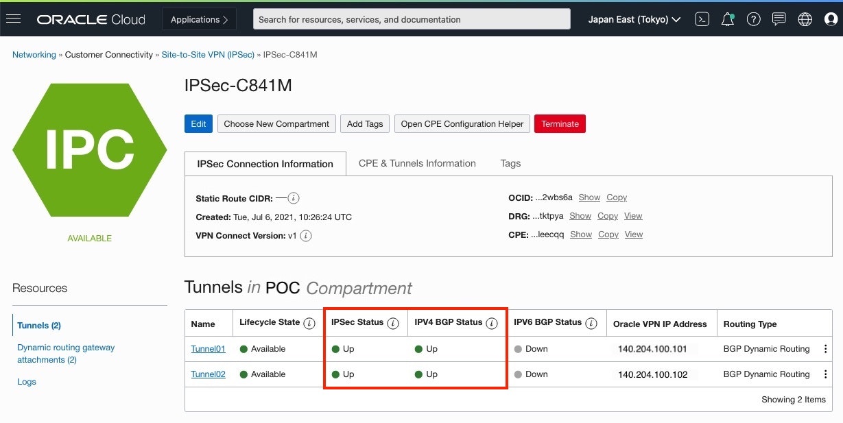
作成したIPSec Connectionの "IPSec Status"と "IPV4 BGP Status"が UPしていることを確認
● CISCO Router確認
・ IPSec SA確立確認
Router# show crypto session
Crypto session current status

Interface: Tunnel1
Profile: oracle-vpn-140.204.100.101
Session status: UP-ACTIVE
Peer: 140.204.100.101 port 500
  Session ID: 1125
  IKEv2 SA: local 100.100.100.101/500 remote 140.204.100.101/500 Active
  IPSEC FLOW: permit ip 0.0.0.0/0.0.0.0 0.0.0.0/0.0.0.0
        Active SAs: 2, origin: crypto map

Interface: Tunnel2
Profile: oracle-vpn-140.204.100.102
Session status: UP-ACTIVE
Peer: 140.204.100.102 port 500
  Session ID: 1138
  IKEv2 SA: local 100.100.100.101/500 remote 140.204.100.102/500 Active
  IPSEC FLOW: permit ip 0.0.0.0/0.0.0.0 0.0.0.0/0.0.0.0
        Active SAs: 2, origin: crypto map
・ IPSec 暗号化マップ確認
Router# show crypto map
        Interfaces using crypto map NiStTeSt1:

Crypto Map: "Tunnel1-head-0" IKEv2 profile: oracle-vpn-140.204.100.101

Crypto Map IPv4 "Tunnel1-head-0" 65536 ipsec-isakmp
        IKEv2 Profile: oracle-vpn-140.204.100.101
        Profile name: oracle_ipsec_profile_Tunnel1
        Security association lifetime: 4608000 kilobytes/3600 seconds
        Responder-Only (Y/N): N
        PFS (Y/N): Y
        DH group:  group5
        Mixed-mode : Disabled
        Transform sets={
                oracle-vpn-transform:  { esp-256-aes esp-sha-hmac  } ,
        }

Crypto Map IPv4 "Tunnel1-head-0" 65537 ipsec-isakmp
        Map is a PROFILE INSTANCE.
        Peer = 140.204.100.101
        IKEv2 Profile: oracle-vpn-140.204.100.101
        Extended IP access list
            access-list  permit ip any any
        Current peer: 140.204.100.101
        Security association lifetime: 4608000 kilobytes/3600 seconds
        Responder-Only (Y/N): N
        PFS (Y/N): Y
        DH group:  group5
        Mixed-mode : Disabled
        Transform sets={
                oracle-vpn-transform:  { esp-256-aes esp-sha-hmac  } ,
        }
        Always create SAs
        Interfaces using crypto map Tunnel1-head-0:
                Tunnel1


Crypto Map: "Tunnel2-head-0" IKEv2 profile: oracle-vpn-140.204.100.102

Crypto Map IPv4 "Tunnel2-head-0" 65536 ipsec-isakmp
        IKEv2 Profile: oracle-vpn-140.204.100.102
        Profile name: oracle_ipsec_profile_Tunnel2
        Security association lifetime: 4608000 kilobytes/3600 seconds
        Responder-Only (Y/N): N
        PFS (Y/N): Y
        DH group:  group5
        Mixed-mode : Disabled
        Transform sets={
                oracle-vpn-transform:  { esp-256-aes esp-sha-hmac  } ,
        }

Crypto Map IPv4 "Tunnel2-head-0" 65537 ipsec-isakmp
        Map is a PROFILE INSTANCE.
        Peer = 140.204.100.102
        IKEv2 Profile: oracle-vpn-140.204.100.102
        Extended IP access list
            access-list  permit ip any any
        Current peer: 140.204.100.102
        Security association lifetime: 4608000 kilobytes/3600 seconds
        Responder-Only (Y/N): N
        PFS (Y/N): Y
        DH group:  group5
        Mixed-mode : Disabled
        Transform sets={
                oracle-vpn-transform:  { esp-256-aes esp-sha-hmac  } ,
        }
        Always create SAs
        Interfaces using crypto map Tunnel2-head-0:
                Tunnel2
・ BGP UP確認
Router#show ip bgp summary
      BGP router identifier 192.168.254.105, local AS number 65000
      BGP table version is 20, main routing table version 20
      10 network entries using 1440 bytes of memory
      19 path entries using 1520 bytes of memory
      2/2 BGP path/bestpath attribute entries using 320 bytes of memory
      1 BGP AS-PATH entries using 24 bytes of memory
      0 BGP route-map cache entries using 0 bytes of memory
      0 BGP filter-list cache entries using 0 bytes of memory
      BGP using 3304 total bytes of memory
      BGP activity 10/0 prefixes, 37/18 paths, scan interval 60 secs

      Neighbor        V           AS MsgRcvd MsgSent   TblVer  InQ OutQ Up/Down  State/PfxRcd
      192.168.254.102 4        31898      16      19       20    0    0 00:11:31        9
      192.168.254.106 4        31898      19      23       20    0    0 00:15:09        9
・ BGP Neighbors Received-routes確認
OCIから受信した Routeを確認します。
今回、Tokyo Regionの OSN と VCNのSubnetのRoute情報が、OCIからCiscoルーターへ送信されていることを確認
Object Storage,ADB等のVCN外のサービスがあるOracle Services Network(OSN)のIP Address Rangesは、[VCNおよびOracle Services Network用のパブリックIPアドレス]の JSONファイルにある"OSN"と"OBJECT_STORAGE"項目部分のCIDRです。
Router#show ip bgp neighbors 192.168.254.102 received-routes
      BGP table version is 20, local router ID is 192.168.254.105
      Status codes: s suppressed, d damped, h history, * valid, > best, i - internal,
                  r RIB-failure, S Stale, m multipath, b backup-path, f RT-Filter,
                  x best-external, a additional-path, c RIB-compressed,
      Origin codes: i - IGP, e - EGP, ? - incomplete
      RPKI validation codes: V valid, I invalid, N Not found

      Network          Next Hop            Metric LocPrf Weight Path
      *>  10.0.0.0/24      192.168.254.102                        0 31898 i
      *>  134.70.80.0/23   192.168.254.102                        0 31898 i
      *>  134.70.82.0/23   192.168.254.102                        0 31898 i
      *>  140.91.32.0/23   192.168.254.102                        0 31898 i
      *>  140.204.8.128/25 192.168.254.102                        0 31898 i
      *>  192.29.36.0/22   192.168.254.102                        0 31898 i
      *>  192.29.40.0/22   192.168.254.102                        0 31898 i
      *>  192.29.44.0/25   192.168.254.102                        0 31898 i

      Total number of prefixes 9
・ BGP Neighbors Advertised-routes確認
OCI にアドバタイズされたルートを確認
Router#show ip bgp neighbors 192.168.254.102 advertised-routes
    BGP table version is 14, local router ID is 192.168.254.105
    Status codes: s suppressed, d damped, h history, * valid, > best, i - internal,
                r RIB-failure, S Stale, m multipath, b backup-path, f RT-Filter,
                x best-external, a additional-path, c RIB-compressed,
    Origin codes: i - IGP, e - EGP, ? - incomplete
    RPKI validation codes: V valid, I invalid, N Not found

        Network          Next Hop            Metric LocPrf Weight Path
        *>  10.0.0.0/24      192.168.254.102                        0 31898 i
        *>  134.70.80.0/23   192.168.254.102                        0 31898 i
        *>  134.70.82.0/23   192.168.254.102                        0 31898 i
        *>  140.91.32.0/23   192.168.254.102                        0 31898 i
        *>  140.204.8.128/25 192.168.254.102                        0 31898 i
        *>  192.29.36.0/22   192.168.254.102                        0 31898 i
        *>  192.29.40.0/22   192.168.254.102                        0 31898 i
        *>  192.29.44.0/25   192.168.254.102                        0 31898 i
        *>  192.168.0.0/24   0.0.0.0                                0 32768 i
・Router の Route情報確認
Router#show ip route
	Codes: L - local, C - connected, S - static, R - RIP, M - mobile, B - BGP
		D - EIGRP, EX - EIGRP external, O - OSPF, IA - OSPF inter area
		N1 - OSPF NSSA external type 1, N2 - OSPF NSSA external type 2
		E1 - OSPF external type 1, E2 - OSPF external type 2
		i - IS-IS, su - IS-IS summary, L1 - IS-IS level-1, L2 - IS-IS level-2
		ia - IS-IS inter area, * - candidate default, U - per-user static route
		o - ODR, P - periodic downloaded static route, H - NHRP, l - LISP
		a - application route
		+ - replicated route, % - next hop override, p - overrides from PfR

	Gateway of last resort is 0.0.0.0 to network 0.0.0.0

	S*    0.0.0.0/0 is directly connected, Dialer1
		10.0.0.0/24 is subnetted, 2 subnets
	B        10.0.0.0 [20/0] via 192.168.254.102, 00:02:59
		100.0.0.0/32 is subnetted, 1 subnets
	C        100.100.100.101 is directly connected, Dialer1
		134.70.0.0/23 is subnetted, 2 subnets
	B        134.70.80.0 [20/0] via 192.168.254.102, 00:02:59
	B        134.70.82.0 [20/0] via 192.168.254.102, 00:02:59
		140.91.0.0/23 is subnetted, 1 subnets
	B        140.91.32.0 [20/0] via 192.168.254.102, 00:02:59
		140.204.0.0/25 is subnetted, 1 subnets
	B        140.204.8.128 [20/0] via 192.168.254.102, 00:02:59
		163.139.0.0/32 is subnetted, 1 subnets
	C        163.139.100.35 is directly connected, Dialer1
	B     192.29.36.0/22 [20/0] via 192.168.254.102, 00:02:59
	B     192.29.40.0/22 [20/0] via 192.168.254.102, 00:02:59
		192.29.44.0/25 is subnetted, 1 subnets
	B        192.29.44.0 [20/0] via 192.168.254.102, 00:02:59
		192.168.0.0/24 is variably subnetted, 2 subnets, 2 masks
	C        192.168.0.0/24 is directly connected, Vlan1
	L        192.168.0.1/32 is directly connected, Vlan1
		192.168.254.0/24 is variably subnetted, 4 subnets, 2 masks
	C        192.168.254.100/30 is directly connected, Tunnel1
	L        192.168.254.101/32 is directly connected, Tunnel1
	C        192.168.254.104/30 is directly connected, Tunnel2
	L        192.168.254.105/32 is directly connected, Tunnel2
■ Tunnel1優先経路(対象ルーティング)設定
非対称ルーティングを避けるため、双方向(OCI->CPE, CPE->OCI)が Tunnel1 を優先経路とするよう、CiscoルーターのBGP設定 AS_PATHプリペンドと WEIGHTアトリビュート (もしくはLocal-Preference等)を必要に応じて設定
今回は、対象ルーティングになるよう設定してみてみます
● DRG Route 確認
-
DRG画面
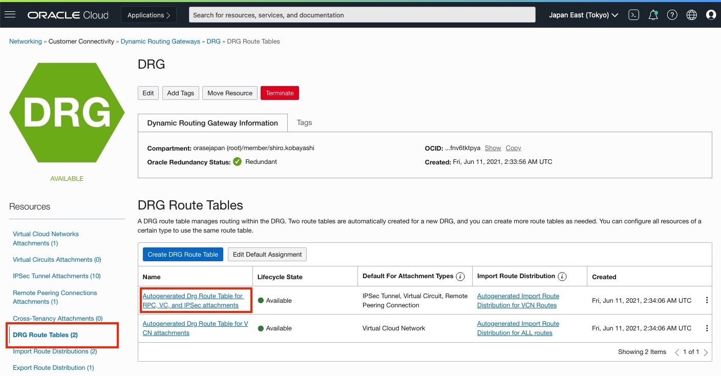
Resources > DRG Route Tables をクリックし、DRG Route Tables にある IPSec attachmentsのRoute Tableをクリック
-
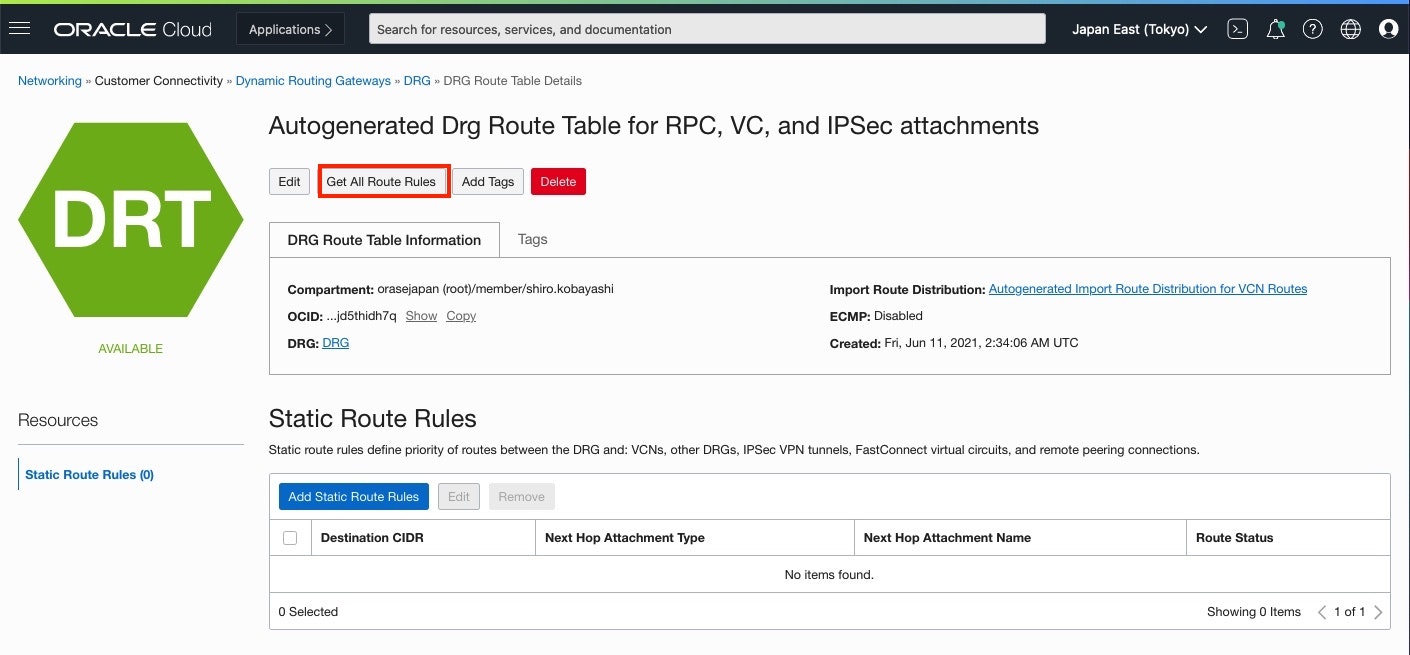
Drg Route Table for IPSec attachments 画面
[Get All ROute Roules]をクリック
-
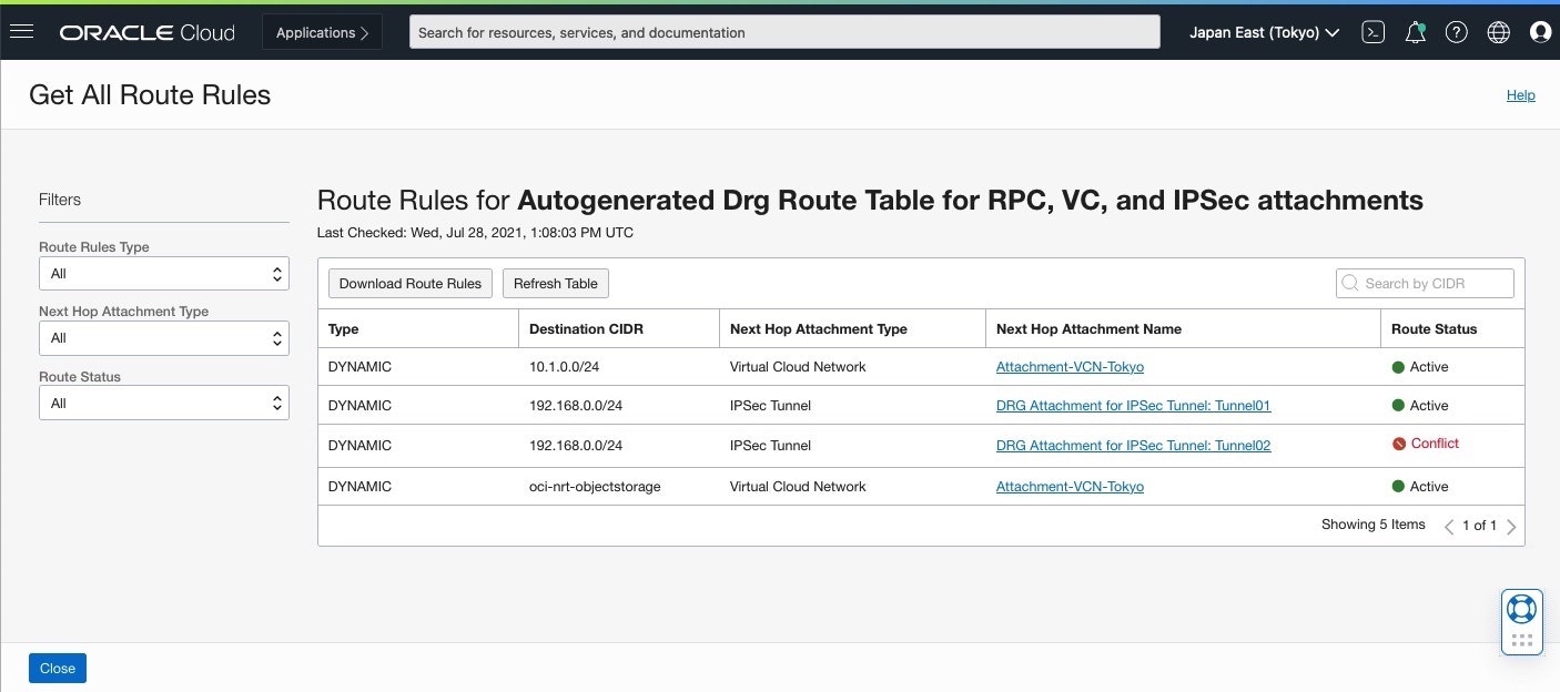
Get All Route Rules 画面
DRG Route Rules 情報では、Tunnel2 が Active であり Tunnel01 が Conflict Stutas でActive
で使用されておらず、Standby経路となっていて、Cisco の show ip route 情報では、192.168.254.102 の Tunnel1 が使用されているため、非対称ルーティングであることが確認できます。

● AS_PATH Prepend 設定 (OCI -> Cisco経路)
AS_PATHアトリビュートは、Route-Mapの設定で、自身の AS番号に AS番号を追加することによって EBGPピアに ASパスを長く見せることができます。
この機能はAS_PATHプリペンドと言い、このコマンドで指定したAS番号は、AS_PATHの先頭に追加されASパスを長くすることができます。
・AS_PATHプリペンドの設定
 (config)# route-map map-tag permit | deny [ seq-number ]
 (config-route-map)# match condition
 (config-route-map)# set as-path prepend as-number [ as-number ]
・設定実行
PRE-AS に合致するルートの AS_PATHに、AS番号65000 を 2つ追加
ip prefix-list PRE-AS permit 192.168.0.0/24

route-map R-ASPRE permit 10
 match ip address prefix-list PRE-AS
 set as-path prepend 65000 65000
route-map R-ASPRE permit 20

router bgp 65000
  neighbor 192.168.254.106 route-map R-ASPRE out
● Weight Attribute(Cisco -> OCI経路)
WEIGHTアトリビュートは、CIsco 独自の BGPアトリビュートであり、ベストパス選択のアルゴリズム比較の最初に使用されるアトリビュートで WEIGHT値が最大のルートが優先されます。
1台の BGPルータのASから出力されるパス(Route)が複数ある場合などで WEIGHTアトリビュートを使用します
他メーカーのルーターでは、Local-Preference等を使用します
- WEIGHTアトリビュート - 設定
Tunnel1(192.168.254.102)側のWEIGHTを200、Tunnel2(192.168.254.106)側のWEIGHTを100設定し、Tunnel1を優先経路へ設定
router bgp 65000
  neighbor 192.168.254.102 weight 200
  neighbor 192.168.254.106 weight 100
● Route情報確認
1) Ciscoルーター Route確認
・show ip bgp
OCI の ASN#31898 に対してWeight列に設定した WEIGHTアトリビュート値 200と 100が設定されていることを確認
Router#show ip bgp
	BGP table version is 32, local router ID is 192.168.254.105
	Status codes: s suppressed, d damped, h history, * valid, > best, i - internal,
				r RIB-failure, S Stale, m multipath, b backup-path, f RT-Filter,
				x best-external, a additional-path, c RIB-compressed,
	Origin codes: i - IGP, e - EGP, ? - incomplete
	RPKI validation codes: V valid, I invalid, N Not found

		Network          Next Hop            Metric LocPrf Weight Path
	*>  10.1.0.0/24      192.168.254.102                      200 31898 i
	*                    192.168.254.106                      100 31898 i
	*>  134.70.80.0/23   192.168.254.102                      200 31898 i
	*                    192.168.254.106                      100 31898 i
	*>  134.70.82.0/23   192.168.254.102                      200 31898 i
	*                    192.168.254.106                      100 31898 i
	*>  140.91.32.0/23   192.168.254.102                      200 31898 i
	*                    192.168.254.106                      100 31898 i
	*>  140.204.8.128/25 192.168.254.102                      200 31898 i
	*                    192.168.254.106                      100 31898 i
	*>  192.29.36.0/22   192.168.254.102                      200 31898 i
	*                    192.168.254.106                      100 31898 i
	*>  192.29.40.0/22   192.168.254.102                      200 31898 i
	*                    192.168.254.106                      100 31898 i
	*>  192.29.44.0/25   192.168.254.102                      200 31898 i
	*                    192.168.254.106                      100 31898 i
	*>  192.168.0.0/24 0.0.0.0                  0         32768 i
・show ip route
OCIへの Route は、192.168.254.102 の Tunnel1 が使用されていることを確認
Router#show ip route
	Codes: L - local, C - connected, S - static, R - RIP, M - mobile, B - BGP
		D - EIGRP, EX - EIGRP external, O - OSPF, IA - OSPF inter area
		N1 - OSPF NSSA external type 1, N2 - OSPF NSSA external type 2
		E1 - OSPF external type 1, E2 - OSPF external type 2
		i - IS-IS, su - IS-IS summary, L1 - IS-IS level-1, L2 - IS-IS level-2
		ia - IS-IS inter area, * - candidate default, U - per-user static route
		o - ODR, P - periodic downloaded static route, H - NHRP, l - LISP
		a - application route
		+ - replicated route, % - next hop override, p - overrides from PfR

	Gateway of last resort is 0.0.0.0 to network 0.0.0.0

	S*    0.0.0.0/0 is directly connected, Dialer1
		10.0.0.0/24 is subnetted, 2 subnets
	B        10.1.0.0 [20/0] via 192.168.254.102, 00:12:22
		100.0.0.0/32 is subnetted, 1 subnets
	C        100.100.100.101 is directly connected, Dialer1
		134.70.0.0/23 is subnetted, 2 subnets
	B        134.70.80.0 [20/0] via 192.168.254.102, 00:12:22
	B        134.70.82.0 [20/0] via 192.168.254.102, 00:12:22
		140.91.0.0/23 is subnetted, 1 subnets
	B        140.91.32.0 [20/0] via 192.168.254.102, 00:01:19
		140.204.0.0/25 is subnetted, 1 subnets
	B        140.204.8.128 [20/0] via 192.168.254.102, 00:01:19
		163.139.0.0/32 is subnetted, 1 subnets
	C        163.139.100.35 is directly connected, Dialer1
	B     192.29.36.0/22 [20/0] via 192.168.254.102, 00:01:19
	B     192.29.40.0/22 [20/0] via 192.168.254.102, 00:01:19
		192.29.44.0/25 is subnetted, 1 subnets
	B        192.29.44.0 [20/0] via 192.168.254.102, 00:01:19
		192.168.0.0/24 is variably subnetted, 2 subnets, 2 masks
	C        192.168.0.0/24 is directly connected, Vlan1
	L        192.168.0.1/32 is directly connected, Vlan1
		192.168.254.0/24 is variably subnetted, 4 subnets, 2 masks
	C        192.168.254.100/30 is directly connected, Tunnel1
	L        192.168.254.101/32 is directly connected, Tunnel1
	C        192.168.254.104/30 is directly connected, Tunnel2
	L        192.168.254.105/32 is directly connected, Tunnel2
2) DRG Route確認
優先設定が有効化され、Tunnel01 が Activeに変わり、対象ルーティングになったことを確認
■ 接続確認
● On-Premises -> OCI Compute Instance接続確認
・Trace Route確認
onp-inst01:~ user$ traceroute -I 10.0.0.2
	traceroute to 10.0.0.2 (10.0.0.2), 64 hops max, 72 byte packets
	1  * * *
	2  * * *
	3  10.0.0.2 (10.0.0.2)  6.555 ms  6.708 ms  7.079 ms
・Ping疎通確認
onp-inst01:~ user$ ping 10.0.0.2 -c 3
	PING 10.0.0.2 (10.0.0.2): 56 data bytes
	64 bytes from 10.0.0.2: icmp_seq=0 ttl=62 time=6.940 ms
	64 bytes from 10.0.0.2: icmp_seq=1 ttl=62 time=6.780 ms
	64 bytes from 10.0.0.2: icmp_seq=2 ttl=62 time=5.916 ms

	--- 10.0.0.2 ping statistics ---
	3 packets transmitted, 3 packets received, 0.0% packet loss
	round-trip min/avg/max/stddev = 5.916/6.545/6.940/0.450 ms
・ssh接続確認
onp-inst01:~ user$ ssh -i id_rsa opc@10.0.0.2 hostname
	tokyo-inst
● On-Premises -> OCI Object Storage接続確認
・Trace Route確認
onp-inst01:~ user$ traceroute -I objectstorage.ap-Tokyo-1.oraclecloud.com
	traceroute to objectstorage.ap-tokyo-1.oci.oraclecloud.com (134.70.80.3), 64 hops max, 72 byte packets
	1  * * *
	2  * * *
	3  objectstorage.ap-tokyo-1.oci.oraclecloud.com (134.70.80.3)  11.819 ms  10.322 ms  12.619 ms
・Ping疎通確認
onp-inst01:~ user$ ping objectstorage.ap-Tokyo-1.oraclecloud.com -c 3
	PING objectstorage.ap-tokyo-1.oci.oraclecloud.com (134.70.80.3): 56 data bytes
	64 bytes from 134.70.80.3: icmp_seq=0 ttl=62 time=10.229 ms
	64 bytes from 134.70.80.3: icmp_seq=1 ttl=62 time=6.742 ms
	64 bytes from 134.70.80.3: icmp_seq=2 ttl=62 time=6.178 ms

	--- objectstorage.ap-tokyo-1.oci.oraclecloud.com ping statistics ---
	3 packets transmitted, 3 packets received, 0.0% packet loss
	round-trip min/avg/max/stddev = 6.178/7.716/10.229/1.792 ms
■ 設定保存
設定を保存するには、次のコマンドを使用して startup-config に実行 unning-config を保存
	Router#copy running-config startup-config
		Destination filename [startup-config]?
		Building configuration...
		[OK]
■ 参考
● OCI Documents
・CPE Configuration
・CPE Configuration: Cisco IOS
・Connectivity Redundancy Guide
● CIsco Documents
・Cisco 841M J シリーズ
・Cisco 841M ドキュメント
・Cisco 800M データシート
・Cisco Start ユーザ サイトファームウェア ダウンロード
・BGPルートがアドバタイズされない場合のトラブルシューティング
● infraexpert.com
・BGP AS_PATH - Cisco Config
・route-map - redistribute
・BGP WEIGHT - Cisco Config
