XBeeを使った自宅状態遠隔見守りサービス実現方法の紹介
第5章 ESP32-WROVER-E開発ボードのツール設定と接続を解説します。
Arduino IDE のインストールと設定
Arduino IDE のインストール
ESP32マイコンはArduino IDEで行います。
Arduino IDEをダウンロードしてインストールします。
ESP32用ライブラリのインストール

👆FileメニューのPreferencesを開きます。

👆Additional boards manager URLsに以下を入力します。
https://dl.espressif.com/dl/package_esp32_index.json
Board Manager の設定

👆ToolsメニューのBoard-Board Managerを開きます。

👆「esp32 by Espressif Systems」をインストールします。
Driver のインストール
下記リンクからESP32-DevKitC-VE用のDriverをダウンロードしてインストールします。
CP210x USB to UART Bridge VCP Drivers
ESP32の接続と動作確認

👆PCとESP32をUSBで接続します。
USBの形状はMicro USB Type-Bです。

👆デバイスマネージャーでシリアルポートを確認します。
USB to UART Bridgeと記載されているポートが対象のポートです。
この例ではCOM7がESP32の接続ポートです。
※ シリアルポートが確認できない場合は、上記Driver のインストールを試してみて下さい。

👆Arduino IDEを起動し、"Tools"-"Board"-"esp32"-"ESP32 Dev Module"を選択します。

👆"Tools"-"Port"-"COM7"を選択します。
※ "COM7"は上記デバイスマネージャーで確認したシリアルポートです。
中央のコード領域に下記コードを貼り付けます。
void setup() {
  Serial.begin(9600);
}

void loop() {
  delay(1000);
  Serial.println("test message...");
}
コード解説としては"setup"関数でシリアルの通信速度を"9600 bps"に設定し
"loop"関数で1000ms待機した後、シリアルに"test message..."と書き込みます。

👆コード領域に上記コードを貼り付けたら、左上の「→」"Upload"ボタンをクリックします。
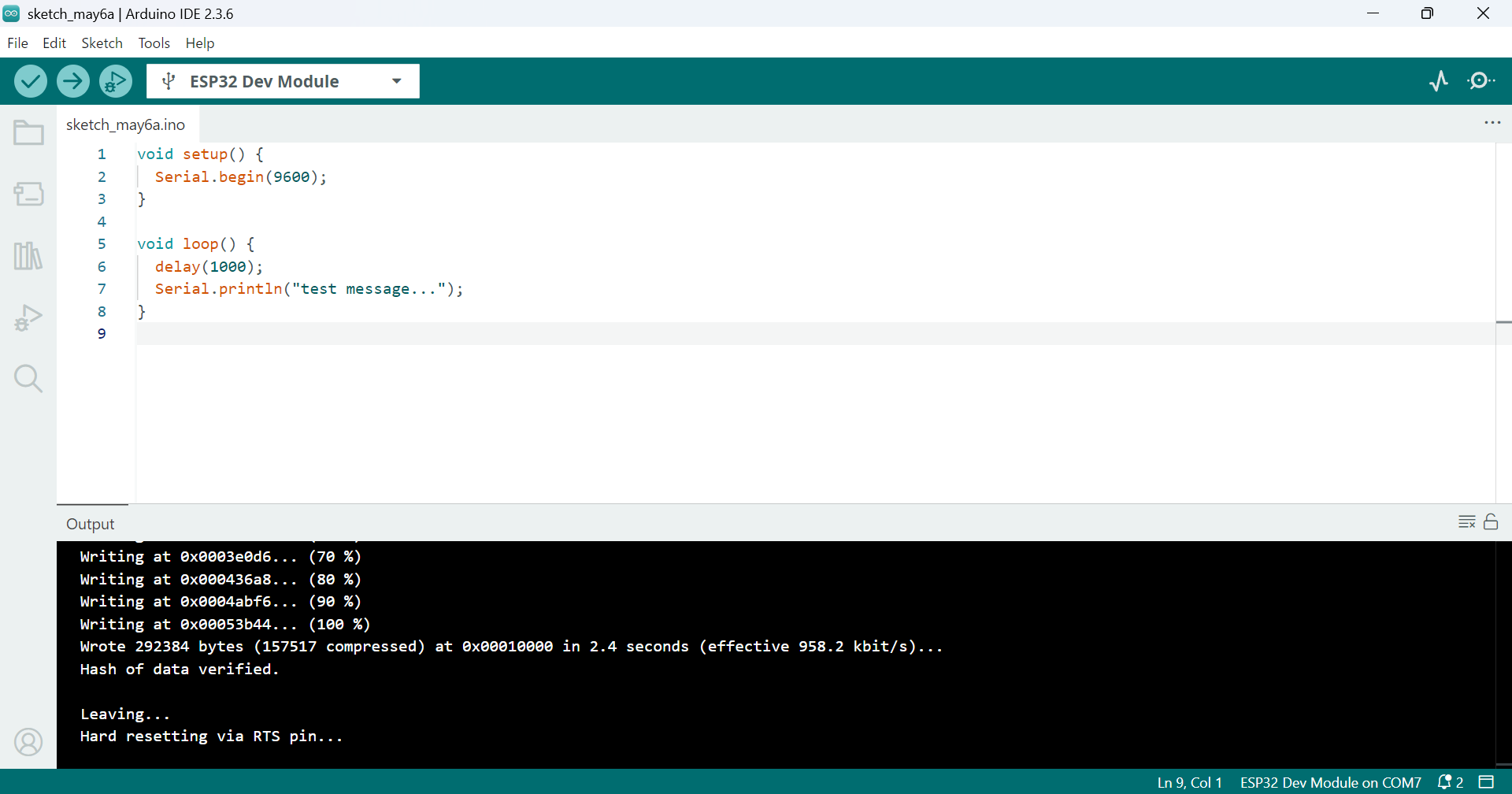
👆上記表示になったらアップロード完了です。

👆"Tools"-"Serial Monitor"を選択します。
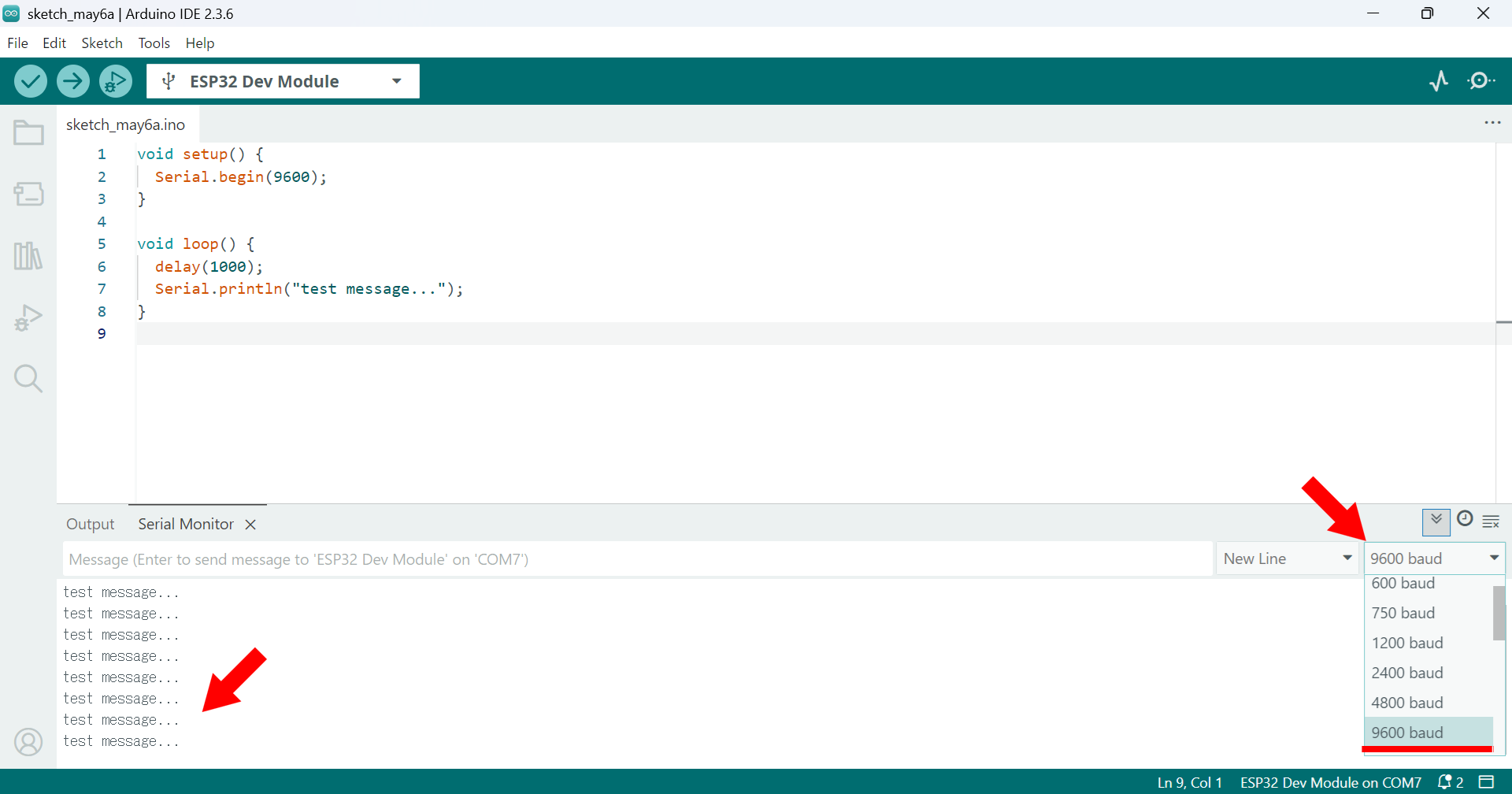
👆右下の通信速度は9600を選択します。
すると、下部にメッセージ"test message..."が1秒間隔で出力されます。
MicroPython でプログラム書き込み
Aruduino IDEのC言語ベースの言語はどうも苦手だという方のために、(私はそういう人ですが・・)MicroPython でプログラム書き込みする方法を解説します。
esptoolのインストール
Pythonがインストールされていることを前提に、下記コマンドでesptoolをインストールします。
pip install esptool
上記コマンドでインストールは完了しており、esptoolが使える状態になるのですが、私の場合パスが通っておらず、esptoolの実行ができなかったので、追加手順を解説します。
下記コマンドで、esptoolのインストールパスを確認します。
pip show esptool
以下の出力が得られます。
Name: esptool
Version: 4.8.1
Summary: A serial utility to communicate & flash code to Espressif chips.
Home-page:
Author: Fredrik Ahlberg (themadinventor), Angus Gratton (projectgus), Espressif Systems
Author-email:
License: GPLv2+
Location: C:\Users\sampleuser01\AppData\Local\Packages\PythonSoftwareFoundation.Python.3.11_qbz5n2kfra8p0\LocalCache\local-packages\Python311\site-packages
Requires: bitstring, cryptography, ecdsa, intelhex, pyserial, PyYAML, reedsolo
Required-by:
Locationの出力を手がかりに周辺フォルダを探すと、下記パスにesptoolが配置されていることを確認できました。
C:\Users\sampleuser01\AppData\Local\Packages\PythonSoftwareFoundation.Python.3.11_qbz5n2kfra8p0\LocalCache\local-packages\Python311\Scripts\esptool.exe
そこで、下記パスをPATH環境変数に追加することでesptoolが使えるようになりました。
C:\Users\sampleuser01\AppData\Local\Packages\PythonSoftwareFoundation.Python.3.11_qbz5n2kfra8p0\LocalCache\local-packages\Python311\Scripts\

ファームウェアのインストール
ESP32 / WROOMを参考にESP32-WROVER-E開発ボード用のMicroPythonファームウェアをインストールします。
下記コマンドでフラッシュをクリアします。
※ ポートは利用環境に合わせて変更して下さい。
esptool --port COM7 erase_flash
ESP32 / WROOMから最新バージョンのファームウェアをダウンロードします。
※ 本記事執筆時点ではESP32_GENERIC-20250415-v1.25.0.binでした。
ファームウェアをダウンロードしたフォルダへ移動し、下記コマンドでインストールします。
※ ポート及びファームウェアバージョンは利用環境に合わせて変更して下さい。
esptool --port COM7 --baud 460800 write_flash 0x1000 ESP32_GENERIC-20250415-v1.25.0.bin
出力内容を参考に記載します。
>esptool --port COM7 --baud 460800 write_flash 0x1000 ESP32_GENERIC-20250415-v1.25.0.bin
esptool.py v4.8.1
Serial port COM7
Connecting........................
Detecting chip type... Unsupported detection protocol, switching and trying again...
Connecting................
Detecting chip type... ESP32
Chip is ESP32-D0WD-V3 (revision v3.1)
Features: WiFi, BT, Dual Core, 240MHz, VRef calibration in efuse, Coding Scheme None
Crystal is 40MHz
MAC: d0:ef:76:79:22:1c
Uploading stub...
Running stub...
Stub running...
Changing baud rate to 460800
Changed.
Configuring flash size...
Flash will be erased from 0x00001000 to 0x001a0fff...
Compressed 1702240 bytes to 1117021...
Wrote 1702240 bytes (1117021 compressed) at 0x00001000 in 27.4 seconds (effective 497.0 kbit/s)...
Hash of data verified.

Leaving...
Hard resetting via RTS pin...
Thonnyのインストールと設定
Thonnyのページからインストーラをダウンロードしてインストールします。

👆Thonnyを起動し、Tools-Optionsを選択します。

👆InterpreterタブのinerpriterにMicropython(ESP32)、PortにUSBシリアル変換モジュールのポートを指定します。

👆こんな感じの表示になります。
中央の領域に以下のサンプルコードを入力し、保存ボタンをクリックします。
import time
while True:
    time.sleep(1)
    print("test message")

👆MicroPython Device を選択します。

👆File Name にmain.pyと入力し、OKをクリックします。
main.pyはESP32の起動時に自動実行されるファイル名です。

👆ESP32が再起動し、1秒間隔でtest messageとコンソールに出力されます。
これでMycroPythonでのプログラム書き込みの確認ができたことになります。
用品一覧
上記の解説で使う用品とリンクです。

👆ESP32-DevKitC-VE ESP32-WROVER-E開発ボード 8MB
👇関連記事
- 1 . XBeeを使った自宅状態遠隔見守りサービス実現方法の紹介
- 2 . XBee受信側の接続と設定
- 3 . XBee送信側の接続と設定
- 4 . XBee接続確認とセンサーの接続
- 5 . ESP32マイコンのツール設定と接続
- ESP32-C3-WROOM-02-N4 設定方法解説
👇参考URL
本記事へのリンク

https://docs.saurus12.com/device/esp32_preparation
[keywords]
ESP32 ESP32-DevKitC-VE ESP32-WROVER-E開発ボード Arduino IDE
5 . ESP32-WROVER-E開発ボードのツール設定と接続
更新日:2025年05月25日