DEMOサイト はこちら
https://forestacdev.github.io/maplibre-terrain-visualizer/
ソースコードはこちら
はじめに
MapLibre GL JS にはタイルの描画処理に別の処理を挟むことができるaddProtocol関数が存在します。
この記事ではこのaddProtocol関数の処理にWebGLの画像処理を加えることでクライアントサイドで動的にラスタータイルを加工して描画する方法を紹介します。
今回は、林野庁が昨年公開した森林資源情報データの一部で、G空間情報センターから提供されている栃木県 数値標高モデル(DEM)0.5mのラスタータイル(標高タイル)を使用します。
addProtocol関数の準備
addProtocol関数を発火させるにはsourceプロパティのtilesのURLの先頭に<protocol_name>://と記述し、そのsourceを使用したlayerが地図に追加されていると、タイルリクエストのたびに発火されます(今回はwebglとしている)。
またaddProtocolで返されるリクエストURLはそのままだと、XYZのタイル座標の取得に正規表現を使用してタイル座標を取り出すことになりますが、今回はURLパラメーターを持たせることでタイル座標を取り出しやすくします。
npm i maplibre-gl
import maplibregl from 'maplibre-gl';
import 'maplibre-gl/dist/maplibre-gl.css';

// 地図の表示
const map = new maplibregl.Map({
    container: 'map',
    style: {
        version: 8,
        glyphs: 'https://demotiles.maplibre.org/font/{fontstack}/{range}.pbf',
        sources: {
            // addProtocolでカスタム処理を加えるsource
            webgl: {
                type: 'raster',
                tiles: [`webgl://https://rinya-tochigi.geospatial.jp/2023/rinya/tile/terrainRGB/{z}/{x}/{y}.png?x={x}&y={y}&z={z}`], // タイル座標の部分をURLパラメーターに持たせる
                tileSize: 256,
                minzoom: 2,
                maxzoom: 18,
                attribution: '栃木県',
                bounds: [139.326731, 36.199924, 140.291983, 37.155039],
            },
        },
        layers: [
            {
                id: 'webgl_layer',
                source: 'webgl',
                type: 'raster',
                maxzoom: 24,
            },
        ],
    },
    center: [139.50785, 36.7751],
    zoom: 13.5,
    renderWorldCopies: false, // 地図をループさせない
});
上記のコードでカスタムプロトコルを書き込んでますが、そのままのタイルURLを読むと以下のような表示になります。表示してる場所は「男体山」の付近です。
このTerrain-RGB形式のタイル画像をカスタマイズしていきます。
Webワーカーの活用
公式ドキュメントの説明にも書いてある通り、addProtocol関数はメインスレッド上で呼び出されるため、画像処理のような重い負荷がかかると地図の描画速度が低下する可能性があります。そのため、今回はWebワーカーを活用してメインスレッドの負担を軽減します。
Webワーカーを使うことで、重い計算処理をバックグラウンドで実行し、非同期に処理を行うことができます。
例(vite環境での実装)
// ワーカーを作成
const worker = new Worker(new URL('./worker.ts', import.meta.url), { type: 'module' });

// メインスレッドからメッセージを送信
worker.postMessage('データ');

// ワーカーからのメッセージを受け取る
worker.onmessage = (event: MessageEvent<string>) => {
    console.log('メッセージを受信しました:', event.data);
};
// 受け取ったメッセージを処理し、結果を返す
onmessage = (event: MessageEvent<string>) => {

    // ここで何らかの重い処理を行う
    const result = ...


    postMessage(result);
};
今回は、複数のワーカースレッドを使用して並行処理を効率化するためのワーカープール (WorkerProtocolPool クラス) を実装し、さらに画像加工の重い処理をワーカースレッドにオフロードするためのWorkerProtocol クラスを用意します。addProtocol関数のなかでタイルリクエストのURLを受け取り、WorkerProtocolPoolにURLを渡します。
const workerProtocolPool = new WorkerProtocolPool(4); // 4つのワーカースレッドを持つプールを作成

maplibregl.addProtocol('webgl', (params, abortController) => {
    const urlWithoutProtocol = params.url.replace(`webgl://`, '');
    const url = new URL(urlWithoutProtocol);
    return workerProtocolPool.request(url, abortController);
});
WorkerProtocolPoolクラスを記述します。このクラスは、受け取ったタイルURLを各WorkerProtocolに渡して処理します。本来は使用するマシンのコア数を基にスレッド数を決定するのが理想ですが、今回は4つのスレッドを使用するように指定してます。requestメソッドにより、タイルリクエストをワーカースレッドで非同期に処理し、メインスレッドの負担を軽減します。
class WorkerProtocolPool {
    private workers: WorkerProtocol[] = [];
    private workerIndex = 0;
    private poolSize: number;

    constructor(poolSize: number) {
        this.poolSize = poolSize;

        // 指定されたプールサイズのワーカープロトコルを作成
        for (let i = 0; i < poolSize; i++) {
            const worker = new Worker(new URL('./worker.ts', import.meta.url), { type: 'module' });
            this.workers.push(new WorkerProtocol(worker));
        }
    }

    // ラウンドロビン方式で次のワーカーを取得
    private getNextWorker(): WorkerProtocol {
        const worker = this.workers[this.workerIndex];
        this.workerIndex = (this.workerIndex + 1) % this.poolSize;
        return worker;
    }

    // タイルリクエストを処理する
    async request(url: URL, controller: AbortController): Promise<{ data: Uint8Array }> {
        const worker = this.getNextWorker();
        return worker.request(url, controller);
    }
}
メインスレッドからワーカーにリクエストを送る部分であるWorkerProtocolクラスを記述します。ここでタイル画像の加工処理に必要なパラメーターを用意するのですが、まず全体のコードはこちらになります。
class WorkerProtocol {
    private worker: Worker;
    private pendingRequests: Map<
        string,
        {
            resolve: (value: { data: Uint8Array } | PromiseLike<{ data: Uint8Array }>) => void;
            reject: (reason?: Error) => void;
            controller: AbortController;
        }
    >;
    private tileCache: TileImageManager;
    private colorMapCache: ColorMapManager;

    constructor(worker: Worker) {
        this.worker = worker;
        this.pendingRequests = new Map();
        this.tileCache = TileImageManager.getInstance();
        this.colorMapCache = new ColorMapManager();
        this.worker.addEventListener('message', this.handleMessage);
        this.worker.addEventListener('error', this.handleError);
    }

    async request(url: URL, controller: AbortController): Promise<{ data: Uint8Array }> {
        const x = parseInt(url.searchParams.get('x') || '0', 10);
        const y = parseInt(url.searchParams.get('y') || '0', 10);
        const z = parseInt(url.searchParams.get('z') || '0', 10);
        const baseUrl = 'https://rinya-tochigi.geospatial.jp/2023/rinya/tile/terrainRGB/{z}/{x}/{y}.png';

        const images = await this.tileCache.getAdjacentTilesWithImages(x, y, z, baseUrl, controller);

        return new Promise((resolve, reject) => {
            const center = images.center;
            const tileId = center.tileId;
            const left = images.left;
            const right = images.right;
            const top = images.top;
            const bottom = images.bottom;
            this.pendingRequests.set(tileId, { resolve, reject, controller });

            const elevationColorArray = this.colorMapCache.createColorArray('cool');

            this.worker.postMessage({
                tileId,
                center: center.image,
                left: left.image,
                right: right.image,
                top: top.image,
                bottom: bottom.image,
                z,
                uniformsData: uniformsData,
                elevationColorArray,
            });
        });
    }

    private handleMessage = (e: MessageEvent) => {
        const { id, buffer, error } = e.data;
        const request = this.pendingRequests.get(id);
        if (error) {
            console.error(`Error processing tile ${id}:`, error);
            if (request) {
                request.reject(new Error(error));
                this.pendingRequests.delete(id);
            }
        } else if (request) {
            request.resolve({ data: buffer });
            this.pendingRequests.delete(id);
        }
    };

    private handleError(e: ErrorEvent) {
        console.error('Worker error:', e);
        this.pendingRequests.forEach((request) => {
            request.reject(new Error('Worker error occurred'));
        });
        this.pendingRequests.clear();
    }
}
requestメソッドの部分がタイル画像の読み込みとパラメーターの送信を行なってます。
handleMessageメソッドはワーカースレッドから処理が完了したタイル画像を受け取った後、addProtocolの返り値として{ data: buffer }を返しています。この処理において、各タイル画像にid(タイルID)を持たせている理由は、非同期処理のために受け取るタイル画像の順番がばらつくことがあるためです。これによって、返されたタイル画像が正しいタイル座標に一致しないケースが発生する可能性があります。idを持たせることで、正しいタイル画像が適切な位置に描画されるようにし、描画位置のずれを防いでいます。
handleErrorメソッドは、ワーカースレッドでエラーが発生した場合に呼び出されます。
では、メインの処理になるrequest部分についての解説になります。addProtocol関数からタイルURLとAbortControllerを受け取っています。このAbortControllerはタイルリクエストのキャンセル処理に必要なものです(レスポンス待ちの状態で地図がそのタイル座標外に移動した場合に発生する)。
URLからパラメーターとして持たせていたタイル座標(x、y、z)を取得し、もとのラスタータイルのURLと一緒にTileImageManagerクラスのgetAdjacentTilesWithImagesというメソッドに渡してます。
// WorkerProtocolクラスのrequestメソッド
async request(url: URL, controller: AbortController): Promise<{ data: Uint8Array }> {
        // タイル座標からIDとURLを生成
        const x = parseInt(url.searchParams.get('x') || '0', 10);
        const y = parseInt(url.searchParams.get('y') || '0', 10);
        const z = parseInt(url.searchParams.get('z') || '0', 10);
        const baseUrl = 'https://rinya-tochigi.geospatial.jp/2023/rinya/tile/terrainRGB/{z}/{x}/{y}.png';

        // 画像の取得
        const images = await this.tileCache.getAdjacentTilesWithImages(x, y, z, baseUrl, controller);

        // 省略
    }
getAdjacentTilesWithImagesについては次の章で解説します。
タイル画像の読み込み
タイル画像関係の処理をTileImageManagerクラスに記述します。
type TileImageData = { [position: string]: { tileId: string; image: ImageBitmap } };

// タイル画像の処理
export class TileImageManager {
    private static instance: TileImageManager;
    private cache: Map<string, ImageBitmap>;
    private cacheSizeLimit: number;
    private cacheOrder: string[];

    private constructor(cacheSizeLimit = 500) {
        this.cache = new Map();
        this.cacheSizeLimit = cacheSizeLimit;
        this.cacheOrder = [];
    }

    // TileImageManager のインスタンスを取得する静的メソッド
    public static getInstance(cacheSizeLimit = 500): TileImageManager {
        if (!TileImageManager.instance) {
            TileImageManager.instance = new TileImageManager(cacheSizeLimit);
        }
        return TileImageManager.instance;
    }

    public async loadImage(src: string, signal: AbortSignal): Promise<ImageBitmap> {
        try {
            const response = await fetch(src, { signal });
            if (!response.ok) {
                throw new Error('Failed to fetch image');
            }
            return await createImageBitmap(await response.blob());
        } catch (error) {
            if (error instanceof Error && error.name === 'AbortError') {
                // リクエストがキャンセルされた場合はエラーをスロー
                throw error;
            } else {
                // 他のエラー時には空の画像を返す
                return await createImageBitmap(new ImageData(1, 1));
            }
        }
    }

    public async getAdjacentTilesWithImages(x: number, y: number, z: number, baseurl: string, controller: AbortController): Promise<TileImageData> {
        const positions = [
            { position: 'center', dx: 0, dy: 0 },
            { position: 'left', dx: -1, dy: 0 },
            { position: 'right', dx: 1, dy: 0 },
            { position: 'top', dx: 0, dy: -1 },
            { position: 'bottom', dx: 0, dy: 1 },
        ];

        const result: TileImageData = {};

        await Promise.all(
            positions.map(async ({ position, dx, dy }) => {
                const tileX = x + dx;
                const tileY = y + dy;
                const imageUrl = baseurl.replace('{x}', tileX.toString()).replace('{y}', tileY.toString()).replace('{z}', z.toString());

                // キャッシュにタイル画像があればそれを使う。なければ新たにリクエストを送る
                const imageBitmap = this.cache.has(imageUrl) ? this.cache.get(imageUrl) : await this.loadImage(imageUrl, controller.signal);
                if (!imageBitmap) return;
                this.add(imageUrl, imageBitmap);

                result[position] = { tileId: imageUrl, image: imageBitmap };
            }),
        );

        return result;
    }

    add(tileId: string, image: ImageBitmap): void {
        if (this.cacheOrder.length >= this.cacheSizeLimit) {
            const oldestTileId = this.cacheOrder.shift();
            if (oldestTileId) {
                this.cache.delete(oldestTileId);
            }
        }

        this.cache.set(tileId, image);

        const index = this.cacheOrder.indexOf(tileId);
        if (index > -1) {
            this.cacheOrder.splice(index, 1);
        }
        this.cacheOrder.push(tileId);
    }

    get(tileId: string): ImageBitmap | undefined {
        return this.cache.get(tileId);
    }

    has(tileId: string): boolean {
        return this.cache.has(tileId);
    }

    clear(): void {
        this.cache.clear();
        this.cacheOrder = [];
    }
}
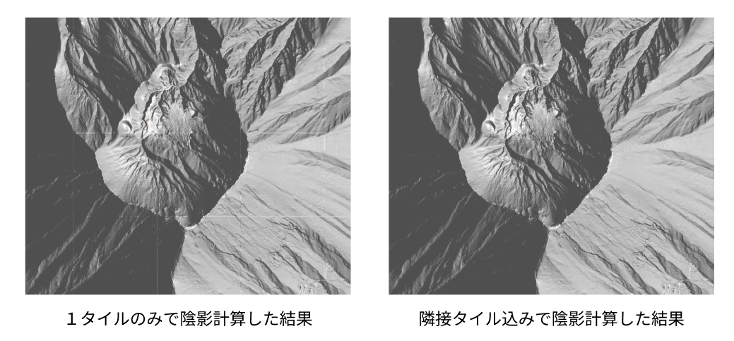
このクラスのgetAdjacentTilesWithImagesメソッドでタイル画像を読み込む処理をしています。今回は標高値から陰影などを描画するときに必要な法線ベクトルを計算する時に、一枚のタイル画像だと端っこのピクセルの法線が正しく計算できないため、1つのタイルリクエストにたいして隣接するタイルも読み込むように、上下左右のタイル座標も計算しています。
仮に1つのタイルで法線ベクトルを計算する場合、端っこにピクセルがない場合は自身のピクセルが隣にあると仮定して計算することである程度は誤魔化せますが、ズームレベルが高いタイルになていくとタイルの境界が見えるようになり不自然になります。

この方法だとそれぞれのタイルリクエストで読み込むタイル画像の座標がかぶり、2回目以降の読み込みが発生するタイル画像が頻繁に出てくるため、一度読み込んだタイル画像は内部でキャッシュを持たせ再利用できるようにします。そして古くなったキャッシュは削除するようにします。
また、今回は地形のタイルを読み込んでおり、キャッシュに残っているタイルは terrain の3D地形表示のタイルとして再利用できるため、このクラスではシングルトンパターンを採用しています。
再びWorkerProtocolに戻りgetAdjacentTilesWithImages関数で返されたデータをワーカースレッドに送信している部分の解説です。
// WorkerProtocolクラスのrequestメソッド
async request(url: URL, controller: AbortController): Promise<{ data: Uint8Array }> {

        // 省略

        // 画像の取得
        const images = await this.tileCache.getAdjacentTilesWithImages(x, y, z, baseUrl, controller);

        return new Promise((resolve, reject) => {
            const center = images.center; // 中央のタイル
            const tileId = center.tileId; // ワーカー用ID
            const left = images.left; // 左のタイル
            const right = images.right; // 右のタイル
            const top = images.top; // 上のタイル
            const bottom = images.bottom; // 下のタイル
            this.pendingRequests.set(tileId, { resolve, reject, controller });

            const elevationColorArray = this.colorMapCache.createColorArray('cool');

            this.worker.postMessage({
                tileId,
                center: center.image,
                left: left.image,
                right: right.image,
                top: top.image,
                bottom: bottom.image,
                z,
                uniformsData: uniformsData,
                elevationColorArray,
            });
        });
    }
タイルリクエストのURLをワーカースレッドの並列処理から適切に結果を受け取るようにidとしてわたし、取得したタイル画像とその隣接する上下左右を含めた5枚の画像と、現在のズームレベル、標高段彩図の描画に必要なカラーマップ、そしてそのほかのパラメーターであるuniformsDataをワーカースレッドに送信してます
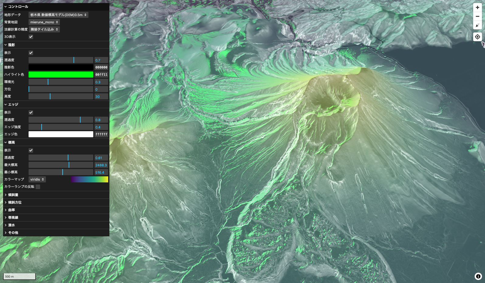
ユニフォーム変数でシェーダー側に渡したパラメーターはこちらです。今回は標高段彩図と陰影とエッジの描画に必要な各パラメーターを渡してます。
export type UniformsData = {
    elevation: {
        opacity: number;
        maxHeight: number;
        minHeight: number;
    };
    shadow: {
        opacity: number;
        shadowColor: string;
        highlightColor: string;
        ambient: number;
        azimuth: number;
        altitude: number;
    };
    edge: {
        opacity: number;
        edgeIntensity: number;
        edgeColor: string;
    };
};

// ユニフォーム変数
export const uniformsData: UniformsData = {
    // 標高
    elevation: {
        opacity: 1.0, // 不透明度
        maxHeight: 2500, // 最大標高値
        minHeight: 500, // 最小標高値
    },
    // 陰影
    shadow: {
        opacity: 0.8, // 不透明度
        shadowColor: '#000000', // 陰影色
        highlightColor: '#00ff9d', // ハイライト色
        ambient: 0.3, // 環境光
        azimuth: 0, // 方位
        altitude: 30, // 太陽高度
    },
    // エッジ
    edge: {
        opacity: 0.9, // 不透明度
        edgeIntensity: 0.4, // エッジ強度
        edgeColor: '#ffffff', // エッジカラー
    },
};
標高段彩図に必要なカラーマップはColorMapManagerクラスのcreateColorArray('cool')メソッドで取得してます。この部分は次の章で解説します。
カラーマップデータの作成
ColorMapManagerというクラスを用意します。このクラスは、カラーマップデータを生成し、シェーダーで使用できるようにキャッシュする役割を持っています。このカラーマップは、シェーダーに渡す際にテクスチャとして使用します。テクスチャを用いることで、配列データとして渡すよりも効率よく処理を行うことが可能です。また、こちらも一度作成したカラーマップは再利用できるようにキャッシュをもたせます。これによりタイルリクエストのたびにカラーマップを作成しなくても済みます。カラーマップの配列作成にはcolormapライブラリを使用しています。
npm i colormap
npm i --save-dev @types/colormap
import colormap from 'colormap';

// カラーマップデータを作成するクラス
export class ColorMapManager {
    private cache: Map<string, Uint8Array>;
    public constructor() {
        this.cache = new Map();
    }
    public createColorArray(colorMapName: string): Uint8Array {
        const cacheKey = `${colorMapName}`;

        if (this.has(cacheKey)) {
            return this.get(cacheKey) as Uint8Array;
        }

        const width = 256;
        const pixels = new Uint8Array(width * 3); // RGBのみの3チャンネルデータ

        // オプションオブジェクトを作成
        const options = {
            colormap: colorMapName,
            nshades: width,
            format: 'rgb', // RGBAからRGBに変更
            alpha: 1,
        };

        let colors = colormap(options as any);

        // RGBデータの格納
        let ptr = 0;
        for (let i = 0; i < width; i++) {
            const color = colors[i] as number[];
            pixels[ptr++] = color[0];
            pixels[ptr++] = color[1];
            pixels[ptr++] = color[2];
        }

        // キャッシュに格納して再利用可能にする
        this.cache.set(cacheKey, pixels);

        return pixels;
    }

    add(cacheKey: string, pixels: Uint8Array): void {
        this.cache.set(cacheKey, pixels);
    }

    get(cacheKey: string): Uint8Array | undefined {
        return this.cache.get(cacheKey);
    }

    has(cacheKey: string): boolean {
        return this.cache.has(cacheKey);
    }
}
WebGLの処理
ワーカースレッド内でWebGLの処理を書いていきます。
シェーダープログラムを作成するinitWebGLを記述します。この関数は最初の一回だけ呼び出される部分です。それ以降のタイルリクエスト時の呼び出しは不要です。
import fsSource from './shader/fragment.glsl?raw';
import vsSource from './shader/vertex.glsl?raw';

let gl: WebGL2RenderingContext | null = null;
let program: WebGLProgram | null = null;
let positionBuffer: WebGLBuffer | null = null;

const initWebGL = (canvas: OffscreenCanvas) => {
    gl = canvas.getContext('webgl2');
    if (!gl) {
        throw new Error('WebGL not supported');
    }

    const loadShader = (gl: WebGL2RenderingContext, type: number, source: string): WebGLShader | null => {
        const shader = gl.createShader(type);
        if (!shader) {
            console.error('Unable to create shader');
            return null;
        }
        gl.shaderSource(shader, source);
        gl.compileShader(shader);

        if (!gl.getShaderParameter(shader, gl.COMPILE_STATUS)) {
            console.error('An error occurred compiling the shaders: ' + gl.getShaderInfoLog(shader));
            gl.deleteShader(shader);
            return null;
        }
        return shader;
    };

    const vertexShader = loadShader(gl, gl.VERTEX_SHADER, vsSource);
    const fragmentShader = loadShader(gl, gl.FRAGMENT_SHADER, fsSource);
    if (!vertexShader || !fragmentShader) {
        throw new Error('Failed to load shaders');
    }

    program = gl.createProgram();
    if (!program) {
        throw new Error('Failed to create program');
    }
    gl.attachShader(program, vertexShader);
    gl.attachShader(program, fragmentShader);
    gl.linkProgram(program);

    if (!gl.getProgramParameter(program, gl.LINK_STATUS)) {
        console.error('Unable to initialize the shader program: ' + gl.getProgramInfoLog(program));
        throw new Error('Failed to link program');
    }

    gl.useProgram(program);

    positionBuffer = gl.createBuffer();
    gl.bindBuffer(gl.ARRAY_BUFFER, positionBuffer);
    const positions = new Float32Array([-1, -1, 1, -1, -1, 1, 1, 1]);
    gl.bufferData(gl.ARRAY_BUFFER, positions, gl.STATIC_DRAW);
    const positionLocation = gl.getAttribLocation(program, 'a_position');
    gl.enableVertexAttribArray(positionLocation);
    gl.vertexAttribPointer(positionLocation, 2, gl.FLOAT, false, 0, 0);
};
WebGLにユニフォーム変数を渡しやすいようにsetUniforms関数と複数のタイル画像をバインドするbindTextures関数を用意します。陰影計算に必要な光方向のベクトルを取得するcalculateLightDirection関数も用意します。
const bindTextures = (gl: WebGL2RenderingContext, program: WebGLProgram, textures: { [name: string]: { image: ImageBitmap | Uint8Array; type: 'height' | 'colormap' } }) => {
    let textureUnit = gl.TEXTURE0;

    Object.entries(textures).forEach(([uniformName, { image, type }]) => {
        // テクスチャをバインド
        const texture = gl.createTexture();
        gl.activeTexture(textureUnit); // 現在のテクスチャユニットをアクティブ
        gl.bindTexture(gl.TEXTURE_2D, texture);

        const location = gl.getUniformLocation(program, uniformName);
        gl.uniform1i(location, textureUnit - gl.TEXTURE0);

        if (type === 'height') {
            gl.texImage2D(gl.TEXTURE_2D, 0, gl.RGBA, gl.RGBA, gl.UNSIGNED_BYTE, image as ImageBitmap);
        } else {
            gl.texImage2D(gl.TEXTURE_2D, 0, gl.RGB, 256, 1, 0, gl.RGB, gl.UNSIGNED_BYTE, image as Uint8Array);
        }

        // ラッピングとフィルタリングの設定
        gl.texParameteri(gl.TEXTURE_2D, gl.TEXTURE_WRAP_S, gl.CLAMP_TO_EDGE);
        gl.texParameteri(gl.TEXTURE_2D, gl.TEXTURE_WRAP_T, gl.CLAMP_TO_EDGE);
        gl.texParameteri(gl.TEXTURE_2D, gl.TEXTURE_MIN_FILTER, gl.LINEAR);
        gl.texParameteri(gl.TEXTURE_2D, gl.TEXTURE_MAG_FILTER, gl.LINEAR);

        textureUnit += 1; // 次のテクスチャユニットへ
    });
};

type UniformValue = {
    type: '1f' | '1i' | '4fv' | '3fv'; // 型指定
    value: number | Float32Array | Int32Array | number[];
};

type Uniforms = {
    [name: string]: UniformValue;
};

const setUniforms = (gl: WebGL2RenderingContext, program: WebGLProgram, uniforms: Uniforms): void => {
    for (const [name, { type, value }] of Object.entries(uniforms)) {
        const location = gl.getUniformLocation(program, name);
        if (location !== null) {
            (gl as any)[`uniform${type}`](location, value);
        }
    }
};

const calculateLightDirection = (azimuth: number, altitude: number) => {
    // 方位角と高度をラジアンに変換
    const azimuthRad = (azimuth * Math.PI) / 180;
    const altitudeRad = (altitude * Math.PI) / 180;

    // 光の方向ベクトルを計算
    const x = Math.cos(altitudeRad) * Math.sin(azimuthRad);
    const y = Math.sin(altitudeRad);
    const z = -Math.cos(altitudeRad) * Math.cos(azimuthRad); // 北がZ軸の負の方向

    return [x, y, z];
};
メインスレッドから受け取ったデータを処理するonmessageの部分を記述します。各パラメーターをシェーダーに設定し、描画結果をarrayBufferに変換して、postMessageでidと共にメインスレッドに返します。
各色の情報は10進数のカラーとなっているため、chroma.jsのglメソッドを使ってシェーダーで使用できる0から1の範囲の値に変換します。
npm i chroma-js
npm i --save-dev @types/chroma-js
import chroma from 'chroma-js';
import type { UniformsData } from './main';

const canvas = new OffscreenCanvas(256, 256);

self.onmessage = async (e) => {
    const { center, left, right, top, bottom, tileId, z, uniformsData, elevationColorArray } = e.data;
    try {
        if (!gl) {
            initWebGL(canvas);
        }

        if (!gl || !program || !positionBuffer) {
            throw new Error('WebGL initialization failed');
        }

        const { elevation, shadow, edge } = uniformsData as UniformsData;

        const lightDirection = calculateLightDirection(shadow.azimuth, shadow.altitude);

        const uniforms: Uniforms = {
            u_zoom_level: { type: '1f', value: z },
            u_elevation_alpha: { type: '1f', value: elevation.opacity },
            u_max_height: { type: '1f', value: elevation.maxHeight },
            u_min_height: { type: '1f', value: elevation.minHeight },
            u_shadow_strength: { type: '1f', value: shadow.opacity },
            u_light_direction: { type: '3fv', value: lightDirection },
            u_shadow_color: { type: '4fv', value: chroma(shadow.shadowColor).gl() },
            u_highlight_color: { type: '4fv', value: chroma(shadow.highlightColor).gl() },
            u_ambient: { type: '1f', value: shadow.ambient },
            u_edge_alpha: { type: '1f', value: edge.opacity },
            u_edge_color: { type: '4fv', value: chroma(edge.edgeColor).gl() },
            u_edge_intensity: { type: '1f', value: edge.edgeIntensity },
        };

        setUniforms(gl, program, uniforms);

        // テクスチャ
        bindTextures(gl, program, {
            u_height_map_center: { image: center, type: 'height' },
            u_height_map_left: { image: left, type: 'height' },
            u_height_map_right: { image: right, type: 'height' },
            u_height_map_top: { image: top, type: 'height' },
            u_height_map_bottom: { image: bottom, type: 'height' },
            u_elevationMap: { image: elevationColorArray, type: 'colormap' },
        });

        gl.clear(gl.COLOR_BUFFER_BIT);
        gl.drawArrays(gl.TRIANGLE_STRIP, 0, 4);

        const blob = await canvas.convertToBlob();
        if (!blob) {
            throw new Error('Failed to convert canvas to blob');
        }

        const buffer = await blob.arrayBuffer();
        self.postMessage({ id: tileId, buffer });
    } catch (error) {
        if (error instanceof Error) {
            self.postMessage({ id: tileId, error: error.message });
        }
    }
};
シェーダーでタイル画像を加工する
ここまで長くなりましたが、タイル画像処理の要となるシェーダー部分の解説です。
頂点シェーダーではUV座標を使用しているため、タイル画像が上下反転してしまいます。このため、Y軸を反転させる必要があります。
#version 300 es
in vec4 a_position;
out vec2 v_tex_coord;

void main() {
    gl_Position = a_position;
    v_tex_coord = vec2(a_position.x * 0.5 + 0.5, a_position.y * -0.5 + 0.5); // Y軸を反転
}
次にフラグメントシェーダーでタイル画像を加工します。ちなみにprecision highp floatの記述がないと、スマホではシェーダーで加工したタイル画像がうまく描画されないみたいです。
#version 300 es
precision highp float;

uniform sampler2D u_height_map_center;
uniform sampler2D u_height_map_left;
uniform sampler2D u_height_map_right;
uniform sampler2D u_height_map_top;
uniform sampler2D u_height_map_bottom;

in vec2 v_tex_coord ;
out vec4 fragColor;
タイル座標から標高値を計算する関数を記述します。今回はTerrain-RPGでのデコード計算をします。
// 高さ変換関数
// mapbox (TerrainRGB)
float convertToHeight(vec4 color) {
    vec3 rgb = color.rgb * 255.0;
    return -10000.0 + dot(rgb, vec3(256.0 * 256.0, 256.0, 1.0)) * 0.1;
}
ちなみに他の形式である地理院標高タイルやTerrarium-RGBの場合は以下のように計算します。
// gsi (地理院標高タイル)
float convertToHeight(vec4 color) {
    vec3 rgb = color.rgb * 255.0;
    float total = dot(rgb, vec3(65536.0, 256.0, 1.0));
    return mix(total, total - 16777216.0, step(8388608.0, total)) * 0.01;
}

// terrarium (TerrariumRGB)
float convertToHeight(vec4 color) {
    vec3 rgb = color.rgb * 255.0;
    return (rgb.r * 256.0 + rgb.g + rgb.b / 256.0) - 32768.0;
}
陰影を描画するには法線の計算が必要になります。標高データの高さマトリックスと法線情報を格納するTerrainDataを作成します。中央のタイル画像の角ピクセルの隣接するピクセルの標高値をもとに法線ベクトルを計算します。端っこのピクセルの場合は隣のタイル画像のピクセルを法線計算の対象にします。
struct TerrainData {
    vec3 normal;
    mat3 h_mat;
};

TerrainData calculateTerrainData(vec2 uv) {

    TerrainData data;
    // 9マスピクセルのインデックス番号
    // ----------------------------
    // | [0][0] | [0][1] | [0][2] |
    // ----------------------------
    // | [1][0] | [1][1] | [1][2] |
    // ----------------------------
    // | [2][0] | [2][1] | [2][2] |
    // ----------------------------

    // height_mapの隣接タイル
    // ----------------------------
    // |        | top    |      |
    // ----------------------------
    // | left   | center | right  |
    // ----------------------------
    // |        | bottom |        |
    // ----------------------------

    vec2 pixel_size = vec2(1.0) / 256.0;


    // 端の場合は隣接テクスチャからサンプル
    // 左上
    data.h_mat[0][0] = convertToHeight(
        (uv.x <= pixel_size.x && uv.y <= pixel_size.y) ? texture(u_height_map_left, uv + vec2(1.0 - pixel_size.x, 1.0 - pixel_size.y)) :
        (uv.y <= pixel_size.y) ? texture(u_height_map_top, uv + vec2(-pixel_size.x, 1.0 - pixel_size.y)) :
        (uv.x <= pixel_size.x) ? texture(u_height_map_left, uv + vec2(1.0 - pixel_size.x, -pixel_size.y)) :
        texture(u_height_map_center, uv + vec2(-pixel_size.x, -pixel_size.y))
    );

    // 上
    data.h_mat[0][1] = convertToHeight(
        (uv.y <= pixel_size.y) ? texture(u_height_map_top, uv + vec2(0.0, 1.0 - pixel_size.y)) :
        texture(u_height_map_center, uv + vec2(0.0, -pixel_size.y))
    );

    // 右上
    data.h_mat[0][2] = convertToHeight(
        (uv.x >= 1.0 - pixel_size.x && uv.y <= pixel_size.y) ? texture(u_height_map_right, uv + vec2(-1.0 + pixel_size.x, 1.0 - pixel_size.y)) :
        (uv.y <= pixel_size.y) ? texture(u_height_map_top, uv + vec2(pixel_size.x, 1.0 - pixel_size.y)) :
        (uv.x >= 1.0 - pixel_size.x) ? texture(u_height_map_right, uv + vec2(-1.0 + pixel_size.x, -pixel_size.y)) :
        texture(u_height_map_center, uv + vec2(pixel_size.x, -pixel_size.y))
    );

    // 左
    data.h_mat[1][0] = convertToHeight(
        (uv.x <= pixel_size.x) ? texture(u_height_map_left, uv + vec2(1.0 - pixel_size.x, 0.0)) :
        texture(u_height_map_center, uv + vec2(-pixel_size.x, 0.0))
    );

    // 中央
    data.h_mat[1][1] = convertToHeight(texture(u_height_map_center, uv));

    // 右
    data.h_mat[1][2] = convertToHeight(
        (uv.x >= 1.0 - pixel_size.x) ? texture(u_height_map_right, uv + vec2(-1.0 + pixel_size.x, 0.0)) :
        texture(u_height_map_center, uv + vec2(pixel_size.x, 0.0))
    );

    // 左下
    data.h_mat[2][0] = convertToHeight(
        (uv.x <= pixel_size.x && uv.y >= 1.0 - pixel_size.y) ? texture(u_height_map_left, uv + vec2(1.0 - pixel_size.x, -1.0 + pixel_size.y)) :
        (uv.y >= 1.0 - pixel_size.y) ? texture(u_height_map_bottom, uv + vec2(-pixel_size.x, -1.0 + pixel_size.y)) :
        (uv.x <= pixel_size.x) ? texture(u_height_map_left, uv + vec2(1.0 - pixel_size.x, pixel_size.y)) :
        texture(u_height_map_center, uv + vec2(-pixel_size.x, pixel_size.y))
    );

    // 下
    data.h_mat[2][1] = convertToHeight(
        (uv.y >= 1.0 - pixel_size.y) ? texture(u_height_map_bottom, uv + vec2(0.0, -1.0 + pixel_size.y)) :
        texture(u_height_map_center, uv + vec2(0.0, pixel_size.y))
    );

    // 右下
    data.h_mat[2][2] = convertToHeight(
        (uv.x >= 1.0 - pixel_size.x && uv.y >= 1.0 - pixel_size.y) ? texture(u_height_map_right, uv + vec2(-1.0 + pixel_size.x, -1.0 + pixel_size.y)) :
        (uv.y >= 1.0 - pixel_size.y) ? texture(u_height_map_bottom, uv + vec2(pixel_size.x, -1.0 + pixel_size.y)) :
        (uv.x >= 1.0 - pixel_size.x) ? texture(u_height_map_right, uv + vec2(-1.0 + pixel_size.x, pixel_size.y)) :
        texture(u_height_map_center, uv + vec2(pixel_size.x, pixel_size.y))
    );

    // 法線の計算
    data.normal.x = (data.h_mat[0][0] + data.h_mat[0][1] + data.h_mat[0][2]) -
                    (data.h_mat[2][0] + data.h_mat[2][1] + data.h_mat[2][2]);
    data.normal.y = (data.h_mat[0][0] + data.h_mat[1][0] + data.h_mat[2][0]) -
                    (data.h_mat[0][2] + data.h_mat[1][2] + data.h_mat[2][2]);
    data.normal.z = 2.0 * pixel_size.x * 256.0; // スケーリング係数
    data.normal = normalize(data.normal);

    return data;
}
法線マップを作成し、確認で地図に出力してみます。
void main() {
    vec2 uv = v_tex_coord;
    vec4 final_color = vec4(0.0, 0.0,0.0,0.0);

    TerrainData terrain_data;
    terrain_data = calculateTerrainData(uv);

    vec3 normal = terrain_data.normal;

    vec3 normalizedColor = (normal + 1.0) * 0.5;
    final_color = vec4(normalizedColor, 1.0);

    fragColor = final_color;
}
こんな感じのカラフルな地形が描画されます。この色が法線の向きを示してます。
法線マップの計算がうまくいってるのを確認したら、シェーダーをさらに書いていきます。
標高段彩図の描画
シェーダー側に渡したカラーマップ(cool)はこちらです。
標高値からグラデーションを作成し標高段彩図を作ります。カラーマップのテクスチャ画像を色スケールの代わりとして計算します。
uniform sampler2D u_elevationMap;
uniform float u_min_height;
uniform float u_max_height;
uniform float u_elevation_alpha;

// 省略

// カラーマップテクスチャから色を取得する関数
vec4 getColorFromMap(sampler2D map, float value) {
    return vec4(texture(map, vec2(value, 0.5)).rgb, 1.0);
}

void main() {

    // 省略
    vec4 color = texture(u_height_map_center, uv);
    float h = convertToHeight(color);
    float normalized_h = clamp((h - u_min_height) / (u_max_height - u_min_height), 0.0, 1.0);
    vec4 terrain_color = getColorFromMap(u_elevationMap, normalized_h);
    final_color = mix(final_color, terrain_color, u_elevation_alpha);

    fragColor = final_color;
}
標高段彩図ができました。つぎはこれに陰影を重ねます。
陰影を重ねる
影を計算して描画します。ハイライトも加えます。
uniform float u_shadow_strength;
uniform float u_ambient;
uniform vec3 u_light_direction;
uniform vec4 u_shadow_color;
uniform vec4 u_highlight_color;

// 省略

void main() {

    // 省略

    // 陰影効果
    vec3 view_direction = normalize(vec3(0.0, 0.0, 1.0)); // 視線ベクトル
    float highlight_strength = 0.5; // ハイライトの強度

    // 拡散光の計算
    float diffuse = max(dot(normal, u_light_direction), 0.0);

    // 環境光と拡散光の合成
    float shadow_factor = u_ambient + (1.0 - u_ambient) * diffuse;
    float shadow_alpha = (1.0 - shadow_factor) * u_shadow_strength;

    // ハイライトの計算
    vec3 reflect_dir = reflect(-u_light_direction, normal); // 反射ベクトル
    float spec = pow(max(dot(view_direction, reflect_dir), 0.0), 16.0); // スペキュラ成分(光沢の鋭さ)
    vec3 final_highlight = highlight_strength * spec * u_highlight_color.rgb; // ハイライトの最終的な強度と色

    // ハイライトと影を重ねる
    final_color.rgb = mix(final_color.rgb, u_shadow_color.rgb, shadow_alpha); // 影の適用
    final_color.rgb += final_highlight; // ハイライトの適用
    final_color.a = final_color.a * (1.0 - shadow_alpha) + shadow_alpha;

    fragColor = final_color;
}
陰影がついたことで立体感が出てます。最後にエッジを重ねてみます。

エッジを重ねる
白いエッジを重ねて氷山みたいな感じにします。
uniform float u_zoom_level;
uniform float u_edge_alpha;
uniform vec4 u_edge_color;
uniform float u_edge_intensity;

// 省略

void main() {

    // 省略

    // エッジ効果
    float edge_x = abs(terrain_data.h_mat[1][2] - terrain_data.h_mat[1][0]); // 左右の高さ差
    float edge_y = abs(terrain_data.h_mat[2][1] - terrain_data.h_mat[0][1]); // 上下の高さ差

    float z = 0.5 * exp2(u_zoom_level - 17.0);
    float edge_intensity = z;

    float edge_strength = (edge_x + edge_y) * edge_intensity * u_edge_intensity;

    // エッジの透明度を考慮したブレンディング
    vec4 edge = vec4(u_edge_color.rgb, clamp(edge_strength, 0.0, 0.8) * u_edge_alpha);

    // アルファブレンディング
    final_color.rgb = mix(final_color.rgb, edge.rgb, edge.a);
    final_color.a = max(final_color.a, edge.a);

    fragColor = final_color;
}
こんな感じに仕上がりました。
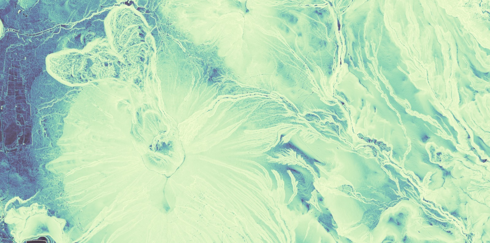
計算処理を応用すれば傾斜量や傾斜方位などの地形解析による可視化をしたり、曲率を計算してCS立体図(微地形図)を動的に生成することもできますが、計算が複雑になる程描画速度が遅くなるので注意が必要です。また、今回は解像度が固定されるGeoTIFFとは違い、ラスタータイルを使用してるので、ズームレベルに応じて適切なスケールファクターを設定するのが望ましいです。
傾斜量
傾斜方位
曲率+エッジ
おわりに
ラスタータイルのスタイリングも可能になり、Maplibreの地図表現が幅広くなると思います。addProtocol関数はタイルリクエストのたびに随時処理するため、同じような処理を毎回行わないように工夫したり、データのキャッシュを活用したりすることでパフォーマンスは軽減できます。
ですが、LeafletとWebGLで動的にラスタータイルを書き換える実例があり、こちらは地図レンダリングの部分のシェーダーを直接加工してるのでぬるぬる描画し、こちらの方が圧倒的にパフォーマンスが良いです。
MapLibreの場合、2024年11月現在では、内部のシェーダーに直接アクセスしてカスタムシェーダーを実装できるものはないため、フォークして中身のシェーダーを直接書き換えるしかなさそうです。Mapbox GL JSのhillshadeのシェーダーを直接加工した実例もあります。
もしくはMapLibreのglコンテキストに直接アクセスできるカスタムレイヤーでシェーダーによるタイルレンダリングを自作して実装するという手もあります。


