はじめに
日本Androidの会秋葉原支部ロボット部 Advent Calendar 2019 16日目です。
現在私はMaas関係のお仕事に従事させてもらってます。
その関係でちょっとCANに触れる機会がありましたので、ArduinoでCANに入門してみたいと思います。
CANとは
CAN(Contoroller Area Network)はもともとBoschが車載ネットワーク用に開発したものです。
Bus型のNW上に車の中にある各デバイス、ECUが接続されデータをやり取りしています。
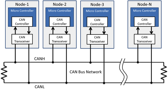
このNW上に各ECUはCANのパケットをブロードキャストで投げています。
各ECUはCANパケットを送るときに自分のIDをデータに付与して送ります。
パケットにはアービトレーションフィールドがデータフィールドの前にあり、データをやり取りするときの優先順位、重み付け使用します。
そうすることで車速やエンジンの回転数が運転席のダッシュボードで見れたり、OBD2のポートを利用して車の診断ができるわけです。
詳しい仕組みはルネサスのCAN入門書をご覧ください。
Arduinoでやってみよう
そんなCANですが車がないと試せないわけではありません。
CANに対応したモジュールとArduinoを用意してやってみましょう。
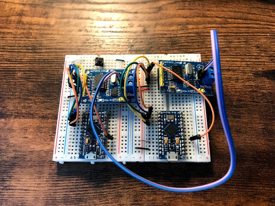
材料はaitendoのMCP2515モジュール×2と中華製promicro×2です。
送信側と受信側で2つ必要となります。
材料をブレットボード2つに配線します。
2つのモジュールは2本の線で結線します。CANは電位差で信号をやり取りするため、2本の線はH/Lとなっております。
スケッチ
以下のライブラリをインストールして、exampleにある受信と送信のプログラムを書き込んでみます。
・受信
# include <mcp_can.h>
# include <SPI.h>

long unsigned int rxId;
unsigned char len = 0;
unsigned char rxBuf[8];
char msgString[128];                        // Array to store serial string

# define CAN0_INT 2                              // Set INT to pin 2
MCP_CAN CAN0(10);                               // Set CS to pin 10


void setup()
{
  Serial.begin(115200);

  // Initialize MCP2515 running at 16MHz with a baudrate of 500kb/s and the masks and filters disabled.
  if(CAN0.begin(MCP_ANY, CAN_125KBPS, MCP_16MHZ) == CAN_OK)
    Serial.println("MCP2515 Initialized Successfully!");
  else
    Serial.println("Error Initializing MCP2515...");

  CAN0.setMode(MCP_NORMAL);                     // Set operation mode to normal so the MCP2515 sends acks to received data.

  pinMode(CAN0_INT, INPUT);                            // Configuring pin for /INT input

  Serial.println("MCP2515 Library Receive Example...");
}

void loop()
{
  if(!digitalRead(CAN0_INT))                         // If CAN0_INT pin is low, read receive buffer
  {
    CAN0.readMsgBuf(&rxId, &len, rxBuf);      // Read data: len = data length, buf = data byte(s)

    if((rxId & 0x80000000) == 0x80000000)     // Determine if ID is standard (11 bits) or extended (29 bits)
      sprintf(msgString, "Extended ID: 0x%.8lX  DLC: %1d  Data:", (rxId & 0x1FFFFFFF), len);
    else
      sprintf(msgString, "Standard ID: 0x%.3lX       DLC: %1d  Data:", rxId, len);

    Serial.print(msgString);

    if((rxId & 0x40000000) == 0x40000000){    // Determine if message is a remote request frame.
      sprintf(msgString, " REMOTE REQUEST FRAME");
      Serial.print(msgString);
    } else {
      for(byte i = 0; i<len; i++){
        sprintf(msgString, " 0x%.2X", rxBuf[i]);
        Serial.print(msgString);
      }
    }

    Serial.println();
  }
}
・送信
# include <mcp_can.h>
# include <SPI.h>

MCP_CAN CAN0(10);     // Set CS to pin 10

void setup()
{
  Serial.begin(115200);

  // Initialize MCP2515 running at 16MHz with a baudrate of 500kb/s and the masks and filters disabled.
  if(CAN0.begin(MCP_ANY, CAN_125KBPS, MCP_16MHZ) == CAN_OK) Serial.println("MCP2515 Initialized Successfully!");
  else Serial.println("Error Initializing MCP2515...");

  CAN0.setMode(MCP_NORMAL);   // Change to normal mode to allow messages to be transmitted
}

byte data[8] = {0x00, 0x01, 0x02, 0x03, 0x04, 0x05, 0x06, 0x07};

void loop()
{
  // send data:  ID = 0x100, Standard CAN Frame, Data length = 8 bytes, 'data' = array of data bytes to send
  byte sndStat = CAN0.sendMsgBuf(0x100, 0, 8, data);
  if(sndStat == CAN_OK){
    Serial.println("Message Sent Successfully!");
  } else {
    Serial.println("Error Sending Message...");
  }
  delay(100);   // send data per 100ms
}
スケッチを書いたら受信側のシリアルモニターを開きます。
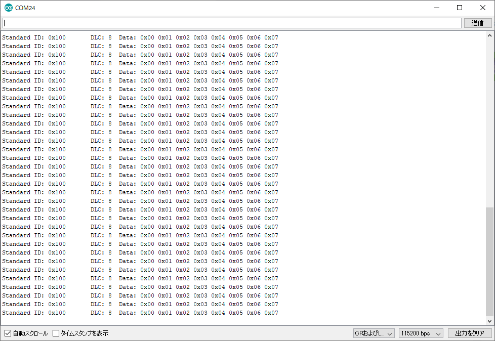
メッセージを受信できていればOKです。
送信側のプログラムで送っている、CANIDが0x100で0x00~0x07のデータが受信できていることがわかります。
というわけでArduinoでかんたんにCAN入門をしてみました。