日本Androidの会秋葉原支部ロボット部 Advent Calendar 2020 12日目です。
はじめに
micro:bitのv2が出たので買いました。

変更点についてはスイッチサイエンスのblogなどを見てもらうとして、v2ではnRF52833が使用されていてFlashやRAMのサイズ、スピーカやマイクの追加、Bluetooth 5などパワーアップしています。
スピーカやマイクの追加により声を使った作品もできるのではないでしょうか。
micro:bitのプログラミングでは公式サイトのブラウザでプログラミングするのが一般的と思いますが、ちょうどArduinoのライブラリが対応したのを見たので今回はArduinoでやってみたいと思います。
準備
とりあえずArduinosIDEを開いて環境設定>ボートマネージャでURLを貼り付けます。
https://sandeepmistry.github.io/arduino-nRF5/package_nRF5_boards_index.json

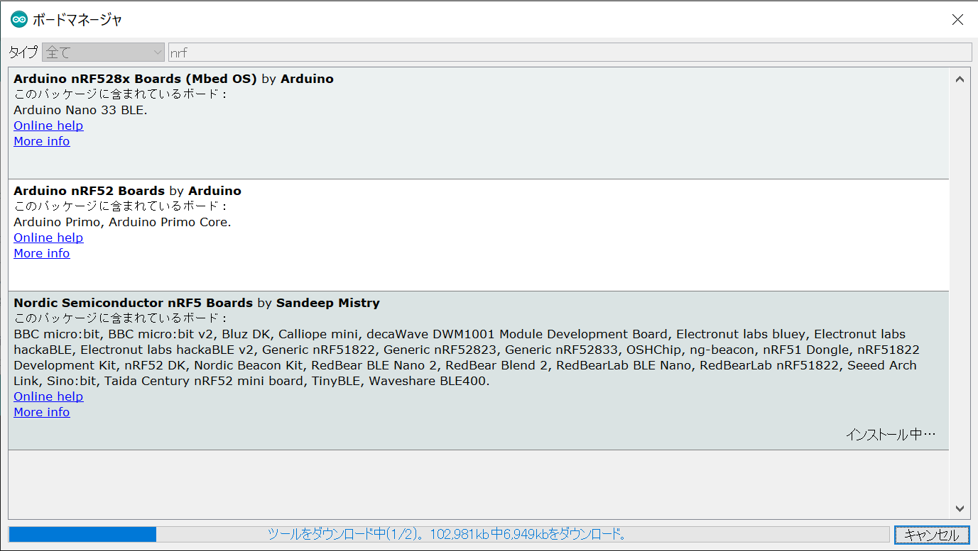
URLを貼ったらツール>ボード>ボードマネージャを開いてnrfと打って検索すると Nordic Semiconductor nrf5 Boards が出てくるのでインストールします。
インストールしたらボードで BBC micro:bit V2が選択できるようになれば準備完了です。
遊んでみよう
adafruitの記事のスケッチをコピペしてとりあえずLED光らせてみます。
const int COL1 = 3;
const int LED = 26;

void setup() {
  // because the LEDs are multiplexed, we must ground the opposite side of the LED
  pinMode(COL1, OUTPUT);
  digitalWrite(COL1, LOW);

  pinMode(LED, OUTPUT);
}

void loop(){
  digitalWrite(LED, HIGH);
  delay(500);
  digitalWrite(LED, LOW);
  delay(500);
}
You should see the top left LED blinking!
左上のLEDが...付かないじゃん...orz
公式サイトを見てみると、
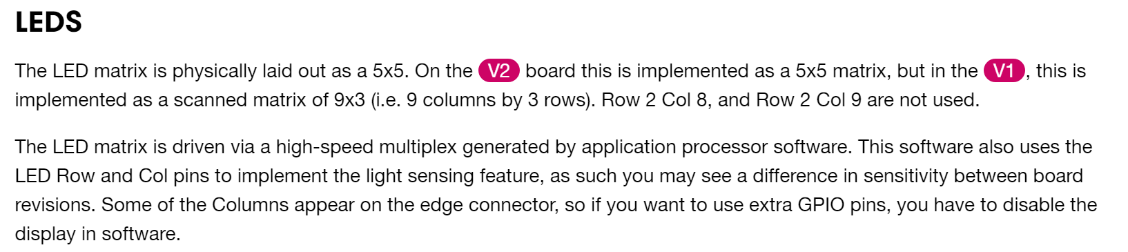
micro:bit v1ではLED matrixの9x3だったけど、v2は5x5に仕様が変わったようです。
v1とv2の変数定義を見てみると
const uint32_t g_ADigitalPinMap[] = {
  // 0 - 4
  3, // A0 - left pad
  2, // A1 - middle pad
  1, // A2 - right pad
  4, // A3 - COL1
  5, // A4 - COL2

  //省略

  // 17 + 18
  (uint32_t)-1, // 3.3V
  (uint32_t)-1, // 3.3V

  0,  // SCL
  30, // SDA

  25, // RX
  24, // TX

  7,  // COL4
  8,  // COL5
  9,  // COL6
  13, // ROW1
  14, // ROW2
  15, // ROW3
const uint32_t g_ADigitalPinMap[] = {
  // 0 - 4
  2,  // A0, LEFT PAD
  3,  // A1, MIDDLE PAD
  4,  // A2, RIGHT PAD
  31, // A3, COL3
  28, // A4, COL1

  // 21 - 25
  21, // ROW1
  22, // ROW2
  15, // ROW3
  24, // ROW4
  19, // ROW5
v1では col=3, row=26 を選択すれば左上のLEDが付いたところをv2ではcol=4, row=21と選択すればLEDが付きそうです。
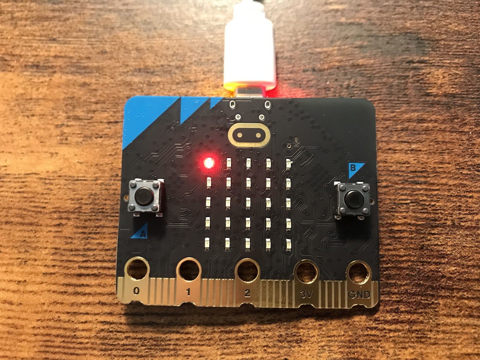
col=4, row=21にしてスケッチを書いてみるとLEDが点灯しました。
const int COL1 = 4;    //←4にする!!!
const int LED = 21;    //←21にする!!!

void setup() {
  // because the LEDs are multiplexed, we must ground the opposite side of the LED
  pinMode(COL1, OUTPUT);
  digitalWrite(COL1, LOW);

  pinMode(LED, OUTPUT);
}

void loop(){
  digitalWrite(LED, HIGH);
  delay(500);
  digitalWrite(LED, LOW);
  delay(500);
}
左上から右下まで1つずつ点滅させてみます。
const int cols[5] = {4, 7, 3, 6, 10};
const int rows[5] = {21, 22, 23, 24, 25};

void setup() {
  // because the LEDs are multiplexed, we must ground the opposite side of the LED
  Serial.begin(115200);

  for(int i=0; i < 5; i++) {
    pinMode(cols[i], OUTPUT);

    if(i==0) {
      digitalWrite(cols[i], LOW);
    } else {
      digitalWrite(cols[i], HIGH);
    }

    pinMode(rows[i], OUTPUT);
  }

}

void loop(){
  for(int i=0; i< 5; i++) {
    for(int j=0; j < 5; j++){
      digitalWrite(rows[i], HIGH);
      digitalWrite(cols[j], LOW);
      delay(200);
      digitalWrite(rows[i], LOW);
      digitalWrite(cols[j], HIGH);
      delay(200);
    }
  }
}
次はBluetoothで何かやりたいなーと思いましたが、ライブラリのほうでまだnrf52833は対応できておらずコンパイルエラーとなります。
現状、Arduino + micro:bit v2 + Bluetoothで遊ぶのは難しそうです...残念!😭😭😭
https://github.com/sandeepmistry/arduino-BLEPeripheral
https://github.com/sandeepmistry/arduino-BLEPeripheral/blob/master/src/nRF51822.h
※nrf52832に対応するcommitもあったので対応してくれると思いたいですが、最近活動がなさげです...
https://github.com/sandeepmistry/arduino-BLEPeripheral/commit/1cea5d24a6218515f180811837784c1742e10e0c