Lattice のツール iCEcube2 をつかう
久々に起動したらライセンスが切れているとのこと。ライセンスのページに行ってライセンスを発行してもらいます。確認事項の後メールでライセンスが送らてくるので所定の場所 (c:\lscc\License) にlicense.dat を置きます。
https://www.latticesemi.com/ja-JP/Support/Licensing

久々なので Lチカから始める
そして、試行錯誤の結果、Lattice のツールの使い方をすっかり忘れていることに気が付きました。初心に戻ることにしましょう。L チカから始めましょう。
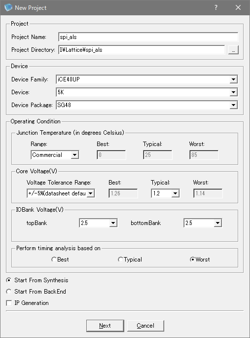
New Project
iCE40UP 向けにプロジェクトを作ります。
Lチカをコンパイルする
いやいやその前に Python で実行します。
from polyphony import testbench, module, is_worker_running
from polyphony.io import Port
from polyphony.timing import wait_value
from polyphony.typing import bit

@module
class Blink:
    def __init__(self, interval):
        self.led = Port(bit, 'out')
        self.interval = interval
        self.append_worker(self.main)

    def main(self):
        led_bit:bit = 1
        while is_worker_running():
            self.led(led_bit)
            led_bit = 1 - led_bit
            self._wait()

    def _wait(self):
        for i in range(self.interval // 2):
            pass


@testbench
def test(dut):
    v = 0
    for i in range(4):
        print("loop:", i)
        wait_value(1, dut.led)
        wait_value(0, dut.led)
    print("finished")

blink = Blink(125 * 1000 * 1000)
test(blink)
Python3 でシミュレート
> python3 blink.py
loop: 0
loop: 1
loop: 2
loop: 3
finished
コンパイル
> polyphony blink.py
> ls Blink_blink.v
Blink_blink.v
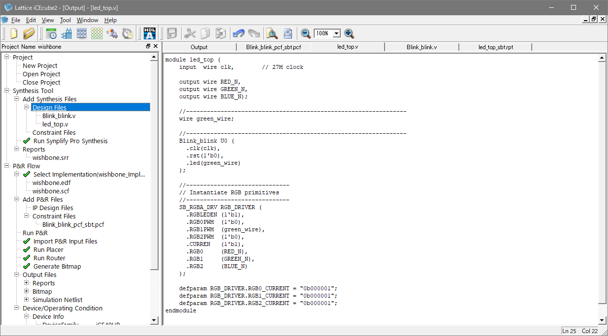
Design Files に追加する
TOP モジュールも追加
上の絵はすでに TOP モジュールも追加されています。TOP モジュールには LED のモジュールを追加しています。この辺は iCE40UP 特有の書き方なのでおまじないだと思って追加します。RGB0, RGB1 の PWM に 1'b0 を書いているので RED と BLUE は光りません。
module led_top (
    input  wire clk,        // 27M clock

    output wire RED_N,
    output wire GREEN_N,
    output wire BLUE_N);

    //----------------------------------------------------------------
    wire green_wire;

    //----------------------------------------------------------------
    Blink_blink U0 (
      .clk(clk),
      .rst(1'b0),
      .led(green_wire)
    );

    //------------------------------
    // Instantiate RGB primitives
    //------------------------------
    SB_RGBA_DRV RGB_DRIVER (
      .RGBLEDEN (1'b1),
      .RGB0PWM  (1'b0),
      .RGB1PWM  (green_wire),
      .RGB2PWM  (1'b0),
      .CURREN   (1'b1),
      .RGB0     (RED_N),
      .RGB1     (GREEN_N),
      .RGB2     (BLUE_N)
    );

    defparam RGB_DRIVER.RGB0_CURRENT = "0b000001";
    defparam RGB_DRIVER.RGB1_CURRENT = "0b000001";
    defparam RGB_DRIVER.RGB2_CURRENT = "0b000001";
endmodule
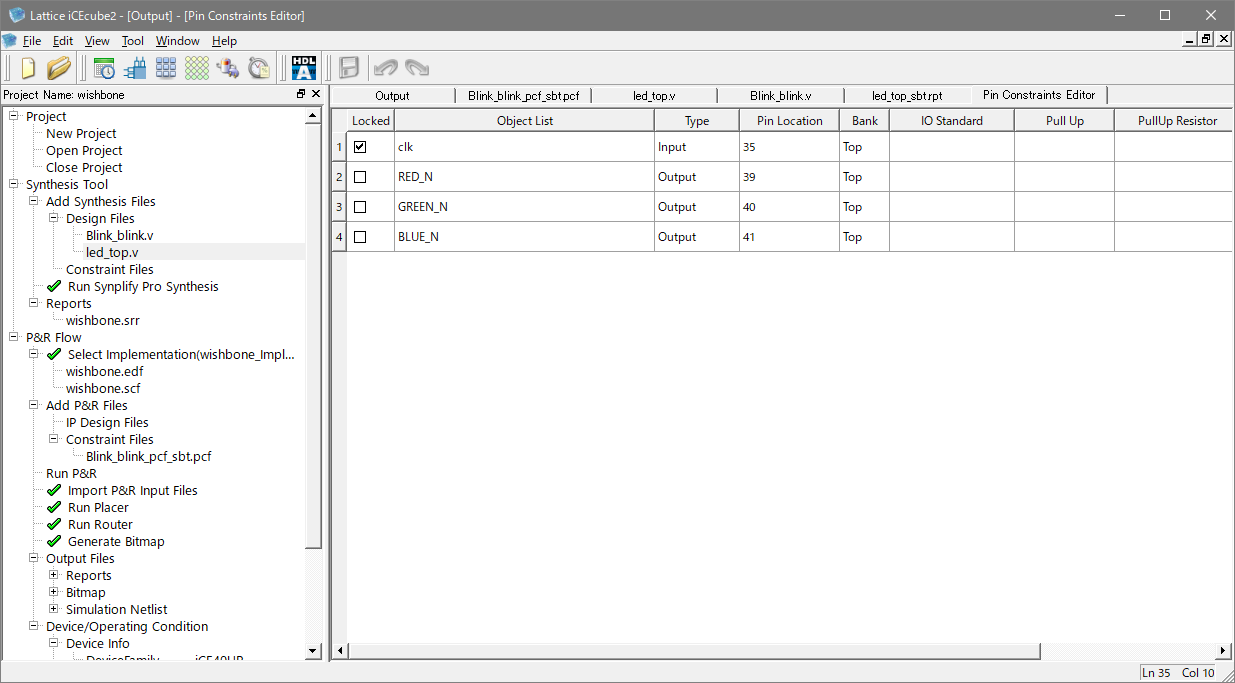
ピン配置も追加
Pin Constraints Editor をクリックするとエディターが出てくるので RBB の各ピンを設定します。
Bitmap ファイルを作る
あとは左の Run P&R を一つずつクリックしていけば合成できます。
ダウンロード
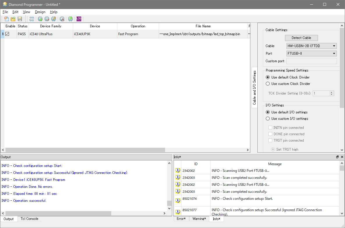
ダウンロードは Diamond Programmer という別のプログラムを起動します。
ボードをつなぐ
ボードをつないで J6 を PROG ICE にしておきます。
プログラムを指定する
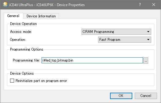
Device Properties ... から Progarmming file を指定します。
ダウンロード実行
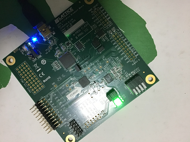
Program ボタンを押すとダウンロードが始まり見事に Green の LED がまぶしいくらいに点滅するでしょう。
