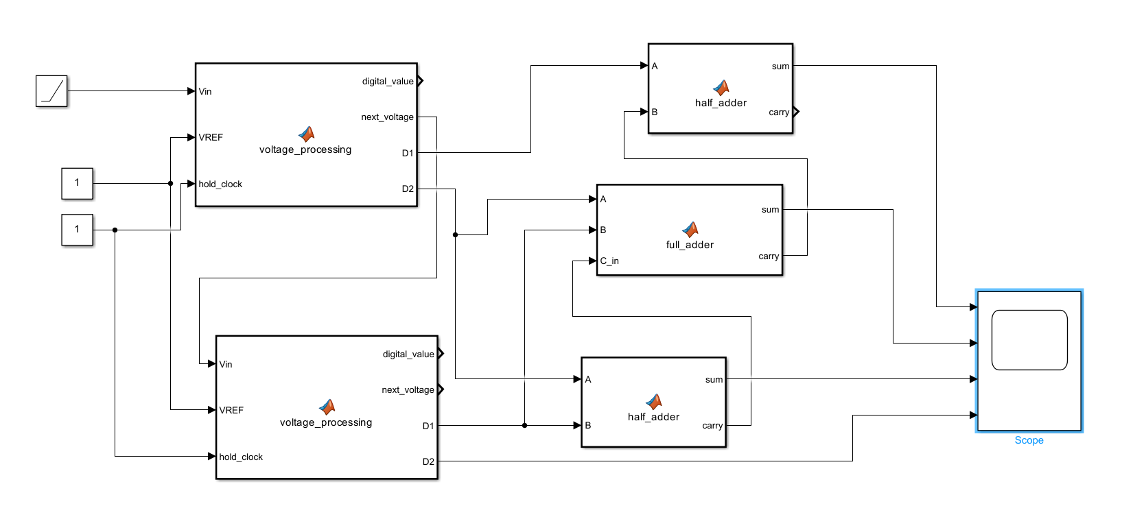
こちらの派生 MATLAB function
function [digital_value, next_voltage, D1, D2] = voltage_processing(Vin, VREF, hold_clock)
    % 1.5ビット探索アルゴリズム

    % 出力の初期化
    digital_value = 0;
    next_voltage = 0;
    D1 = 0;
    D2 = 0;

    % hold_clockが1であるか確認、そうでない場合は出力は0のまま
    if hold_clock == 1
        % 条件 1: 0 < Vin < 3/8 * VREF
        if Vin > 0 && Vin < (3/8) * VREF
            digital_value = 0;  % デジタル値は00(二進数)
            next_voltage = 2 * Vin;
            D1 = 0;  % D1を0に設定
            D2 = 0;  % D2を0に設定

        % 条件 2: 3/8 * VREF <= Vin < 4/8 * VREF
        elseif Vin >= (3/8) * VREF && Vin < (4/8) * VREF
            digital_value = 1;  % デジタル値は01(二進数)
            next_voltage = 2 * Vin - VREF / 2;
            D1 = 1;  % D1を1に設定
            D2 = 0;  % D2を0に設定

        % 条件 3: 4/8 * VREF <= Vin < 5/8 * VREF
        elseif Vin >= (4/8) * VREF && Vin < (5/8) * VREF
            digital_value = 1;  % デジタル値は01(二進数)
            next_voltage = 2 * Vin - VREF / 2;
            D1 = 0;  % D1を0に設定
            D2 = 1;  % D2を1に設定

        % 条件 4: 5/8 * VREF <= Vin < VREF
        elseif Vin >= (5/8) * VREF && Vin < VREF
            digital_value = 2;  % デジタル値は10(二進数)
            next_voltage = 2 * Vin - VREF;
            D1 = 1;  % D1を1に設定
            D2 = 1;  % D2を1に設定
        end
    end
end

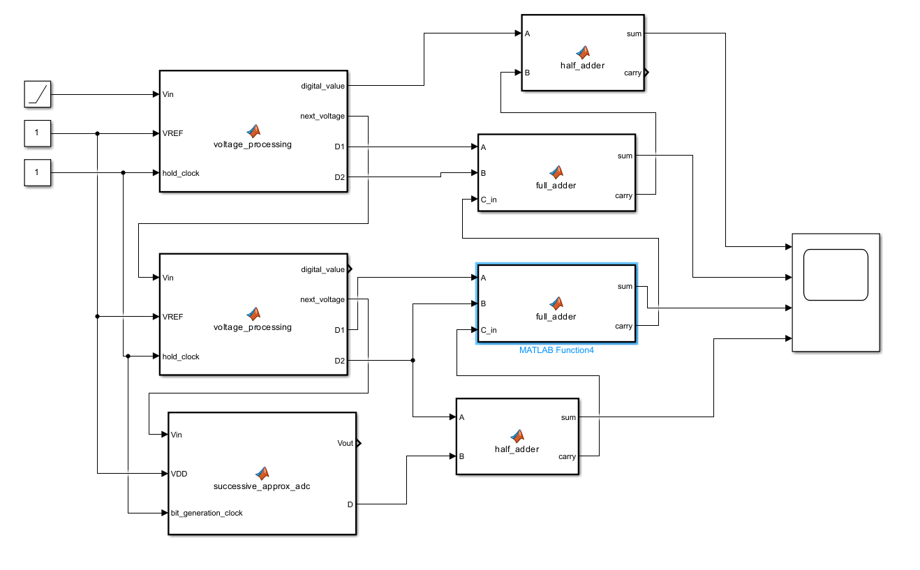
参考資料
% 逐次比較型ADC用MATLAB関数
function [Vout, D] = successive_approx_adc(Vin, VDD, bit_generation_clock)
    % 入力:
    %   Vin  - 入力電圧
    %   VDD  - 電源電圧
    %   bit_generation_clock    - ビット生成用のクロック (0 または 1)
    % 出力:
    %   Vout - 残差電圧
    %   D    - ビット出力 (0 または 1)

    % 基準電圧 VREF = VDD / 2
    VREF = VDD / 2;

    % クロックが0のとき出力はすべて0
    if bit_generation_clock == 0
        Vout = 0;
        D = 0;
        return; % クロックが0の場合、出力は更新されず終了
    end

    % クロックが1のとき、入力電圧に応じて計算
    if Vin > VREF
        Vout = 2 * (Vin - VREF); % VinがVREFより大きい場合
        D = 1;                   % ビット出力は1
    else
        Vout = 2 * Vin;          % VinがVREFより小さい場合
        D = 0;                   % ビット出力は0
    end
end

% クロックが0から1になると値を更新する関数
function y = fcn(u, VDD, bit_generation_clock)
    % fcn - クロックが0から1になるときに出力を更新する
    % 入力:
    %   u   - 入力電圧
    %   VDD - 電源電圧
    %   bit_generation_clock   - ビット生成用クロック信号 (0 または 1)
    % 出力:
    %   y   - 出力電圧 (Voutとビット出力)

    % 初期出力は全て0に設定
    persistent Vout D
    if isempty(Vout)
        Vout = 0;
        D = 0;
    end

    % クロックが0から1に変わったときのみ値を更新
    if bit_generation_clock == 1
        [Vout, D] = successive_approx_adc(u, VDD, bit_generation_clock);
    end

    % 結果を出力
    y = [Vout, D];
end
function [sum, carry] = half_adder(A, B)
    % 半加算器の入力AとB
    % A, B: 2つの入力ビット(0 または 1)

    % 和(Sum)の計算
    sum = xor(A, B);  % XOR演算によって和を求める

    % 繰り上がり(Carry)の計算
    carry = and(A, B);  % AND演算によって繰り上がりを求める
end
function [sum, carry] = full_adder(A, B, C_in)
    % フルアダの入力 A, B, C_in
    % A, B: 2つの入力ビット(0 または 1)
    % C_in: 前回の繰り上がりビット(0 または 1)

    % 和(Sum)の計算
    sum = xor(xor(A, B), C_in);  % (A XOR B) XOR C_in

    % 繰り上がり(Carry)の計算
    carry = or(and(A, B), and(C_in, xor(A, B)));  % (A AND B) OR (C_in AND (A XOR B))
end