


function [Vout, Bit] = fcn(Vin, Hold, VDD)
% Vref の計算
Vref = VDD / 2;
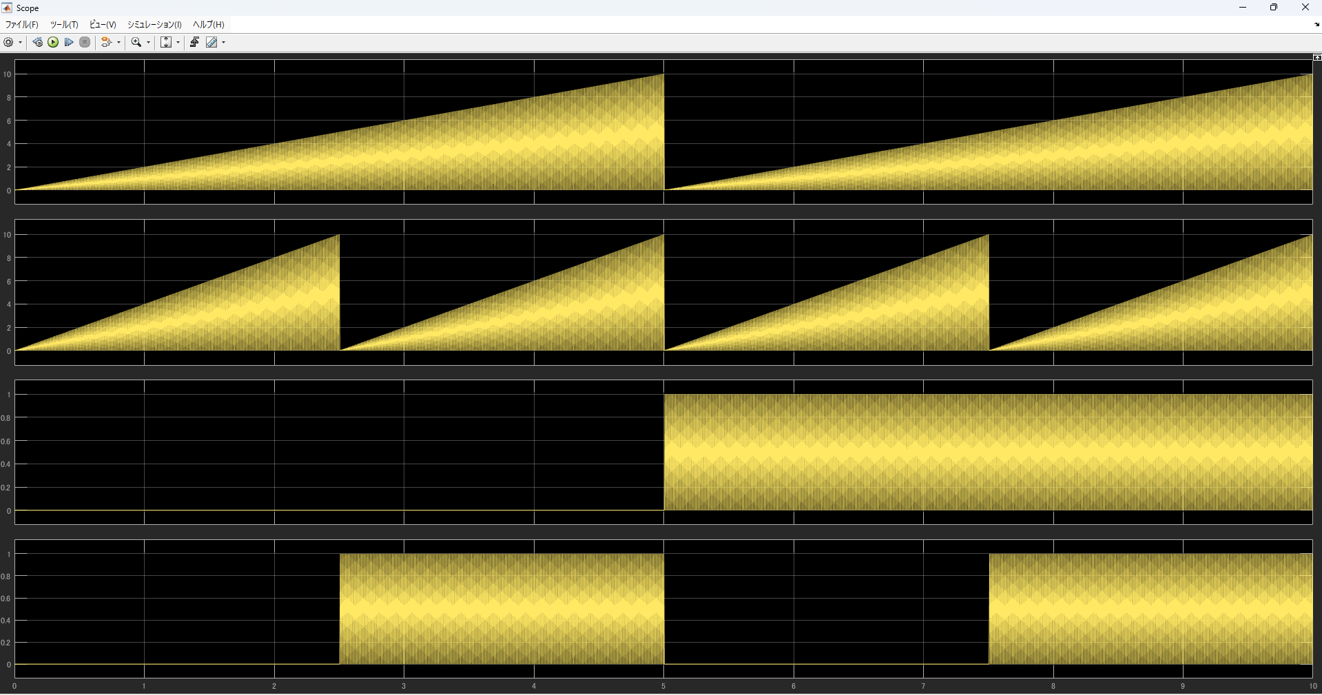
% Hold 信号が 0 のときは出力を 0 にする
if Hold == 0
Vout = 0;
Bit = 0;
else
% Vin が Vref より大きい場合
if Vin > Vref
Bit = 1;
Vout = 2 * (Vin - Vref);
% Vin が Vref 以下の場合
else
Bit = 0;
Vout = 2 * Vin;
end
end
end
おまけ 逐次比較ADC用にも使える
% 逐次比較型ADC用MATLAB関数
function [Vout, D] = successive_approx_adc(Vin, VDD, bit_generation_clock)
    % 入力:
    %   Vin  - 入力電圧
    %   VDD  - 電源電圧
    %   bit_generation_clock    - ビット生成用のクロック (0 または 1)
    % 出力:
    %   Vout - 残差電圧
    %   D    - ビット出力 (0 または 1)

    % 基準電圧 VREF = VDD / 2
    VREF = VDD / 2;

    % クロックが0のとき出力はすべて0
    if bit_generation_clock == 0
        Vout = 0;
        D = 0;
        return; % クロックが0の場合、出力は更新されず終了
    end

    % クロックが1のとき、入力電圧に応じて計算
    if Vin > VREF
        Vout = 2 * (Vin - VREF); % VinがVREFより大きい場合
        D = 1;                   % ビット出力は1
    else
        Vout = 2 * Vin;          % VinがVREFより小さい場合
        D = 0;                   % ビット出力は0
    end
end

% クロックが0から1になると値を更新する関数
function y = fcn(u, VDD, bit_generation_clock)
    % fcn - クロックが0から1になるときに出力を更新する
    % 入力:
    %   u   - 入力電圧
    %   VDD - 電源電圧
    %   bit_generation_clock   - ビット生成用クロック信号 (0 または 1)
    % 出力:
    %   y   - 出力電圧 (Voutとビット出力)

    % 初期出力は全て0に設定
    persistent Vout D
    if isempty(Vout)
        Vout = 0;
        D = 0;
    end

    % クロックが0から1に変わったときのみ値を更新
    if bit_generation_clock == 1
        [Vout, D] = successive_approx_adc(u, VDD, bit_generation_clock);
    end

    % 結果を出力
    y = [Vout, D];
end

% 電源電圧ありの非2進数型探索アルゴリズムのAD変換器
function [Vout, D] = binary_search_adc_with_vdd(Vin, VDD, bit_generation_clock)
    % 入力:
    %   Vin  - 入力電圧
    %   VDD  - 電源電圧
    %   bit_generation_clock    - ビット生成用のクロック (0 または 1)
    % 出力:
    %   Vout - 残差電圧
    %   D    - ビット出力 (0 または 1)

    % 基準電圧 VREF = VDD / 2
    VREF = VDD / 2;

    % 定数の定義(集積回路用に設定)
    beta = 1.98; % β = 1.98

    % クロックが0のとき出力はすべて0
    if bit_generation_clock == 0
        Vout = 0;
        D = 0;
        return; % クロックが0の場合、出力は更新されず終了
    end

    % クロックが1のとき、入力電圧に応じて計算
    if Vin > VREF
        D = 1; % VinがVREFより大きい場合、ビット出力は1
        Vout = beta * Vin + (1 - beta) * VREF; % D = 1の場合のVoutの計算
    else
        D = 0; % VinがVREF以下の場合、ビット出力は0
        Vout = beta * Vin - (1 - beta) * VREF; % D = 0の場合のVoutの計算
    end
end

% クロックが0から1になると値を更新する関数
function y = fcn(u, VDD, bit_generation_clock)
    % fcn - クロックが0から1になるときに出力を更新する
    % 入力:
    %   u   - 入力電圧
    %   VDD - 電源電圧
    %   bit_generation_clock   - ビット生成用クロック信号 (0 または 1)
    % 出力:
    %   y   - 出力電圧 (Voutとビット出力)

    % 初期出力は全て0に設定
    persistent Vout D
    if isempty(Vout)
        Vout = 0;
        D = 0;
    end

    % クロックが0から1に変わったときのみ値を更新
    if bit_generation_clock == 1
        [Vout, D] = binary_search_adc_with_vdd(u, VDD, bit_generation_clock);
    end

    % 結果を出力
    y = [Vout, D];
end


import numpy as np
import matplotlib.pyplot as plt

# 定数定義 / Define constants
beta = 2.0                     # ゲイン係数 / gain factor
Vref = 0.5                     # 基準電圧 / reference voltage
A = 50                         # オペアンプのゲイン(有限)/ op-amp finite gain

# 実効ゲインとh係数を計算 / Calculate effective gain and h
beta_eff = beta / (1 + beta / A)
h = 1 / (1 - A / (beta - 1))

# 入力ランプ波の生成 / Generate ramp input signal
Vin = np.linspace(0, 1, 500)

# 理想的な出力 / Ideal residual voltage
Vres_ideal = np.where(Vin >= Vref,
                      beta * Vin + (beta - 1) * Vref,
                      beta * Vin - (beta - 1) * Vref)

# 有限ゲインを考慮した出力 / Residual voltage with finite op-amp gain
Vres_real = np.where(Vin >= Vref,
                     beta_eff * Vin + (beta_eff - 1) * h * Vref,
                     beta_eff * Vin - (beta_eff - 1) * h * Vref)

# プロット / Plot
plt.figure(figsize=(10, 6))
plt.plot(Vin, Vres_ideal, label="Ideal Output", linestyle="--")
plt.plot(Vin, Vres_real, label=f"With Finite Gain (A={A})")
plt.axvline(x=Vref, color='gray', linestyle=':', label='Vref')
plt.xlabel("Input Voltage Vin")
plt.ylabel("Residual Voltage Vres")
plt.title("Switched-Capacitor Residual Voltage with Finite Gain Effect")
plt.legend()
plt.grid(True)
plt.show()