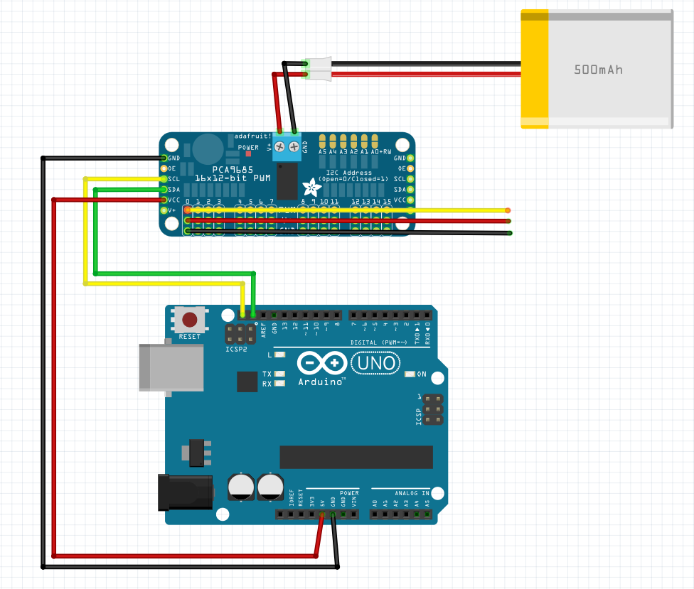
共立とアマゾンで購入したPCA9685の理論値と計測値を調べる。
ついでに、補正するプログラムを構築する。
接続
確認用プログラム
Arduinoを使用してPCA9685に接続したサーボモーターのPWMパルス幅をシリアルモニタから制御する。シリアルモニタに「1」を入力する度に、パルス幅が100ずつ増加する。
#include <Wire.h>                     // I2C通信ライブラリのインクルード
#include <Adafruit_PWMServoDriver.h>   // PCA9685ライブラリのインクルード

Adafruit_PWMServoDriver pwm = Adafruit_PWMServoDriver(0x40);  // PCA9685のI2Cアドレスを指定

#define SERVOMIN 500   // 最小パルス幅
#define SERVOMAX 3000   // 最大パルス幅

int Servo_pin = 0;      // サーボ接続ピンを0番に指定
int pulseWidth = SERVOMIN;  // 初期パルス幅を最小値に設定

void setup() {
  Serial.begin(9600);   // シリアル通信を初期化
  pwm.begin();          // PCA9685を初期化
  pwm.setPWMFreq(50);   // PWM周期を50Hzに設定
  delay(10);
}

void loop() {
  if (Serial.available() > 0) {              // シリアルモニタからの入力がある場合
    char input = Serial.read();              // 入力を読み取る
    if (input == '1') {                      // 入力が「1」の場合
      pulseWidth += 100;                     // パルス幅を100増加
      if (pulseWidth > SERVOMAX) {           // パルス幅が最大値を超えたら
        pulseWidth = SERVOMIN;               // 最小値に戻す
      }
      pwm.writeMicroseconds(Servo_pin, pulseWidth);  // 指定したパルス幅をサーボに送信
      Serial.print("Current Pulse Width: "); // 現在のパルス幅を表示
      Serial.println(pulseWidth);
    }
  }
}
詳細
-
シリアルモニタからの入力:シリアルモニタに「1」を入力すると、パルス幅が100増加する。パルス幅は
SERVOMAXを超えるとSERVOMINに戻る -
パルス幅の調整:
pwm.writeMicroseconds(Servo_pin, pulseWidth)によって、現在のパルス幅がサーボに送信される - シリアルモニタへの出力:現在のパルス幅がシリアルモニタに表示される
計測結果
| 理論値 | 共立:計測値 | アマゾン:計測値 |
|---|---|---|
| 500 | 491 | 469 |
| 600 | 587 | 561 |
| 700 | 688 | 657 |
| 800 | 784 | 749 |
| 900 | 885 | 845 |
| 1000 | 981 | 937 |
| 1100 | 1082 | 1033 |
| 1200 | 1178 | 1125 |
| 1300 | 1279 | 1221 |
| 1400 | 1375 | 1313 |
| 1500 | 1477 | 1410 |
| 1600 | 1572 | 1501 |
| 1700 | 1673 | 1598 |
| 1800 | 1770 | 1690 |
| 1900 | 1871 | 1786 |
| 2000 | 1967 | 1878 |
| 2100 | 2067 | 1974 |
| 2200 | 2164 | 2069 |
| 2300 | 2264 | 2164 |
| 2400 | 2361 | 2255 |
| 2500 | 2462 | 2352 |
| 2600 | 2557 | 2444 |
| 2700 | 2660 | 2540 |
| 2800 | 2756 | 2632 |
| 2900 | 2856 | 2730 |
| 3000 | 2952 | 2823 |
以降、共立で購入したPCA9685を用いる。
線形回帰を用いて補正関数を作成する
ズレを補正するための実測値から理論値を推定できるような関数を作成する。一般的には、実測値のデータを基に、補正関数を定義する。今回は、実測値が理論値とほぼ線形的に増加しているため、線形回帰によってズレを補正する。
Pythonで線形回帰を行い、補正関数を求める。
(sklearn,matplotlibをインストールしておくこと)
補正関数の計算
import numpy as np
from sklearn.linear_model import LinearRegression
import matplotlib.pyplot as plt

# 理論値と実測値のデータ
theoretical_values = np.array([500, 600, 700, 800, 900, 1000, 1100, 1200, 1300, 1400, 1500, 1600, 1700, 1800, 1900, 2000, 2100, 2200, 2300, 2400, 2500, 2600, 2700, 2800, 2900, 3000])
measured_values = np.array([491, 587, 688, 784, 885, 981, 1082, 1178, 1279, 1375, 1477, 1572, 1673, 1770, 1871, 1967, 2067, 2164, 2264, 2361, 2462, 2557, 2660, 2756, 2856, 2952])

# 1次元配列を2次元配列に変換
X = measured_values.reshape(-1, 1)
y = theoretical_values

# 線形回帰モデルを作成
model = LinearRegression()
model.fit(X, y)

# 回帰係数と切片を取得
slope = model.coef_[0]
intercept = model.intercept_

print(f"補正関数: 理論値 = {slope:.3f} * 実測値 + {intercept:.3f}")

# グラフ描画
plt.scatter(measured_values, theoretical_values, color='blue', label='実測値 vs 理論値')
plt.plot(measured_values, model.predict(X), color='red', label='回帰直線')
plt.xlabel('実測値')
plt.ylabel('理論値')
plt.legend()
plt.show()
実行結果
補正関数: 理論値 = 1.015 * 実測値 + 3.117
Arduinoコードでの補正
この補正関数をArduinoのコードに組み込んで、理論値に基づいたサーボの制御を行う。
#include <Wire.h>
#include <Adafruit_PWMServoDriver.h>

Adafruit_PWMServoDriver pwm = Adafruit_PWMServoDriver(0x40);

#define SERVOMIN 500    // 最小パルス幅
#define SERVOMAX 3000   // 最大パルス幅

int Servo_pin = 0;
int pulseWidth = SERVOMIN;

// 補正関数
float correctPulseWidth(float measured_value) {
  return 1.015 * measured_value + 3.117;
}

void setup() {
  Serial.begin(9600);
  pwm.begin();
  pwm.setPWMFreq(50);
  delay(10);
}

void loop() {
  if (Serial.available() > 0) {
    char input = Serial.read();
    if (input == '1') {
      pulseWidth += 100;
      if (pulseWidth > SERVOMAX) {
        pulseWidth = SERVOMIN;
      }

      float correctedPulse = correctPulseWidth(pulseWidth);  // 補正関数で修正
      pwm.writeMicroseconds(Servo_pin, correctedPulse);      // 修正されたパルス幅をサーボに送信
      Serial.print("Corrected Pulse Width: ");
      Serial.println(correctedPulse);
    }
  }
}
補正関数の役割
-
correctPulseWidth関数: 実測値を基に、理論値に補正する関。この関数がサーボに送られるパルス幅を調整する - シリアルモニタ: サーボの動作状況を確認するために、修正されたパルス幅がシリアルモニタに表示される
出力結果
Corrected Pulse Width: 612.12
Corrected Pulse Width: 713.62
Corrected Pulse Width: 815.12
Corrected Pulse Width: 916.62
Corrected Pulse Width: 1018.12
Corrected Pulse Width: 1119.62
Corrected Pulse Width: 1221.12
Corrected Pulse Width: 1322.62
Corrected Pulse Width: 1424.12
Corrected Pulse Width: 1525.62
Corrected Pulse Width: 1627.12
Corrected Pulse Width: 1728.62
Corrected Pulse Width: 1830.12
Corrected Pulse Width: 1931.62
Corrected Pulse Width: 2033.12
Corrected Pulse Width: 2134.62
表示された数値は、補正後のパルス幅 (Corrected Pulse Width) 。シリアルモニタに出力されたもので、補正関数を使って計算された結果。
補正関数 correctPulseWidth
理論値 = 1.015 * 実測値 + 3.117
シリアルモニタに表示された最初の値「612.12」は、補正関数によって以下のように計算されている。
- パルス幅が
600から開始する場合理論値 = 1.015 * 600 + 3.117 = 612.12
以下、他の値も同じ補正関数を使って計算された結果。たとえば、次の「713.62」は実測値が 700 だった時の補正後の理論値。
これらの値は、元の実測値 (100 ずつ増加する数値) に補正関数を適用して得られた結果。したがって、出力されたパルス幅は理論的に補正された値になっている。

