はじめに
はじめまして!iPhoneメンターのおいしんです。
Life is Tech ! Kanto Advent Calendar 2022の6日目ですね!
昨日はえーえすのカウントアプリを使って問題集を作ろう!でした。誰もが最初に作るアプリですが、様々な応用を知ることができてとっても面白かったです!
さて、この記事ではSVGファイルでベジェ曲線を描く際、ちょっとだけ直感的に描画する方法について考察していきます。ベジェ曲線の仕組み自体には触れませんが、「直感的なパラメータ → 制御点の座標」と変換する関数を作っていきます。
モチベーション
僕の趣味は展開図を描くことで、普段は紙に直線や曲線を描いてペーパークラフトを作ったりしています。(紙は直線に沿って折るだけでなく、実は曲線に沿って折ることもできます!とっても面白いのでぜひチャレンジしてみてください!)こちらの画像は、最近作った140cmくらいの貝殻のようなペーパークラフトの展開図の一部です。
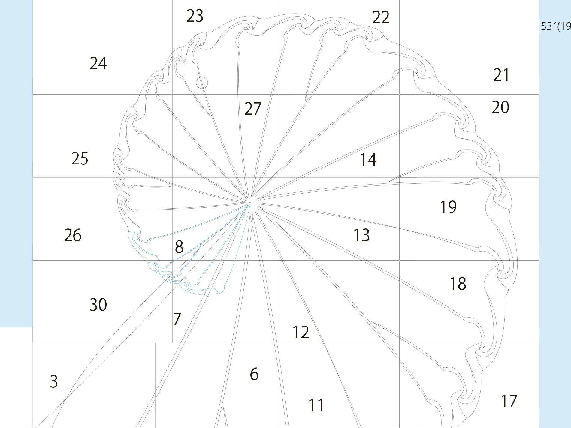
普段、展開図はIllustratorで描いています。ペーパークラフトを設計する際は、展開図を考えて実際に作り、イメージと比較して図面を手直しする、という試行錯誤が肝心なので、Illustratorでベクター画像の細かい編集ができるのは便利です。しかし、上の画像のように同じパーツが大きさや向きを変えて何度も登場する場合、変更が生じる度にパーツをコピーして配置しなおす…というのは大変です。
そこで、もしコードで展開図を管理できれば、同じパーツを繰り返し配置したり形を修正したりするのが簡単になるんじゃないかと考えました。加えて、曲線の膨らみ具合などを数字で管理できれば、今まで感覚で扱っていた部分を具体的な値で比較することができるようになります。
コードでお絵描きをする上で直線や円などは簡単に描くことができますが、問題となるのはベジェ曲線です。
こういった背景で、より面白いペーパークラフトを作るために、ベジェ曲線作画ツールを自作することにしました。
作りたいツール
TypeScriptが好きなので、普段よく使うReactでツールを作っていこうと思います。Fast Refreshがあるので、エディタから手を離さなくても横にブラウザを並べながらリアルタイムで線の具合を調整することができるというメリットもあります。
実は、ペーパークラフト制作とReactなどのコンポーネントベースの開発には共通点があります。Reactでコンポーネントを組み合わせてWebページを作るように、パーツごとに分割した展開図を組み合わせることで複雑なペーパークラフトを設計する手法を取ってみたら面白いのではないでしょうか?
Illustratorなどで後から編集できるようにしたいので、ベクター形式のSVGファイルを生成することを目標にします。SVGについてはMDNのドキュメントがわかりやすいです。
SVGファイルでは、アンカーポイントとハンドルの座標を指定することでベジェ曲線を描画できます。
<svg width="190" height="160" xmlns="http://www.w3.org/2000/svg">
  <path d="M 10 10 C 20 20, 40 20, 50 10" stroke="black" fill="transparent"/>
</svg>
上の例では、d=""の部分にパスの情報が入っていて、Mが始点、それ以降は3次ベジェ曲線のハンドル、ハンドル、終点の順に座標が並んでいます。ですが、いきなり制御点の座標を思い浮かべてSVGを書いていくのは難しそうです。
座標を指定する代わりに、直感的に想像できるパラメータを作ってベジェ曲線を定義し、それを制御点の座標に変換する関数を作ることができれば、簡単にベジェ曲線を作図できそうです。
直感的なパラメータ
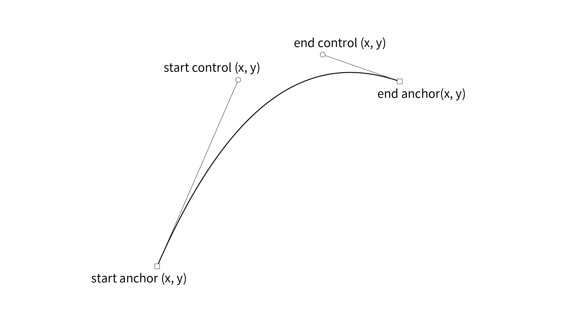
まず、最終的に出力する点に次のような名前をつけます。↓
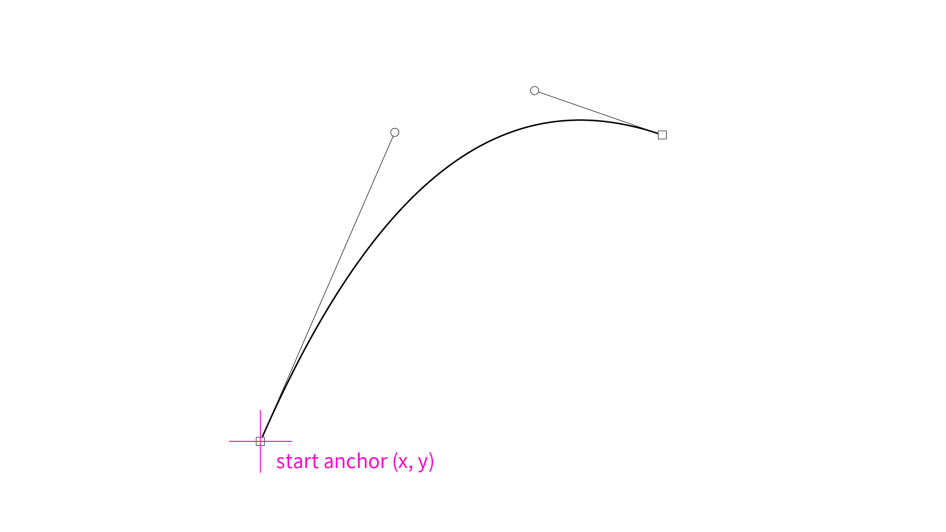
- start anchorを決める時
できるだけ座標を直接指定することなく曲線を定義したいのですが、どこか1点は基準が必要なので、start anchorの座標は自分で決めることにします。
では、我々が普段Illustrator等でベジェ曲線を描く時にどんなことを意識して描いているでしょうか?そこから直感的に曲線を定めるパラメータを考えていきます。
-
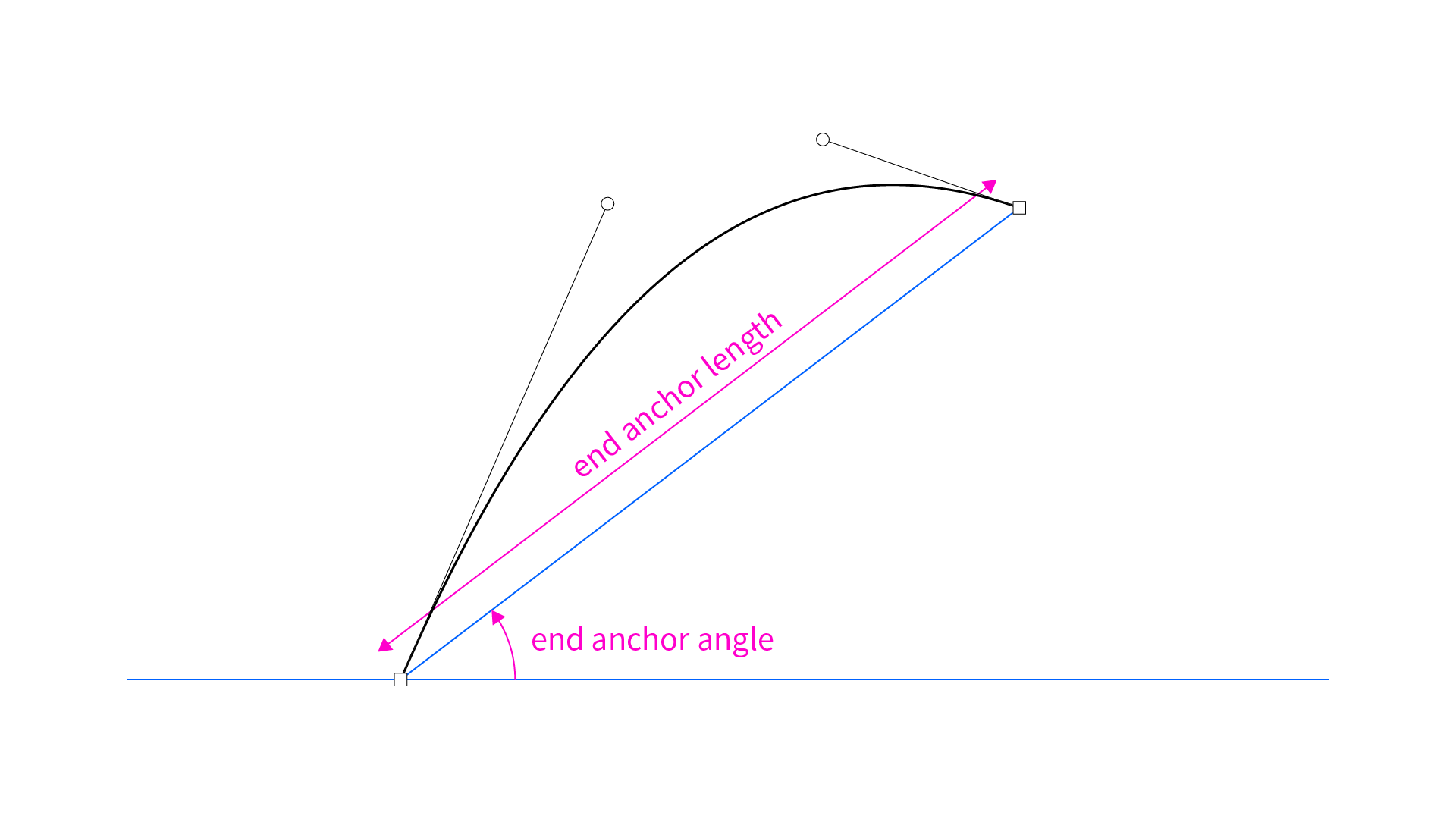
end anchorを決める時
Illustratorのペンツールなどでベジェ曲線を描く際、ハンドルと終点だと、終点の位置を先に考えるのではないでしょうか?どの方向にどのくらいの大きさの線を描くか、が一番直感的だと感じたので、start anchorからの角度と長さでend anchorの座標を求めることにします。end anchor lengthを大きくすれば、曲線自体のスケールも大きくなります。
-
start controlとend controlを決める時
ハンドルの制御点を考える時は、1. 曲線の膨らみ具合、2. 曲線の山の位置、の2つが重要だと思います。
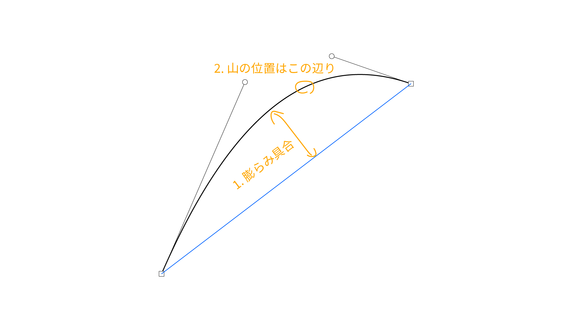
この2つの直感的なパラメータをハンドルの座標に変換する方法として、次のような方法を考えてみました。
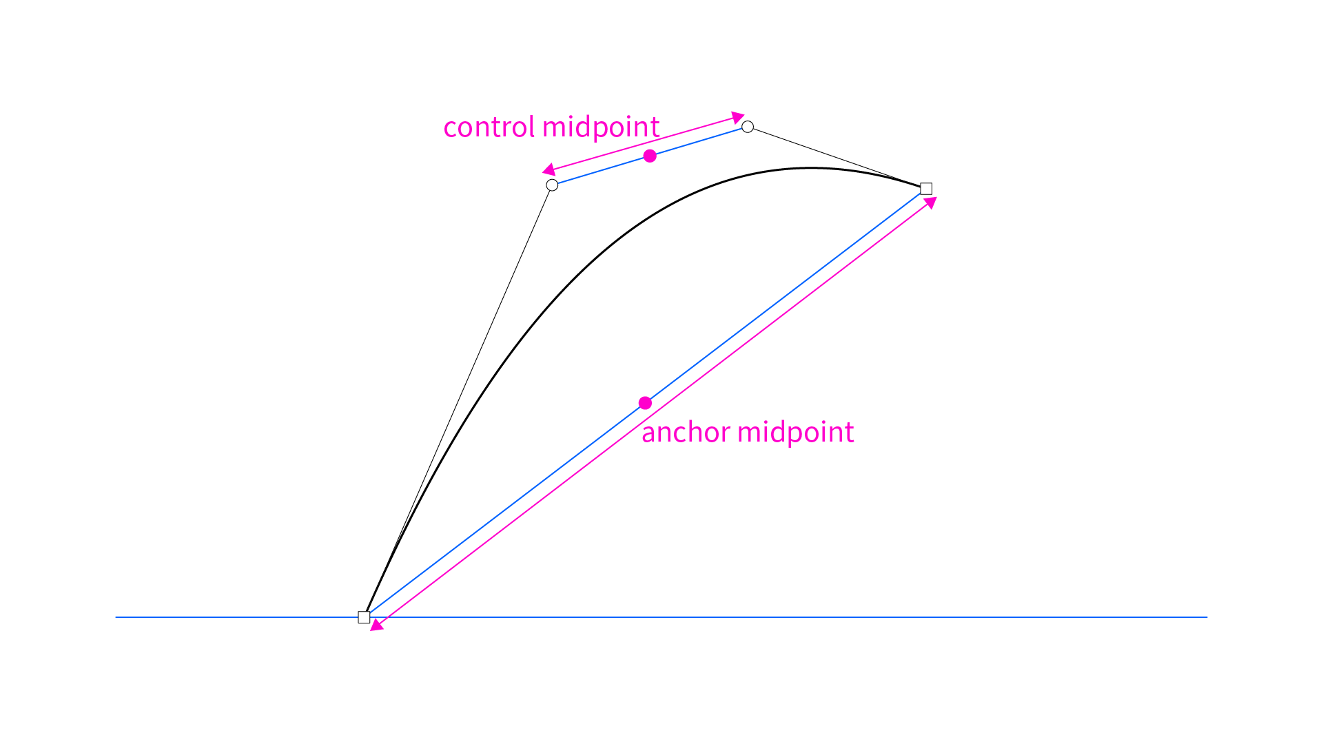
まず、アンカーポイントの中点とハンドルの中点を想定します。この時、anchor midpointの位置はすでに定まっていますが、control midpointはまだ決まっていません。↓
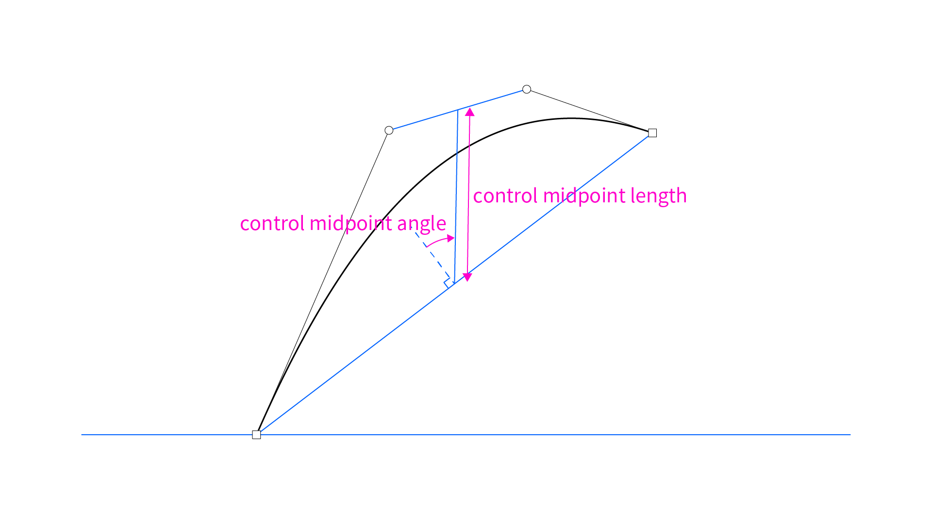
次に、anchor midpointからの角度と長さを指定することでcontrol midpointの座標を計算します。この時の角度は、アンカーポイント間を結んだ線の法線からずれた分の角度としました。こうすることで、control midpoint angleを0にすると曲線の山が真ん中あたりに、正の値にするとend anchor寄りの位置に、負の値にするとstart anchor寄りになります。また、control midpoint lengthの値で曲線の膨らみ具合を調整できます。負の値にすることで膨らみ方向を反転することもできます。↓
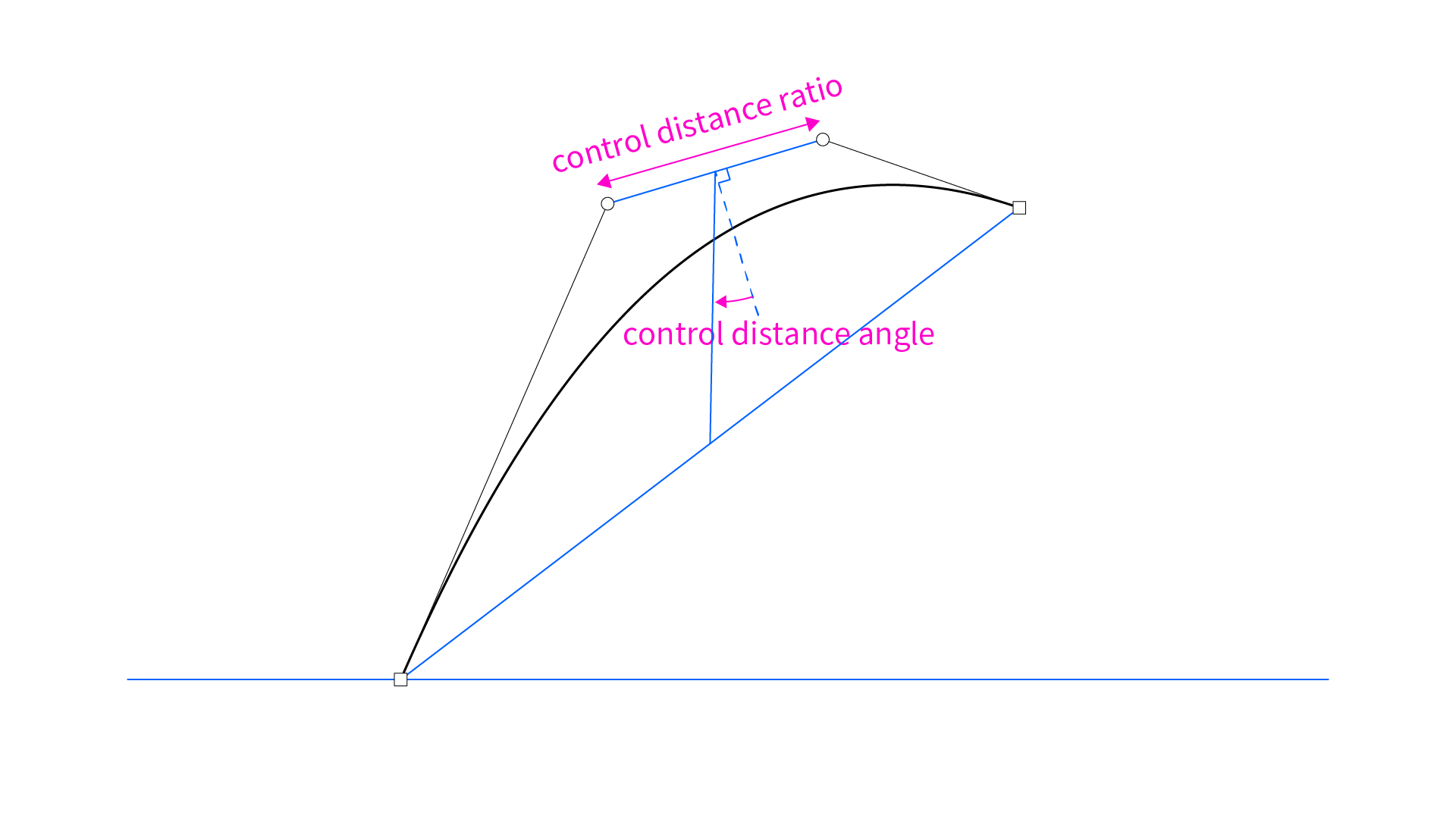
最後に、start controlとend controlの距離をcontrol distance ratio、ハンドル同士を結んだ線分の法線と中点同士を結んだ線分との角度のずれをcontrol distance angleとして指定します。control distance ratioは具体的な長さではなく、end anchor lengthに対する長さの比として表しています。1以下なら図のようにハンドルはハの字に、1以上なら逆ハの字になります。control distance angleは、0以上control midpoint angle以下に指定することで図のようなきれいな山形の曲線を描くことができますが、より大きなあるいは小さな角度を指定して歪んだ曲線を描くこともできます。↓
end anchor angle, end anchor length, control midpoint angle, control midpoint length, control distance ratio, control distance angleの6つのパラメータを使ってあらゆるベジェ曲線を表現できるようになりました。各制御点の座標を直接入力していたのと比べるとかなり直感的に作図できるようになったのではないでしょうか?
次は、いよいよ6つのパラメータを各制御点の座標に変換する関数を作っていきます。
制御点の座標に変換する関数
まずは型を定義していきます。
//座標の型
export type Vec2 = {
  x: number
  y: number
}
//関数の戻り値となる型
export type BezierPathInfo = {
  startAnchor: Vec2
  startControl: Vec2,
  endControl: Vec2,
  endAnchor: Vec2,
  anchorMidpoint: Vec2,
  controlMidpoint: Vec2
}
//関数の引数となる型

//start: start anchor point
//eaa: end anchor angle
//eal: end anchor length
//cma: control midpoint angle
//cml: control midpoint length
//cdr: ratio of control distance to end anchor length
//cda: control distance angle

type Props = {
  start: Vec2,
  controls: {
    eaa: number,
    eal: number,
    cma: number,
    cml: number,
    cdr: number,
    cda: number | "smooth"
  }[]
}
動的にSVGを生成するために、<svg>と<path>をカスタマイズしていきます。
type Props = {
  width?: number
  height?: number
  children?: React.ReactNode
}

//デフォルトのキャンバスサイズはA4
const Svg: React.FC<Props> = (props) => {
  return (
    <svg
      xmlns="http://www.w3.org/2000/svg"
      width={`${props.width ?? 3508}px`}
      height={`${props.height ?? 2480}px`}
      viewBox={`0 0 ${props.width ?? 3508} ${props.height ?? 2480}`}
      stroke="black"
      fill="transparent"
    >
      {props.children}
    </svg>
  )
}

export default Svg
type Props = {
  path: BezierPathInfo
  stroke?: string
  fill?: string
}

const SvgCubicBezier: React.FC<Props> = (props) => {
  const path = props.path
  const d = `M ${path.startAnchor.x} ${path.startAnchor.y} C ${path.startControl.x} ${path.startControl.y}, ${path.endControl.x} ${path.endControl.y}, ${path.endAnchor.x} ${path.endAnchor.y}`

  return (
    <path
      d={d}
      stroke={props.stroke ?? "black"}
      fill={props.fill ?? "transparent"}
    />
  )
}

export default SvgCubicBezier
いよいよProps => BezierPathInfoの関数を作ります。
export const bezierControlPoints = (props: Props): BezierPathInfo[] => {
  const { start, controls } = props

  let pathsInfo: BezierPathInfo[] = []
  for (let i = 0; i < controls.length; i++) {
    const control = controls[i]
    const startAnchor: Vec2 = pathsInfo.length === 0 ? start : pathsInfo[pathsInfo.length - 1].endAnchor
    const [endAnchorAngle, endAnchorLength, controlMidpointAngle, controlMidpointLength, controlDistanceAngle, controlDistanceRatio] = [control.eaa, control.eal, control.cma, control.cml, control.cda, control.cdr]

    const endAnchor: Vec2 = {
      x: startAnchor.x + cos(endAnchorAngle) * endAnchorLength,
      y: startAnchor.y - sin(endAnchorAngle) * endAnchorLength
    }

    const anchorMidpoint: Vec2 = midpoint(startAnchor, endAnchor)

    const controlMidpoint: Vec2 = {
      x: anchorMidpoint.x + cos(endAnchorAngle + (90 - controlMidpointAngle)) * controlMidpointLength,
      y: anchorMidpoint.y - sin(endAnchorAngle + (90 - controlMidpointAngle)) * controlMidpointLength
    }

    let controlDistance = 0
    if (controlDistanceRatio !== "smooth") {
      controlDistance = endAnchorLength * controlDistanceRatio
    } else {
       //後述
    }

    const startControl: Vec2 = {
      x: controlMidpoint.x + cos(180 - (controlMidpointAngle - endAnchorAngle + controlDistanceAngle)) * (controlDistance / 2),
      y: controlMidpoint.y - sin(180 - (controlMidpointAngle - endAnchorAngle + controlDistanceAngle)) * (controlDistance / 2)
    }

    const endControl: Vec2 = {
      x: controlMidpoint.x + cos(360 - (controlMidpointAngle - endAnchorAngle + controlDistanceAngle)) * (controlDistance / 2),
      y: controlMidpoint.y - sin(360 - (controlMidpointAngle - endAnchorAngle + controlDistanceAngle)) * (controlDistance / 2)
    }

    pathsInfo.push({ startAnchor: startAnchor, startControl: startControl, endControl: endControl, endAnchor: endAnchor, anchorMidpoint: anchorMidpoint, controlMidpoint: controlMidpoint })
  }

  return pathsInfo
}
使う時はこんな感じで配列にどんどん数値を入れていくことでベジェ曲線を繋いでいくことができます。<g>で囲んだ部分はグループ化されます。
const Example: React.FC = () => {
  const pathInfoGroups: BezierPathInfo[][] = [
    bezierControlPoints({
      start: { x: 1000, y: 2000 },
      controls: [
        { eaa: 40, eal: 1600, cma: 30, cml: 1000, cdr: 0.4, cda: 15 },
        //...
      ]
    }),
    //...
  ]

  return (
    <Svg>
      {pathInfoGroups.map((pathsInfo, index) => (
        <g key={index}>
          {pathsInfo.map((pathInfo, index) => (
              <SvgCubicBezier path={pathInfo} key={index} />
          ))}
        </g>
      ))}
    </Svg>
  )
}

export default Example
あとはダウンロードボタンなどを作って(参考にしたサイト)、
const Index: React.FC = () => {
  const svgContainerRef = useRef<HTMLDivElement>(null)

  const downloadSvg = () => {
    if (!svgContainerRef) { return }
    const svgElement = svgContainerRef.current?.querySelector("svg")
    const svgText = new XMLSerializer().serializeToString(svgElement as Node)
    const svgBlob = new Blob([svgText], { type: 'image/svg+xml;charset=utf-8' })
    const svgUrl = URL.createObjectURL(svgBlob)
    const a = document.createElement('a')
    a.href = svgUrl
    a.download = "image_A4.svg"
    document.body.appendChild(a)
    a.click()
    document.body.removeChild(a)
    URL.revokeObjectURL(svgUrl)
  }

  return (
    <div>
      <button onClick={downloadSvg}>Download</button>
      <div ref={svgContainerRef}>
        <Example />
      </div>
    </div>
  )
}

export default Index
ひとまず完成です!!!!
制御点や途中で出てきた中点なども表示してみました。
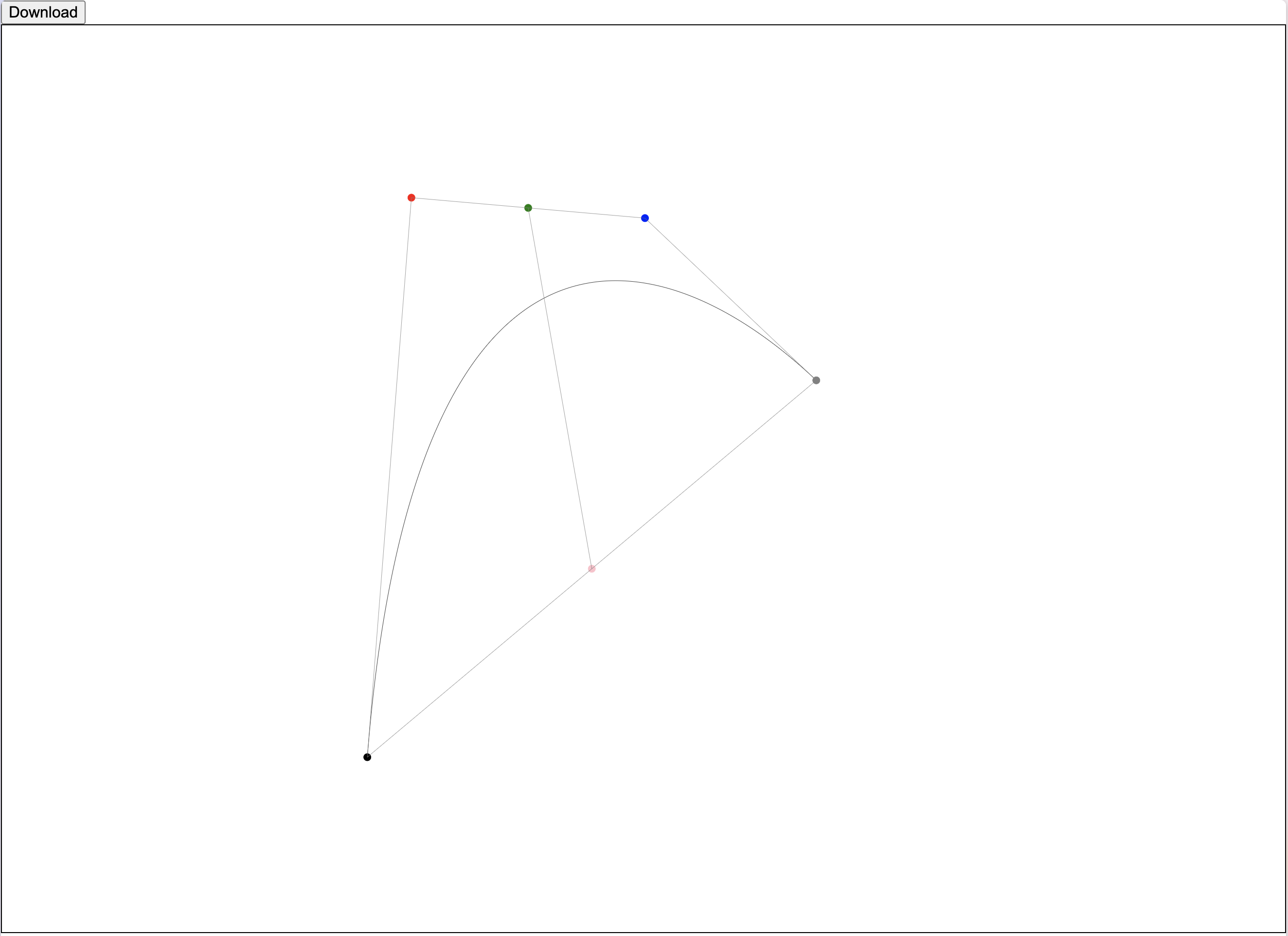
とりあえずベジェ曲線が書けるようになりました。しかし、曲線をたくさん描いていくとき、パスを滑らかに繋ぎたい場合が多いと思います。
SVGファイルを直接書く場合でも、Sコマンドを使うことでパスを滑らかに繋ぐことができますが、繋いでいるアンカーポイントから生える2本のハンドルが同じ長さになってしまいます。ハンドルを違う長さにできるとより便利になりそうですね。
6つの直感的なパラメータのうち4つはハンドルを定義するパラメータです。一つ前のパスから滑らかに繋がるようにしたい場合、それら4つのうち1つまでなら欠けていても計算で求めることができます。
ということで、control distance ratioに"smooth"を指定した場合、一つ前のパスから自動でハンドルの長さが計算されるようにしてみましょう。
    //
    let controlDistance = 0
    if (controlDistanceRatio !== "smooth") {
      controlDistance = endAnchorLength * controlDistanceRatio
    } else {
      const controlLineAngle = endAnchorAngle - controlMidpointAngle - controlDistanceAngle
      const extendedControlMidpoint: Vec2 = {
        x: controlMidpoint.x + cos(controlLineAngle) * 1000,
        y: controlMidpoint.y - sin(controlLineAngle) * 1000
      }
      const previousPath = pathsInfo[pathsInfo.length - 1]
      const smoothStartControl = intersection([previousPath.endControl, previousPath.endAnchor], [controlMidpoint, extendedControlMidpoint]) ?? { x: 0, y: 0 }
      controlDistance = distance(smoothStartControl, controlMidpoint) * 2
    }
    //
//2直線abとcdの交点
export const intersection = (ab: [Vec2, Vec2], cd: [Vec2, Vec2]): Vec2 | null => {
  const [a, b] = ab
  const [c, d] = cd

  if (a.x - b.x === 0) {
    const ratio_c = abs(a.x - c.x)
    const ratio_d = abs(a.x - d.x)
    const x = a.x
    if (ratio_c + ratio_d === 0) { return null }
    const y = c.y - ((d.y - c.y) * ratio_c / (ratio_c + ratio_d))
    return { x: x, y: y }
  }

  if (c.x - d.x === 0) {
    const ratio_a = abs(c.x - a.x)
    const ratio_b = abs(c.x - b.x)
    const x = c.x
    if (ratio_a + ratio_b === 0) { return null }
    const y = a.y - ((b.y - a.y) * ratio_a / (ratio_a + ratio_b))
    return { x: x, y: y }
  }

  const alpha = (a.y - b.y) / (a.x - b.x)
  const beta = (c.y - d.y) / (c.x - d.x)
  if (alpha - beta === 0) { return null }
  const x = ((c.y - beta * c.x) - (a.y - alpha * a.x)) / (alpha - beta)
  const y = alpha * x + a.y - alpha * a.x
  return { x: x, y: y }
}
例としてこのような数値と"smooth"を配列に入れてみると…
  //
  const pathInfoGroups: BezierPathInfo[][] = [
    bezierControlPoints({
      start: { x: 1000, y: 2200 },
      controls: [
        { eaa: 120, eal: 800, cma: 0, cml: 200, cdr: 0.4, cda: 20 },
        { eaa: 30, eal: 800, cma: 10, cml: 250, cdr: "smooth", cda: 10 },
        { eaa: 30, eal: 800, cma: 10, cml: -350, cdr: "smooth", cda: 10 },
        { eaa: 20, eal: 800, cma: 25, cml: 300, cdr: "smooth", cda: -10 }
      ]
    })
  ]
  //
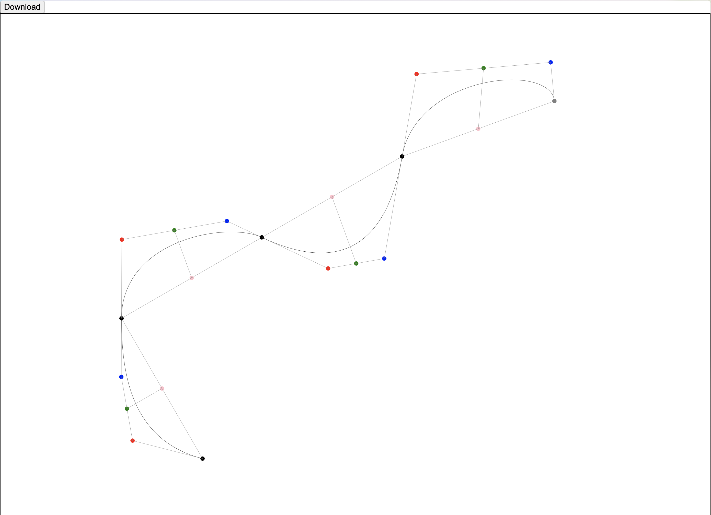
ベジェ曲線をどんどん滑らかに繋いでいくことができました!!
これで完成です!!
まとめ
コードから直感的にベジェ曲線をかく方法を考察してみました。これで展開図制作が捗りますね!!
初めてアドベントカレンダーに参加しましたが、みんなで一緒に作ってる感じが楽しかったです!
明日は らぞーなさんのFutureGatewayで展示した作品についてです!お楽しみに!!