概要
raspberry pi 1 model bの、node-redで、i2cを叩いて、OLEDを動かしてみた。
開発環境
raspberry pi 1 model b
raspbian 2016_09_23 jessie lite
準備
sudo aptitude install i2c-tools
sudo aptitude install python-smbus
sudo aptitude install python-pillow
raspi-config のAdvanced Option からi2cを有効化する。
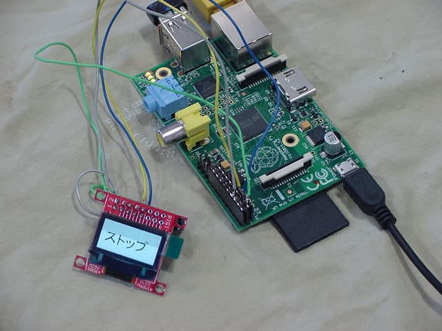
写真
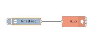
サンプルコード
[{"id":"2ca91c68.4c6684","type":"inject","z":"4f4f703e.a2a9d","name":"","topic":"","payload":"","payloadType":"date","repeat":"","crontab":"","once":false,"x":128,"y":421,"wires":[["3040db51.0c7da4"]]},{"id":"3040db51.0c7da4","type":"exec","z":"4f4f703e.a2a9d","command":"sudo python /home/pi/py/test7.py","addpay":true,"append":"","useSpawn":"","timer":"","name":"sudo","x":326,"y":421.5,"wires":[[],[],[]]}]
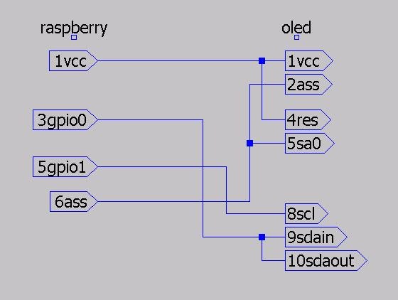
回路図
準備2
128×64の画像をつくる。
http://jsdo.it/ohisama1/yhxJ
サンプルコード
import smbus
import time
from PIL import Image

image = Image.open('canvas.png')
img = image.convert('1')
px = img.getdata()
oled = smbus.SMBus(1)
list0 = [0x21, 0, 127, 0x22, 0, 7]
for k in list0:
    block = []
    block.append(k)
    oled.write_i2c_block_data(0x3c, 0x0, block)

step = 1024
buf = [0] * 8 * step
of = [0, 128, 256, 384, 512, 640, 768, 896]
w = 128
j = 0
for y in range(0, 8 * step, step):
    i = y + w - 1
    while i >= y:
        buf[j] = (px[i] & 0x01) | (px[i + of[1]] & 0x01) << 1 | (px[i + of[2]] & 0x01) << 2 | (px[i + of[3]] & 0x01) << 3 | (px[i + of[4]] & 0x01) << 4 | (px[i + of[5]] & 0x01) << 5 | (px[i + of[6]] & 0x01) << 6 | (px[i + of[7]] & 0x01) << 7
        i -= 1
        j += 1

for i in range(64):
    block = []
    for j in range(16):
        b = i * 16 + j
        block.append(buf[b])
    oled.write_i2c_block_data(0x3c, 0x40, block)
print("ok")


