はじめに
本記事では、Raspberry Pi Pico H(以下、Pico)でLチカを実行するまでの手順をまとめます。
使用したハードウェア一覧
| 製品名 | 型名 | 個数 |
|---|---|---|
| Raspberry Pi 4B | SC0194(9) | 1 |
| Raspberry Pi Pico H (完成品) | SC0917 | 2 |
| USBケーブル USB2.0 Type-Aオス⇔マイクロBオス 0.5m A-microB | LDUC1231-0.5m | 1 |
| ブレッドボード EIC-801 | 165-40-4-8010 | 2 |
| コネクター付コード 3P 赤黄黒 1mmピッチ | DG01032-0038-02(M-11233)RYB | 1 |
| ジャンパーワイヤ | 165-012-000(EIC-J-L) | 1 |
リンクはすべて秋月電子通商の製品ページに対応しています。
上記に加えて、Raspberry Pi 4B に SSH 接続するための Windows PC も使用しています(表には記載していません)。
全体の構成図
今回の構成に登場するデバイスは以下の4つです。
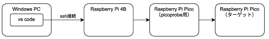
- Windows PC
開発用 PC です。Raspberry Pi 4B にリモート接続し、VS Code を使用して開発を行います。
※ VS Code のインストールや SSH 接続設定はこの記事では扱いません。 - Raspberry Pi 4B
開発サーバーとして動作します。プログラムのビルドやデバッグはこのマシン上で行います。 - Raspberry Pi Pico H(ターゲット)
実際にLチカプログラムを動作させるターゲットデバイスです。 - Raspberry Pi Pico H (picoprobe用)
デバッグ用の2台目の Pico です。picoprobeファームウェアを書き込むことで、もう1台のPicoに対するデバッグ・書き込みインターフェースとして機能します。
picoprobeがなくても開発は可能ですが、あるとデバッグやプログラム書き込みが便利になります。
専用のデバッグプローブも市販されていますが、今回は使用せず、2台目の Pico で代用しました。Pico が2台あれば、将来的に別の使い道も見つかるかもしれないと思ったからです。ただどちらを選んでも、操作性や価格面で大きな差はないと思います。
手順の全体像
1. picoprobeの作成
1.1 ファームウェアのダウンロード
picoprobe 用のファームウェア(debugprobe_on_pico.uf2)を、以下の公式 GitHub リリースページからダウンロードします。
raspberrypi/debugprobe - Releases
※2025年5月時点の最新版は v2.2.2 でした。
1.2 PicoとWindows PCを接続
Pico 本体の白いボタン(BOOTSEL)を押したまま、Windows PC に USB 接続します。
正しく認識されると、エクスプローラーに新しいドライブ(RPI-RP2など)が表示されます。
1.3 ファームウェアの書き込み
ダウンロードした debugprobe_on_pico.uf2 ファイルを、そのドライブへドラッグ&ドロップします。
1.4 接続の解除
書き込みが完了すると、自動的にドライブがエクスプローラーから消えます。
この状態になれば、USB から取り外して問題ありません。
これで、picoprobe の作成は完了です。
2. ハードウェアの接続
2.1 picoprobeとpico本体の接続
配線方法は 公式ドキュメント を参考にしました。
2.1 Raspberry Pi4Bとpicoprobeの接続
2台を USB 接続します。
以下の確認ができれば、正常に接続できています。
-
picoprobeの緑色の LED が点灯していること -
lsusbコマンドでDebugprobeが認識されていること
$ lsusb
Bus 002 Device 001: ID 1d6b:0003 Linux Foundation 3.0 root hub
Bus 001 Device 007: ID 2e8a:000c Raspberry Pi Debugprobe on Pico (CMSIS-DAP)
Bus 001 Device 002: ID 2109:3431 VIA Labs, Inc. Hub
Bus 001 Device 001: ID 1d6b:0002 Linux Foundation 2.0 root hub
これで、ハードウェアの接続は完了です。
この時点で、全体の構成図と一致しているはずです。
3. 開発環境の構築
3.1 開発環境へのログイン
VS Code を起動して、Raspberry Pi 4B にリモート接続します。
作業ディレクトリを作成します。
以下はホームディレクトリに作成する例です。
作業しやすい場所であれば、別のディレクトリでも問題ありません。
$ cd ~
$ mkdir pico
VS Code を閉じて、作業ディレクトリに改めて接続します。
3.2. openocdのインストールと実行確認
openocd のビルドに必要なパッケージをインストールします。
$ sudo apt update
$ sudo apt install -y cmake libtool libusb-1.0-0-dev libhidapi-dev automake texinfo build-essential
openocd のビルドとインストールをします。
ビルドには少し時間がかかります。
$ git clone https://github.com/raspberrypi/openocd.git --branch picoprobe
$ cd openocd
$ ./bootstrap
$ ./configure --enable-picoprobe --disable-werror
$ make -j4
$ sudo make install
adapter speed 5000 を cmsis-dap.cfg に追記します。
編集は vi 以外のエディタでも問題ありません。
$ sudo vi /usr/local/share/openocd/scripts/interface/cmsis-dap.cfg
ファイルの最終的な中身です。
$ cat /usr/local/share/openocd/scripts/interface/cmsis-dap.cfg
#
# ARM CMSIS-DAP compliant adapter
#
# http://www.keil.com/support/man/docs/dapdebug/
#

adapter driver cmsis-dap
adapter speed 5000
openocd を実行して、次のようなログが出力されたら成功です。
CTRL+Cで終了します。
$ openocd -f interface/cmsis-dap.cfg -f target/rp2040.cfg
Open On-Chip Debugger 0.11.0-g4f2ae61 (2025-05-05-16:44)
Licensed under GNU GPL v2
For bug reports, read
        http://openocd.org/doc/doxygen/bugs.html
adapter speed: 5000 kHz

Info : auto-selecting first available session transport "swd". To override use 'transport select <transport>'.
Info : Hardware thread awareness created
Info : Hardware thread awareness created
Info : RP2040 Flash Bank Command
Info : Listening on port 6666 for tcl connections
Info : Listening on port 4444 for telnet connections
Info : Using CMSIS-DAPv2 interface with VID:PID=0x2e8a:0x000c, serial=E663B03597601924
Info : CMSIS-DAP: SWD  Supported
Info : CMSIS-DAP: FW Version = 2.0.0
Info : CMSIS-DAP: Interface Initialised (SWD)
Info : SWCLK/TCK = 0 SWDIO/TMS = 0 TDI = 0 TDO = 0 nTRST = 0 nRESET = 0
Info : CMSIS-DAP: Interface ready
Info : clock speed 5000 kHz
Info : SWD DPIDR 0x0bc12477
Info : SWD DLPIDR 0x00000001
Info : SWD DPIDR 0x0bc12477
Info : SWD DLPIDR 0x10000001
Info : rp2040.core0: hardware has 4 breakpoints, 2 watchpoints
Info : rp2040.core1: hardware has 4 breakpoints, 2 watchpoints
Info : starting gdb server for rp2040.core0 on 3333
Info : Listening on port 3333 for gdb connections
adapter speed 5000 を設定ファイルに追加しないと、openocd 実行時に Error: CMSIS-DAP command CMD_DAP_SWJ_CLOCK failed. というエラーが発生しました。
3.3. VS Code拡張機能のインストール
拡張機能 cortex-debug をインストールします。
以下のリンク先からインストールできます。依存ライブラリも自動でインストールされます。
3.4. Raspberry Pi Pico SDKとサンプルの取得
Raspberry Pi Pico SDK を取得して、サブモジュールを初期化します。
$ cd ~/pico
$ git clone https://github.com/raspberrypi/pico-sdk.git
$ cd pico-sdk
$ git submodule update --init
Pico のサンプルコードを取得します。
$ cd ~/pico
$ git clone https://github.com/raspberrypi/pico-examples.git
最終的な pico ディレクトリの構成は次の通りです。
$ tree -a -L 1
.
├── openocd
├── pico-examples
├── pico-sdk
└── .vscode

6 directories, 0 files
以上で開発環境の構築は完了です!
4. Lチカのプログラムのビルドと実行
4.1 Lチカプログラムのビルド
サンプルコードは pico-examples ディレクトリに含まれています。
今回はその中の「blink」プログラムをビルドします。
$ cmake -S pico-examples -B pico-examples/build -DPICO_SDK_PATH=./pico-sdk
$ cmake --build pico-examples/build --target blink
ビルドが成功すると、以下のファイルが作成されます。
$ ls pico-examples/build/blink/
blink.bin  blink.dis  blink.elf  blink.elf.map  blink.hex  blink.uf2  CMakeFiles  cmake_install.cmake  Makefile  picotool
4.2 デバッグ設定
pico ディレクトリの中に、.vscode という隠しディレクトリがあるはずです。
そのディレクトリの直下に、launch.jsonを作成します。
$ cd ~/pico/.vscode
$ touch launch.json
このファイルには、Pico のデバッグ実行に必要な設定を記述します。
以下の内容を launch.json に保存してください。
※ パスは作業環境に合わせて、適宜変更してください。
{
  "version": "0.2.0",
  "configurations": [
    {
      "name": "Pico Debug",
      "type": "cortex-debug",
      "request": "launch",
      "executable": "${workspaceFolder}/pico/pico-examples/build/blink/blink.elf",
      "cwd": "${workspaceFolder}",
      "servertype": "openocd",
      "device": "RP2040",
      "configFiles": [
        "interface/cmsis-dap.cfg",
        "target/rp2040.cfg"
      ],
      "runToEntryPoint": "main",
      "svdFile": "${workspaceFolder}/pico/pico-sdk/src/rp2040/hardware_regs/RP2040.svd",
      "gdbPath": "/usr/bin/gdb-multiarch"
    }
  ]
}
4.3 デバッグ実行
VS Code の「実行とデバッグ」ビューから Pico Debug を選択し、▶ボタン(または F5 キー)でデバッグを開始します。

プログラムは main 関数に到達したあと一時停止します。
これは、launch.json の設定 "runToEntryPoint": "main" によるものです。
そのまま続行ボタン(またはF5キー)を押したら、プログラムが進行します。
Pico 上で LED が点滅したら、成功です!

4.4 Flashへの書き込み
デバッグ中はプログラムがRAM上で動作しているため、デバッグを終了するとプログラムも停止してしまいます。
そこで、プログラムをPicoの内蔵Flashに書き込みます。
$ cd ~/pico/pico-examples/build/blink
$ openocd -f interface/cmsis-dap.cfg -f target/rp2040.cfg -c "program blink.bin 0x10000000 verify reset exit"
手軽に書き込みができるのも picoprobe の強みですね!
これで、デバッグ終了後もLEDの点滅が続きます。
まとめ
今回は Raspberry Pi Pico H で LED を点滅させるまでの手順をまとめました。
この記事が誰かの役に立てれば幸いです。
次回は4章でビルドしたプログラムの中身を見ていきたいと思います。
謝辞
この記事を執筆するにあたり、以下の記事には大変お世話になりました。