きっかけ
出先でシングルボードコンピュータにsshするとき、出先のネットワークでのipアドレスがわからず不便だった。
ipを確認するためだけにモニタを持ち運ぶのは不可能なので、起動時にLCDにipを表示するか~ということでやってみた。
ハードウェアについてはまるっきりの初心者です。
ハードの準備
LCD
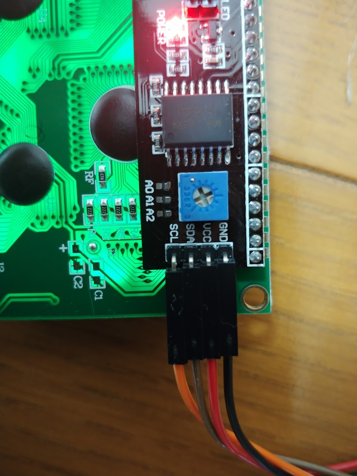
今回購入したLCDはこちら。画面サイズは20x4、5V駆動にした。
最初からI2Cインターフェースが半田付けされているタイプなので、はんだ付けが苦手な私にぴったりだった。
20x4 キャラクタLCDディスプレイモジュール/I2C(IIC,TWI)シリアルインタフェース/バックライト付き/HD44780コントローラ(2004 LCD 5V青)
ジャンパー線
I2Cで制御する場合、たったの4本しか必要ない。
今回は制御に使うRock64のGPIOがオス、I2Cインターフェースもオスだったのでメス-メスのジャンパー線を使った。
3.3V-5Vコンバーター(任意)
LCDは3.3V駆動と5V駆動の二種類があり、GPIOの出力も3.3Vや5Vなどの種類がある。
異なる場合は論理レベルを相互変換するコンバーターが必要。
今回は使用しなかった。
ソフトの準備
モジュールファイルを編集
sudo vim /etc/modules
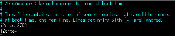
末尾に二行、このように追記すればOK
モジュールファイルを適応させるため再起動が必要。
必要なパッケージのインストール
sudo apt-get install python-smbus
sudo apt-get install python3-smbus
sudo apt-get install i2c-tools
これでi2cdetectやi2csetなどのコマンドを使ってi2c通信をできるようになります。
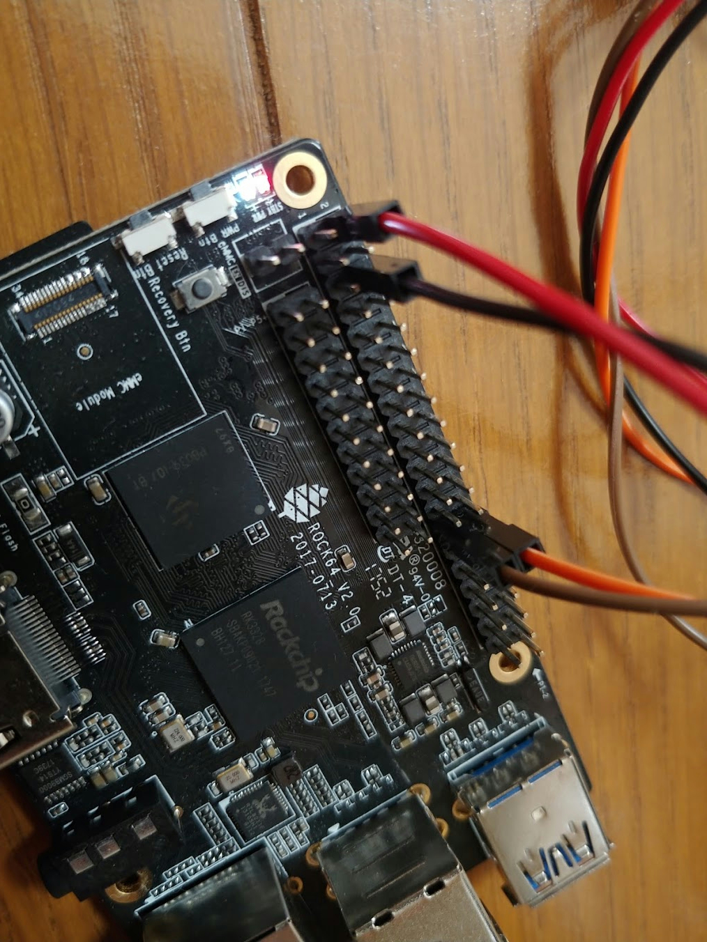
LCDディスプレイをつなぐ
GPIOに触る前にボードの電源を落としてください。
ここで大きな落とし穴があります!!!
Rock64 ハードウェア情報を参照すると、このように書いてあります。
Pins P3 and P5 are not configured as an i2c buss (no /dev/i2c-0).
Pins P27 and P28 operate as an i2c-buss, /dev/i2c-1, including pull-up resistors 2.2kΩ. Address 0x18 is reserved for the PMIO but others can be used.
より、Rock64の場合、I2C通信に使うGPIOは27, 28ピンでなくてはなりません。私は3, 5ピンを使用しておりずっと悩んでいました。
I2Cインターフェースのピン4本とRock64のGPIOの対応図です。ラズパイやその他の方はGPIOピンを確認して読み替えてください。
| IC2インターフェース | GPIO | Rock64のピン番号 |
|---|---|---|
| GND | GND | 6, 9, 14, 20, 25, 30, 34, 39など |
| VCC | VCC5V | 2, 4 |
| SDA | I2C-SDA | 27 |
| SCL | I2C-SCL | 28 |
スレーブアドレスを探す
I2C通信では制御される機器(スレーブ)は機器固有のアドレスを持っています。今回LCDのI2Cインターフェースとして接続されているPCF8574Tがスレーブになります。PCF8574Tのデータシートよりスレーブアドレスは0x27となるそうですが、ちゃんと確かめる必要があります。
まずI2Cのバスを見つけます。
rock64@rock64:~$ i2cdetect -l
i2c-1   unknown         rk3x-i2c                                N/A
i2c-4   unknown         DesignWare HDMI                         N/A
i2c-1とi2c-4がヒットしたので、それぞれに対して調べていきます。
rock64@rock64:~$ sudo i2cdetect -y 1
     0  1  2  3  4  5  6  7  8  9  a  b  c  d  e  f
00:          -- -- -- -- -- -- -- -- -- -- -- -- --
10: -- -- -- -- -- -- -- -- UU -- -- -- -- -- -- --
20: -- -- -- -- -- -- -- 27 -- -- -- -- -- -- -- --
30: -- -- -- -- -- -- -- -- -- -- -- -- -- -- -- --
40: -- -- -- -- -- -- -- -- -- -- -- -- -- -- -- --
50: -- -- -- -- -- -- -- -- -- -- -- -- -- -- -- --
60: -- -- -- -- -- -- -- -- -- -- -- -- -- -- -- --
70: -- -- -- -- -- -- -- --
rock64@rock64:~$ sudo i2cdetect -y 4
     0  1  2  3  4  5  6  7  8  9  a  b  c  d  e  f
00:          -- -- -- -- -- -- -- -- -- -- -- -- --
10: -- -- -- -- -- -- -- -- -- -- -- -- -- -- -- --
20: -- -- -- -- -- -- -- -- -- -- -- -- -- -- -- --
30: 30 -- -- -- -- -- -- -- -- -- -- -- -- -- -- --
40: -- -- -- -- -- -- -- -- -- -- -- -- -- -- -- --
50: -- -- -- -- -- -- -- -- -- -- -- -- -- -- -- --
60: -- -- -- -- -- -- -- -- -- -- -- -- -- -- -- --
70: -- -- -- -- -- -- -- --
UUと表示されているものはCPUなどに使われてるやつなので関係ないです。この場合LCDのアドレスはバス1の0x27、バス4の0x30のどちらかということがわかります。
データシートと突き合わせてLCDのスレーブアドレスが0x27だとわかったので、さっそくプログラミングをしていきましょう。
とりあえずLCDを点灯させるプログラム
wget http://osoyoo.com/driver/i2clcda.py
sudo python i2clcda.py
このプログラムのIC2_ADDRの部分を自分のLCDのスレーブアドレスにして、IC2_WIDTHを自分の使っているLCDのサイズにすれば動くはずです。
I2Cを使うのでsudoを付ける必要があります。
上手く表示されない場合、I2Cインターフェースの裏の、画面の濃度を調整するツマミをドライバーで回すと文字が見えるようになるかもしれません。
ipを表示するやつ
ソースコード貼り付けちゃいます。
このコードは20x4のLCDで動くことを想定しているので、それ以外のサイズの場合は表示する文字列を弄ってください。
import uuid
import subprocess
import re


def get_mac_address():
    node = uuid.getnode()
    mac = uuid.UUID(int=node)
    addr = mac.hex[-12:]
    addr_with_minus = "-".join([(i + j) for (i, j) in zip(addr[::2], addr[1::2])])
    return addr_with_minus


def get_ip_address():
    proc = subprocess.check_output(["ifconfig", "eth0"])
    proc = str(proc)
    pattern = r'(?<![\.\d])(?:\d{1,3}\.){3}\d{1,3}(?![\.\d])'
    repatter = re.compile(pattern)
    for stri in proc.splitlines():
        if "inet " in stri:
            result = repatter.search(stri)
            return result.group()
        else:
            continue
import smbus
import time
# Define some device parameters
I2C_ADDR = 0x27 # I2C device address, if any error, change this address to 0x3f
LCD_WIDTH = 20 # Maximum characters per line
# Define some device constants
LCD_CHR = 1 # Mode - Sending data
LCD_CMD = 0 # Mode - Sending command
LCD_LINE_1 = 0x80 # LCD RAM address for the 1st line
LCD_LINE_2 = 0xC0 # LCD RAM address for the 2nd line
LCD_LINE_3 = 0x94 # LCD RAM address for the 3rd line
LCD_LINE_4 = 0xD4 # LCD RAM address for the 4th line
LCD_BACKLIGHT_ON = 0x08 # On
LCD_BACKLIGHT_OFF = 0x00 # Off
LCD_BACKLIGHT = LCD_BACKLIGHT_ON
ENABLE = 0b00000100 # Enable bit
# Timing constants
E_PULSE = 0.0005
E_DELAY = 0.0005
# Open I2C interface
# bus = smbus.SMBus(0) # Rev 1 Pi uses 0
bus = smbus.SMBus(1) # Rev 2 Pi uses 1
def lcd_init():
# Initialise display
lcd_byte(0x33, LCD_CMD) # 110011 Initialise
lcd_byte(0x32, LCD_CMD) # 110010 Initialise
lcd_byte(0x06, LCD_CMD) # 000110 Cursor move direction
lcd_byte(0x0C, LCD_CMD) # 001100 Display On,Cursor Off, Blink Off
lcd_byte(0x28, LCD_CMD) # 101000 Data length, number of lines, font size
lcd_byte(0x01, LCD_CMD) # 000001 Clear display
time.sleep(E_DELAY)
def lcd_byte(bits, mode):
# Send byte to data pins
# bits = the data
# mode = 1 for data
# 0 for command
bits_high = mode | (bits & 0xF0) | LCD_BACKLIGHT
bits_low = mode | ((bits << 4) & 0xF0) | LCD_BACKLIGHT
# High bits
bus.write_byte(I2C_ADDR, bits_high)
lcd_toggle_enable(bits_high)
# Low bits
bus.write_byte(I2C_ADDR, bits_low)
lcd_toggle_enable(bits_low)
def lcd_toggle_enable(bits):
# Toggle enable
time.sleep(E_DELAY)
bus.write_byte(I2C_ADDR, (bits | ENABLE))
time.sleep(E_PULSE)
bus.write_byte(I2C_ADDR, (bits & ~ENABLE))
time.sleep(E_DELAY)
def lcd_string(message, line):
# Send string to display
message = message.ljust(LCD_WIDTH, " ")
lcd_byte(line, LCD_CMD)
for i in range(LCD_WIDTH):
lcd_byte(ord(message[i]), LCD_CHR)
def main():
# Main program block
# Initialise display
lcd_init()
import get_address
board_mac_addr = get_address.get_mac_address()
board_ip_addr = get_address.get_ip_address()
while True:
# Send some test
lcd_string("Thank you for >", LCD_LINE_1)
lcd_string("watching my work!", LCD_LINE_2)
lcd_string("Created by >", LCD_LINE_3)
lcd_string("naoppy", LCD_LINE_4)
time.sleep(4)
# Send some more text
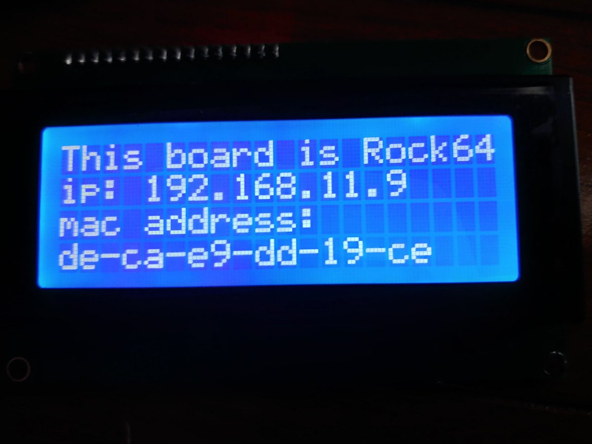
lcd_string("This board is Rock64", LCD_LINE_1)
lcd_string("ip: " + board_ip_addr, LCD_LINE_2)
lcd_string("mac address:", LCD_LINE_3)
lcd_string(board_mac_addr, LCD_LINE_4)
time.sleep(4)
if __name__ == '__main__':
try:
main()
except KeyboardInterrupt:
pass
finally:
LCD_BACKLIGHT = 0x00
lcd_byte(0x01, LCD_CMD)
こんな感じで動きます。
終わりに
ここまで読んでいただいてありがとうございました。
これからI2C制御のLCDで工作をする人の助けになれば幸いです。
この記事は中身がスカスカだったのでそのうちI2C通信について、HD44780 LCDについて、I2Cインターフェースについての記事を分割してあげようかなと思ってます。