Nordic nRF52840 は
Raitac MDBT50Q は 技適として
BLE 5.0(!) と IEEE 802.15.4 で認証を受けています
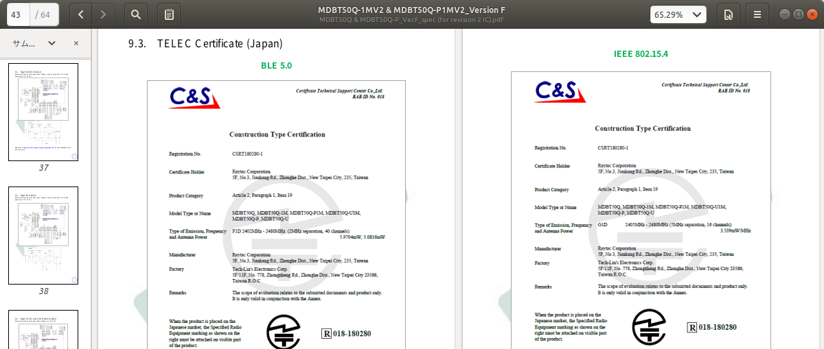
IEEE802.15.4 通信としては ZigbeeやThreadが使えますが、単なる802.15.4のだけの通信を試してみました。
環境
- Raitac MDBT50Q DB
- アオノドン2019
- nRF5_SDK_16.0.0_98a08e2
- Segger Embeddid Studio
- 開発母艦 Ubuntu 18.04
- CP2102 USB シリアルアダプタ
ドキュメント
first
(SDKディレクトリ)/examples/802_15_4/wireless_uart/raw/first/pca10056/blank/ses/wireless_uart_raw_first_pca10056.emProject
を開き、MDBT50Q DBに書き込みます。
second
(SDKディレクトリ)/examples/802_15_4/wireless_uart/raw/second/pca10056/blank/ses/wireless_uart_raw_second_pca10056.emProject
を開き、アオノドン2019に書き込みます。
配線
uart.c において以下のようにハードウェアフローが設定されているので、RTS/CTS線の配線が必要です。
static hal_uart_config_t m_uart_config =
{
    .module         = CONFIG_UART_MODULE,
    .tx_pin         = CONFIG_UART_TX_PIN,
    .rx_pin         = CONFIG_UART_RX_PIN,
    .cts_pin        = CONFIG_UART_CTS_PIN,
    .rts_pin        = CONFIG_UART_RTS_PIN,
    .baudrate       = CONFIG_UART_BAUDRATE,
    .parity         = CONFIG_UART_PARITY,
    .char_size      = HAL_UART_EIGHT_BITS_CHAR,
    .flow_control   = HAL_UART_FLOW_CONTROL_ENABLED,
};
RTS/CTS線を含めて、以下のように配線をします。
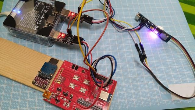
詳細は以下を参照。
「nRF52840 ボードの UART ポートの配線」
https://qiita.com/nanbuwks/items/0a9151f693c346a681cf
実行
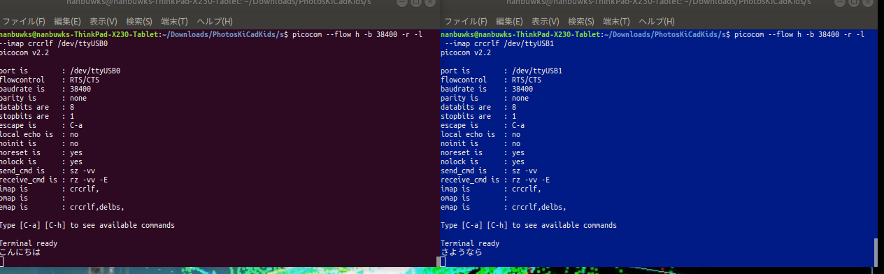
picocomで以下のようにして起動。
First用
picocom --flow h -b 38400 -r -l --imap crcrlf /dev/ttyUSB0
Second用
picocom --flow h -b 38400 -r -l --imap crcrlf /dev/ttyUSB1
picocom の起動パラメータは以下の通り。
- --flow h ハードウェアフロー制御(RTS/CTS線を使う)
- -b 38400 ボーレート 38400bps
- -r 終了時にポートリセットを行わない
- -l 起動時にポートロックしない (排他専有しない)
- --imap crcrlf USBシリアルアダプタから受信した CR コードを CR+LF コードに変換
- /dev/ttyUSB0 または /dev/ttyUSB1 USBシリアルアダプタポート
実行すると、2ターミナル間で通信ができます。
First と Second の違い
両方共、main.c は同じものを使用している。
設定ファイル sdk_config.h でFirstとSecondの違いを作っている。
First側
該当箇所
// <h> Application

//==========================================================
// <o> CONFIG_DEVICE_SHORT_ADDRESS - Device short address
# ifndef CONFIG_DEVICE_SHORT_ADDRESS
# define CONFIG_DEVICE_SHORT_ADDRESS 10
# endif

// <o> CONFIG_OTHER_ADDRESS - Peer device short address
# ifndef CONFIG_OTHER_ADDRESS
# define CONFIG_OTHER_ADDRESS 11
# endif

// </h>
//==========================================================
Second側
該当箇所
// <h> Application

//==========================================================
// <o> CONFIG_DEVICE_SHORT_ADDRESS - Device short address
# ifndef CONFIG_DEVICE_SHORT_ADDRESS
# define CONFIG_DEVICE_SHORT_ADDRESS 11
# endif

// <o> CONFIG_OTHER_ADDRESS - Peer device short address
# ifndef CONFIG_OTHER_ADDRESS
# define CONFIG_OTHER_ADDRESS 10
# endif

// </h>
これらがどこから参照されているかというと、(SDKディレクトリ)/examples/802_15_4/wireless_uart/fsm.c で使用している。
CONFIG_DEVICE_SHORT_ADDRESS
static void a_short_addr_set(void * p_data)
{
    const pib_id_t pib_id =
    {
        .mlme_id = MAC_SHORT_ADDRESS,
    };
    mp_set_req = (mlme_set_req_t *)sys_mm_alloc(sizeof(mlme_set_req_t));
    ASSERT(mp_set_req != NULL);
    mp_set_req->value = (uint8_t *)sys_mm_alloc(mlme_pib_attr_size_calc(pib_id, 0));
    ASSERT(mp_set_req->value != NULL);

    mp_set_req->pib_attribute.mlme_id = MAC_SHORT_ADDRESS;
    uint16_t address = CONFIG_DEVICE_SHORT_ADDRESS;
    memcpy(mp_set_req->value, &address, sizeof(uint16_t));
    mp_set_req->pib_attribute_idx = 0;
    mlme_set_req(mp_set_req, mlme_set_conf);
}
CONFIG_OTHER_ADDRESS
static mcps_data_req_t m_data_req;

・・・

static void a_radio_tx_start(void * p_data)
{
    m_radio_tx_idle = false;

    const hal_uart_descriptor_t * p_descr = uart_descr_get();
    size_t sz = hal_uart_read_buffer_size_get(p_descr);

    LEDS_OFF(BIT(CONFIG_UPSTREAM_PIN));

    if (sz > MAX_MSDU_SIZE)
    {
        sz = MAX_MSDU_SIZE;
    }

    if (sz > 0)
    {
        hal_uart_read(p_descr, &m_radio_tx_buffer[PAYLOAD_START_POSITION], sz);
        memcpy(&m_radio_tx_buffer[COUNTER_POSITION], &tx_sequence_number, MAX_APP_SEQUENCE_NUMBER_SIZE);
# if (CONFIG_SECURE == 1)
        memcpy(m_radio_tx_buffer_shadow, &m_radio_tx_buffer[COUNTER_POSITION],
                                            sz + MAX_APP_SEQUENCE_NUMBER_SIZE);
# endif

        m_data_req.dst_addr_mode = MAC_ADDR_SHORT;
        m_data_req.dst_addr.short_address = CONFIG_OTHER_ADDRESS;
        m_data_req.dst_pan_id = CONFIG_PAN_ID;
        m_data_req.src_addr_mode = MAC_ADDR_SHORT;
        m_data_req.msdu = (uint8_t *)&m_radio_tx_buffer[MAC_MAX_MHR_SIZE];
        m_data_req.msdu_length = sz + MAX_APP_SEQUENCE_NUMBER_SIZE;
        m_data_req.msdu_handle++;
        m_data_req.tx_options.ack = true;
        m_data_req.tx_options.gts = false;
        m_data_req.tx_options.indirect = false;
# if (CONFIG_SECURE == 1)
        m_data_req.security_level = CONFIG_DATA_SECURITY_LEVEL;
        m_data_req.key_id_mode = 0;
# endif
        mcps_data_req(&m_data_req, mcps_data_conf);

        LEDS_ON(BIT(CONFIG_UPSTREAM_PIN));
    }
    else
    {
        m_radio_tx_idle = true;
    }
}
mlme_set_req_t は、(SDKディレクトリ)/components/802_15_4/api/MAC/mac_mlme_pib.h
で定義されている。
/**
 * @brief   MLME-SET.request
 *
 * @details structure for setting a PIB attribute.
 *
 * In accordance with IEEE Std 802.15.4-2006, section 7.1.13.1
 */
typedef struct
{
    /** Do not edit this field. */
    mac_abstract_req_t service;

    /** Confirm to this request. */
    mlme_set_conf_t    confirm;

    pib_id_t           pib_attribute;      /**< PIB Attribute. */
    uint8_t            pib_attribute_idx;  /**< PIB Attribute index. */
    uint8_t          * value;              /**< Attribute value. The value size is calculated
                                                with mlme_pib_attr_size_calc. */
} mlme_set_req_t;
この mlme_set_conf_t は同様に、mac_mlme_pib.h 中で定義されている。
/**
 * @brief   MLME-SET.confirm
 *
 * @details structure for reporting the results of an attempt to write a value
 * to a PIB attribute.
 *
 * In accordance with IEEE Std 802.15.4-2006, section 7.1.13.2
 */
typedef struct
{
    mac_status_t       status;             /**< Status of operation. */
    pib_id_t           pib_attribute;      /**< PIB Attribute. */
    uint8_t            pib_attribute_idx;  /**< PIB Attribute index. */
} mlme_set_conf_t;
ここで指定するパラメータは 802.14.4 MAC層情報ベース管理サービスの MLME-SETによるもの。
このうちの macShortAddress に CONFIG_DEVICE_SHORT_ADDRESS 11 が入る。
また、 CONFIG_OTHER_ADDRESS で使っている mcps_data_req_t は、(SDKディレクトリ)/components/802_15_4/api/MAC/mac_mcps_data.h
で定義されている。
/**
 * @brief   MCPS-DATA.request.
 *
 * @details The MCPS-DATA.request primitive requests the transfer of
 * a data SPDU (i.e., MSDU) from a local SSCS entity to a single peer SSCS entity.
 *
 * In accordance with IEEE Std 802.15.4-2006, section 7.1.1.1.
 */
typedef struct
{
    /** Do not edit this field. */
    mac_abstract_req_t      service;

    /** Confirm to this request. */
    mcps_data_conf_t        confirm;

    /**
     * The source addressing mode for this primitive and
     * subsequent MPDU. This value can take one of the following values:
     * @ref mac_addr_mode_t
     * 0x00 = no address (addressing fields omitted, see 7.2.1.1.8).
     * 0x01 = reserved.
     * 0x02 = 16-bit short address.
     * 0x03 = 64-bit extended address.
     */
    mac_addr_mode_t         src_addr_mode;

    /**
     * The destination addressing mode for this primitive
     * and subsequent MPDU.
     * According to 7.1.1.1.1, Table 41.
     */
    mac_addr_mode_t         dst_addr_mode;

    /** The 16-bit PAN identifier of the entity to which the MSDU is being transferred. */
    uint16_t                dst_pan_id;

    /** The individual device address of the entity to which the MSDU is being transferred. */
    mac_addr_t              dst_addr;

    /** The number of octets contained in the MSDU to be transmitted by
     * the MAC sublayer entity.
     */
    uint8_t                 msdu_length;

    /**
     * The pointer to the set of octets forming the MSDU
     * to be transmitted by the MAC sublayer entity.
     *
     * Caller must provide enough space for MAC and PHY header before this pointer.
     */
    uint8_t               * msdu;

    /** The handle associated with the MSDU to be transmitted by the MAC sublayer entity. */
    uint8_t                 msdu_handle;

    /**
     * The  bits (b0, b1, b2) indicate the transmission options for this MSDU.
     * For b0, 1 = acknowledged transmission, 0 = unacknowledged transmission.
     * For b1, 1 = GTS transmission, 0 = CAP transmission for a beacon-enabled PAN.
     * For b2, 1 = indirect transmission, 0 = direct transmission.
     * For a nonbeacon-enabled PAN, bit b1 should always be set to 0.
     */
    mac_tx_options_t        tx_options;
# if (CONFIG_SECURE == 1)
    uint8_t                 security_level;            /**< Security level. */
    uint8_t                 key_id_mode;               /**< Key ID node. */
    uint64_t                key_source;                /**< Key source. */
    uint8_t                 key_index;                 /**< Key index. */
# endif
} mcps_data_req_t;