・問題文は2次元ですが、3次元FreeCADのマクロで、XY平面上に作図しました。
オリジナル
・YUUU0123 様 (0:00〜6:29)
sympyで(オリジナル 様の方法を参考に)
ver0.10 オリジナル 様より
・△DOA ∽ △BCA
from sympy import *
var('x,BC,t')
eq_soji=Eq(1/BC,x/4)                ;print("#",eq_soji)
BC     =solve(eq_soji,BC)[0]        ;print("#",BC)
eq_sanh=Eq((2*x)**2,4**2+BC**2)     ;print("#",eq_sanh)  # 4次式
# plot(eq_sanh.lhs-eq_sanh.rhs,x)
rep    ={x**2:t}
eq_sanh=eq_sanh.subs(rep)           ;print("#",eq_sanh)
t      =solve(eq_sanh,t)[1]         ;print("#",(pi*t/2).simplify())
# Eq(1/BC, x/4)
# 4/x
# Eq(4*x**2, 16 + 16/x**2)
# Eq(4*t, 16 + 16/t)
# pi*(1 + sqrt(2))
ver0.11 Youtubeコメント 様より
・私は、方べきの定理を勉強中です。
・BE=2,EC=2
from sympy import *
var('x,r',positive=True)
print("#",pi*solve([Eq(r**2+1 ,x**2),Eq(x*(4-x),(r-1)*(r+1))],[x,r])[0][0])
# pi*(1 + sqrt(2))
wolframalphaの1行で。?怪しいグラフがそれぞれでました。
sympyで(余角90°-θの公式)
https://docs.sympy.org/latest/modules/simplify/fu.html#sympy.simplify.fu.TR2
https://docs.sympy.org/latest/modules/simplify/fu.html#sympy.simplify.fu.TR5
https://docs.sympy.org/latest/modules/simplify/fu.html#sympy.simplify.fu.TR6
・初めて「余角」を理解できた気がします。
・点OからADへの垂線の足を点H(2+2=4)。 △HAO∽△HAO x=∠AHO(大きい方)
ver0.21 余角90°-θの公式
# ver0.21 余角90°-θの公式
from sympy import *
from sympy.simplify.fu import TR2,TR5
var('x')
eq1=Eq(2/tan(x)      ,sin(x))         #;print("#",eq1)
eq2=Eq(TR2(eq1.lhs)  ,eq1.rhs)        #;print("#",eq2)
eq3=Eq(eq2.lhs*sin(x),eq2.rhs*sin(x)) #;print("#",eq3)
eq4=Eq(TR5(eq3.lhs)  ,eq3.lhs)        #;print("#",eq4)
cosx=solve(eq4,cos(x))[0]             #;print("#",cosx)
sinx=sqrt(1-cosx**2)                   ;print("#",pi*((2/sinx)**2/2).simplify())
# pi*(1 + sqrt(2))
ver0.22 余角90°-θの公式
# ver0.22 余角90°-θの公式
from sympy import *
from sympy.simplify.fu import TR2,TR6
var('x')
eq1=Eq(2*tan(x)      ,cos(x))          ;print("#",eq1)
eq2=Eq(TR2(eq1.lhs)  ,eq1.rhs)         ;print("#",eq2)
eq3=Eq(eq2.lhs*cos(x),eq2.rhs*cos(x))  ;print("#",eq3)
eq4=Eq(eq3.lhs       ,TR6(eq3.rhs))    ;print("#",eq4)
sinx=solve(eq4,sin(x))[0]              ;print("#",sinx)
cosx=sqrt(1-sinx**2)                   ;print("#",pi*((2/cosx)**2/2).simplify())
# # pi*(1 + sqrt(2))
wolframalphaで。2つ目はうまくいきませんでした。
1つ目
2/tanx=sinx,pi*(2/sinx)**2/2
2つ目
2*tanx=cosx,pi*(2/cosx)**2/2
sympyで(いつもの方法で ???普通はこれ)
ver0.3
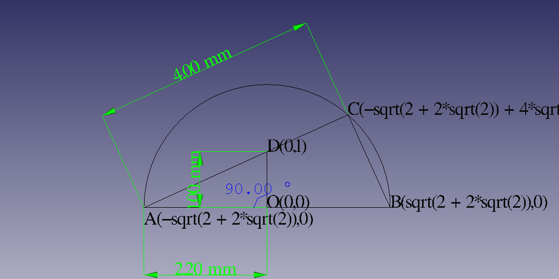
・点Cは、点Aから点Dの方向に4。
OCの長さは半径xと同じ。
# ver0.3
from sympy import *
var('x',positive=True)
O,A,B,D=map(Point,[(0,0),(-x,0),(x,0),(0,1)])
C=A+Point(D-A).unit*4
print("#",pi*(solve(Eq(O.distance(C),x))[0]**2/2))
# pi*(1 + sqrt(2))
FreeCADのマクロで作図
・問題文は2次元ですが、3次元FreeCADのマクロで、XY平面に作図しました。
・計算部分は、Ver.0.3 の コピー貼り付けです。
import FreeCAD
import Part
import DraftTools
import Draft
import Mesh
############################################################################
# ver0.3 点Cは、点Aから点Dの方向に4。OCの長さがx。
from sympy import *
var('x',positive=True)
O,A,B,D=map(Point,[(0,0),(-x,0),(x,0),(0,1)])
C=A+Point(D-A).unit*4
print("#",pi*(solve(Eq(O.distance(C),x))[0]**2/2))
# pi*(1 + sqrt(2))
############################################################################
x_sol=solve(Eq(O.distance(C),x))[0]
rep={x:x_sol}
A=A.subs(rep)
B=B.subs(rep)
C=(C.subs(rep)).simplify()
D=D.subs(rep)
############################################################################
# 3D作図 z=0 XY平面に作図しました。
# 2024-10-08 fontsize 追加しました。従来と互換性がありません。
# 2024-10-20 HR バグ対応済
# 2024-11-2t VL バグ対応済
############################################################################
def myDimension(fontsize,myExtOvershoot,start_point, end_point,HVP):
    x1, y1 = start_point.args
    x2, y2 = end_point.args
    myFlipText = True
    if HVP=="PL":
       myP1  =Point(float(x1),float(y1))
       myP2  =Point(float(x2),float(y2))
       myFlipText = False
       myExtOvershoot1=abs(myExtOvershoot)
    elif HVP=="PR":
       myP1  =Point(float(x1),float(y1))
       myP2  =Point(float(x2),float(y2))
       myFlipText = False
       myExtOvershoot1=-abs(myExtOvershoot)
    elif HVP=="VL":
       # if x1<x2 and y1<y2:
       if x1<=x2 and y1<y2:
          myP1  =Point(float(x1),float(y1))
          myP2  =Point(float(x1),float(y2))
          myExtOvershoot1= abs(myExtOvershoot)
          myFlipText = False
       elif x1<x2 and y1>y2:
          myP1  =Point(float(x1),float(y1))
          myP2  =Point(float(x1),float(y2))
          myExtOvershoot1=-abs(myExtOvershoot)
       elif x1>x2 and y1<y2:
          myP1  =Point(float(x2),float(y1))
          myP2  =Point(float(x2),float(y2))
          myExtOvershoot1= abs(myExtOvershoot)
          myFlipText = False
       else:
          myP1  =Point(float(x2),float(y1))
          myP2  =Point(float(x2),float(y2))
          myExtOvershoot1=-abs(myExtOvershoot)
    elif HVP=="VR":
       if x1<x2 and y1<y2:
          myP1  =Point(float(x2),float(y1))
          myP2  =Point(float(x2),float(y2))
          myExtOvershoot1=-abs(myExtOvershoot)
          myFlipText = False
       elif x1<x2 and y1>y2:
          myP1  =Point(float(x2),float(y1))
          myP2  =Point(float(x2),float(y2))
          myExtOvershoot1= abs(myExtOvershoot)
       elif x1>x2 and y1<y2:
          myP1  =Point(float(x1),float(y1))
          myP2  =Point(float(x1),float(y2))
          myExtOvershoot1=-abs(myExtOvershoot)
       else:
          myP1  =Point(float(x1),float(y1))
          myP2  =Point(float(x1),float(y2))
          myExtOvershoot1= abs(myExtOvershoot)
    elif HVP=="HL":
       if x1 < x2 and y1<y2:
          myP1  =Point(float(x1),float(y2))
          myP2  =Point(float(x2),float(y2))
          myExtOvershoot1= abs(myExtOvershoot)
          myFlipText = False
       elif x1 < x2 and y1>y2:
          myP1  =Point(float(x1),float(y1))
          myP2  =Point(float(x2),float(y1))
          myExtOvershoot1= abs(myExtOvershoot)
          myFlipText = False
       elif x1 > x2 and y1<y2:
          myP1  =Point(float(x1),float(y1))
          myP2  =Point(float(x2),float(y1))
          myExtOvershoot1= abs(myExtOvershoot)
       else:
          myP1  =Point(float(x1),float(y2))
          myP2  =Point(float(x2),float(y2))
          myExtOvershoot1= abs(myExtOvershoot)
    elif HVP=="HR":
       if x1<x2 and y1<=y2:
          myP1  =Point(float(x1),float(y1))
          myP2  =Point(float(x2),float(y1))
          myExtOvershoot1=-abs(myExtOvershoot)
          myFlipText = False
       elif x1<x2 and y1>y2:
          myP1  =Point(float(x1),float(y2))
          myP2  =Point(float(x2),float(y2))
          myExtOvershoot1=-abs(myExtOvershoot)
          myFlipText = False
       elif x1>x2 and y1<y2:
          myP1  =Point(float(x1),float(y2))
          myP2  =Point(float(x2),float(y2))
          myExtOvershoot1=-abs(myExtOvershoot)
       else:
          myP1  =Point(float(x1),float(y1))
          myP2  =Point(float(x2),float(y1))
          myExtOvershoot1=-abs(myExtOvershoot)
    else:
      print("")

    myM   =myP1.midpoint(myP2)
    myT   =myM+myExtOvershoot1*((myP1-myM).unit).rotate( -pi/2 )
    dimension = Draft.makeDimension(
        FreeCAD.Vector(myP1.x, myP1.y, 0),           # 点1の座標
        FreeCAD.Vector(myP2.x, myP2.y, 0),           # 点2の座標
        FreeCAD.Vector(float(myT.x),float(myT.y),0)  # 矢印の位置を中央に設定
    )
    # Ext Overshootを設定
    dimension.ViewObject.ExtOvershoot = -float(myExtOvershoot)

    dimension.ViewObject.FlipText = myFlipText

    # 矢印のスタイルを設定
    dimension.ViewObject.ArrowType    = "Arrow"  # 矢印のタイプを "Arrow" に設定
    dimension.ViewObject.ArrowSize    = fontsize/5
    dimension.ViewObject.TextSpacing  = 0
    dimension.ViewObject.LineColor    = (0.0, 1.0, 0.0)  # 緑色
    dimension.ViewObject.FontSize     = fontsize  # フォントサイズを指定
def myXYZ2Txt_2D(A):
    return ""
def myXYZ2Txt_XY_2D(A):
    return '(' + str(A.x) + ',' + str(A.y) +  ')'
def myTxtXYZ_2D(fontsize,A,myWedgei):
    P5x=float(A.x)
    P5y=float(A.y)
    P5z=0.0
    p5 = FreeCAD.Vector(P5x, P5y, P5z)
    myText = Draft.makeText(myWedgei, p5)
    myText.Label = myWedgei
    FreeCADGui.ActiveDocument.ActiveObject.FontSize = str(fontsize,)+' mm'
    return
def myTxtXYZ_S_2D(fontsize,*xy_tx):
    for i in range(1,int(len(xy_tx)/2)+1):
        myTxtXYZ_2D(fontsize,xy_tx[2*i-2],xy_tx[2*i-1]+myXYZ2Txt_2D(xy_tx[2*i-2]) )
    return
def myTxtXYZ_XY_S_2D(fontsize,*xy_tx):
    for i in range(1,int(len(xy_tx)/2)+1):
        myTxtXYZ_2D(fontsize,xy_tx[2*i-2],xy_tx[2*i-1]+myXYZ2Txt_XY_2D(xy_tx[2*i-2]) )
    return
def myTxtXYZ_MoveY_2D(fontsize,MoveY,A,myWedgei):
    P5x=float(A.x)
    P5y=float(A.y)+MoveY
    P5z=0.0
    p5 = FreeCAD.Vector(P5x, P5y, P5z)
    myText = Draft.makeText(myWedgei, p5)
    myText.Label = myWedgei
    FreeCADGui.ActiveDocument.ActiveObject.FontSize = str(fontsize,)+' mm'
    return
def myTxtXYZ_XY_S_MoveY_2D(fontsize,MoveY,*xy_tx):
    for i in range(1,int(len(xy_tx)/2)+1):
        myTxtXYZ_MoveY_2D(fontsize,MoveY,xy_tx[2*i-2],xy_tx[2*i-1]+myXYZ2Txt_XY_2D(xy_tx[2*i-2]) )
    return
############################################################################
# 3D作図 z=0 XY平面に作図しました。
############################################################################
# 円の作図 FrecCADのdocより
# https://wiki.freecad.org/Macro_Circle
def Freecad3D_circle(x=0.0,y=0.0,z=0.0,radius=0.0,diameter=0.0,circumference=0.0,area=0.0,startangle=0.0,endangle=0.0,arc=0.0,anglecenter=0.0,cord=0.0,arrow=0.0,center=0,placemObject=""):
    from math import sqrt, pi
    if placemObject == "":
        pl = FreeCAD.Placement()
        pl.Rotation = FreeCADGui.ActiveDocument.ActiveView.getCameraOrientation()
        pl.Base = FreeCAD.Vector(x,y,z)
    else:
        pl = FreeCAD.Placement()
        pl = placemObject                                  # placement imposted
    if diameter != 0:                                      # with diameter
        radius = diameter / 2.0
    elif circumference != 0:                               # with circumference
        radius = (circumference / pi) / 2.0
    elif area != 0:                                        # with area
        radius =  sqrt((area / pi))
    elif (cord != 0) and (arrow != 0):                     # with cord and arrow
        radius = ((arrow**2) + (cord**2) / 4.0) / (arrow*2)
    elif (arc != 0) and (anglecenter != 0):                # with arc and anglecenter central in degrees
        radius = ((360/anglecenter)*arc) / pi/2.0
        if endangle != 0:
            startangle  = endangle - anglecenter
        endangle   = anglecenter + startangle
        startangle  = endangle - anglecenter
    if radius != 0:
        try:
            Draft.makeCircle(radius,placement=pl,face=False,startangle=startangle,endangle=endangle,support=None)
            if center != 0:
                x=pl.Base.x
                y=pl.Base.y
                z=pl.Base.z
                Draft.makePoint(x,y,z)
        except Exception:
            App.Console.PrintError("Unexpected keyword argument" + "\n")
        App.ActiveDocument.recompute()
    else:
        App.Console.PrintMessage("Unexpected keyword argument" + "\n")
        App.Console.PrintMessage("circle(x,y,z,radius,diameter,circumference,area,startangle,endangle,[arc,anglecenter],[cord,arrow],center,placemObject)" + "\n")
        App.Console.PrintMessage("circle(radius=10.0,placemObject=App.Placement(App.Vector(11,20,30), App.Rotation(30,40,0), App.Vector(0,0,0)))" + "\n")
    return
def myCircle_2D(myCi):
    x=float(myCi.center.x)
    y=float(myCi.center.y)
    r=float(myCi.radius)
    Freecad3D_circle(
           x=float(x),y=float(y),z=0.0,
           radius=float(abs(r)),
           center=1,
           placemObject=App.Placement(App.Vector(float(x),float(y),0),
           App.Rotation(0,0,0),App.Vector(0,0,0)))
    return
def myCircle_Ogigata_2D(myCi,myStAngle,myEndAngle):
    x=myCi.center.x
    y=myCi.center.y
    r=myCi.radius
    Freecad3D_circle(
           x=float(x),y=float(y),z=0.0,
           radius=float(abs(r)),
           startangle=myStAngle,
           endangle=myEndAngle,
           center=1,
           placemObject=App.Placement(App.Vector(float(x),float(y),0),
           App.Rotation(0,0,0),App.Vector(0,0,0)))
 #  myLine_S_2D(Point(x,y),Point(x+r*cos(rad(myStAngle)), y+r*sin(rad(myStAngle))))
 #  myLine_S_2D(Point(x,y),Point(x+r*cos(rad(myEndAngle)), y+r*sin(rad(myEndAngle))))
    return
def myLine_2D(A,B):
    Ax,Ay,Az=float(A.x),float(A.y),0.0
    Bx,By,Bz=float(B.x),float(B.y),0.0
    pl = FreeCAD.Placement()
    pl.Rotation.Q = (0.4247081540122249, 0.17592004639554645, 0.33985110062924484, 0.8204732460821097)
    pl.Base = FreeCAD.Vector(-3.9166066876399563, -2.1670824762243774, 1.7495260956243028)
    points = [FreeCAD.Vector(Ax,Ay,Az), FreeCAD.Vector(Bx,By,Bz)]
    line = Draft.make_wire(points, placement=pl, closed=False, face=True, support=None)
    Draft.autogroup(line)
    return
def myLine_S_2D(*args):
    for i in range(1,len(args)):
        myLine_2D(args[i-1],args[i])
    return
def myLine_C_2D(*args):
    for i in range(1,len(args)):
        myLine_2D(args[i-1],args[i])
    myLine_2D(args[i],args[0])
    return
def myLine_H_2D(*args):
    for i in range(1,len(args)):
        myLine_2D(args[0],args[i])
    return
##################################################################################
myCircle_Ogigata_2D(Circle(O,x_sol),0,180)
myLine_C_2D     (A,B,C,D)
myLine_S_2D     (O,D)
#
myFontsize =0.3
myMoveY    =myFontsize
myTxtXYZ_XY_S_2D      (myFontsize         ,O,"O",B,"B",C,"C",D,"D")
myTxtXYZ_XY_S_MoveY_2D(myFontsize,-myMoveY,A,"A")
myDimension(myFontsize,myFontsize*6,A,C,"PL")
myDimension(myFontsize,myFontsize*4,A,O,"HR")
myDimension(myFontsize,myFontsize*4,O,D,"VL")
####################################################################################
doc = App.activeDocument()
#App.ActiveDocument.addObject("App::Origin", "Origin")
#App.ActiveDocument.getObject('Origin').Visibility = True
App.ActiveDocument.recompute()
Gui.activeDocument().activeView().viewAxonometric()
Gui.SendMsgToActiveView("ViewFit")
isometric方向?です。(省略)
拡大図
・角度寸法表示はCAD操作です。
寸法線(水平,鉛直,平行)をマクロで作図できるようになりました。
いつものリンク? sympyの実行環境と 参考のおすすめです。
いつもと違うリンクのおすすめです。
対称性・周期性
(再)
sinx=2/tanx,pi*(2/sinx)**2/2
cosy=2*tany,pi*(2/cosy)**2/2