はじめに
$\rm\LaTeX$を使って教材を作成する教師の方々や、レポートを書く物理学徒の皆さんは、電気回路図を描きたいことも少なくないかと思います。
${\rm\TeX}\text{ Live}$には$\text{Ti}\textit{k}\text{Z}$というパッケージが標準でインストールされているので、簡単な図を作成する分には十分ですが、電気回路図となるとなかなか面倒です。もちろん巷には電気回路図を描くフリーソフトが沢山あるので、それを使えば図を挿入することは可能です。しかし、せっかく$\text{Ti}\textit{k}\text{Z}$もインストールされていることなので$\rm\LaTeX$で直接描画したいですよね!?
そこで、$\rm\LaTeX$のパッケージ($\text{Ti}\textit{k}\text{Z}$の拡張)である$\text{CircuiTi}\textit{k}\text{Z}$を使って電気回路図を作成する手順を紹介したいと思います。
(Qiitaの投稿がはじめてなので、至らない部分も多くあるかと思いますがご容赦ください。)
CircuiTikZのインストール
$\text{Ti}\textit{k}\text{Z}$がインストールされていることは前提とします。
まずは下記URLから$\text{CircuiTi}\textit{k}\text{Z}$のZipファイルをダウンロードしてtexmf-localディレクトリ以下に展開し、ターミナルで$ mktexlsrを実行します。
(Unix系であれば管理者権限が必要だそうです。。)
$ mktexlsrにより$\rm\TeX$がパッケージを見つけられるようになります。
Download the contents of CircuiTikZ
回路図作成の基本
$\text{CircuiTi}\textit{k}\text{Z}$がインストールされていることを確認するために試しにエディタで
\documentclass{jsarticle}
\usepackage{amsmath,amssymb}
\usepackage[dvipdfmx]{graphicx}
\usepackage{siunitx}
\usepackage{float}
\usepackage{tikz}
\usepackage{circuitikz}

\begin{document}

\begin{figure}[H]
  \begin{center}
    \begin{circuitikz}[american currents]
 \draw (0,0)
      to[sV=$E$] (0,2)
      to[short] (2,2)
      to[european resistor=$R$] (2,0)
      to[short] (0,0);
      \draw (2,2)
      to[short] (4,2)
      to[L=$L$] (4,0)
      to[short] (2,0);
      \draw (4,2)
      to[short] (6,2)
      to[C=$C$] (6,0)
      to[short] (4,0);
    \end{circuitikz}
    \caption{RLC並列回路}
  \end{center}
\end{figure}
\end{document}
と入力して、コンパイルしてみて下さい。
RLC並列回路が表示されましたでしょうか?
ここでは具体的に回路の書き方を説明しますが、全ては解説できないので詳しい説明はダウンロードした$\text{CircuiTi}\textit{k}\text{Z}$のフォルダ内にあるpdfファイルのマニュアル(英語)を参照してください。($texdoc circuitikzで開けます。)
端子が1つまたは3つの部品
まずは繋げる部分がひとつの部品の書き方です。
\begin{circuitikz}
 (x,y) node[#1,#2](#3){#4};
\end{circuitikz}
$(x,y)$は位置の座標です。#1は部品の名前です(必須)。#2にはオプションを記述します。#3には部品の名前を記述し、後でその部品の位置座標をこの名前で指定します。また#4に書き込んだ文字は図中の部品の接続部分に表示されます。#2,#3,#4は記入しなくてもかまいませんが#4の{ }は$\text{Ti}\textit{k}\text{Z}$の都合上、中身が空でも書くようにしてください。
2端子部品
2端子も似たようなものです。
\begin{circuitikz}
 \draw(x_1,y_1) to[#1,#2] (x_2,y_2);
\end{circuitikz}
$(x_1,y_1)$から$(x_2,y_2)$までをつなげます。#1に部品の名前、#2にオプションを記述してください。#1=hogehogeで図中の部品の上ないし横にhogehogeと表示されます。
オプションでは、i=hogehogeで電流の値、v=hogehogeで端子間の電圧の値をそれぞれ指定すれば図中にそれらを表せます。
例えば
\begin{figure}
\begin{center}
\begin{circuitikz}[european voltages]
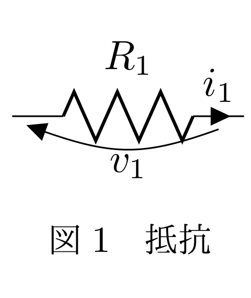
\draw(0,0) to[R=$R_1$,i=$i_1$,v=$v_1$] (2,0);
\end{circuitikz}
\caption{抵抗}
\end{center}
\end{figure}
と入力してコンパイルすると(Rは抵抗です。american resistor(下記参照)と同じ意味です。)

のように表示されます。
Americanな表示とEuropeanな表示
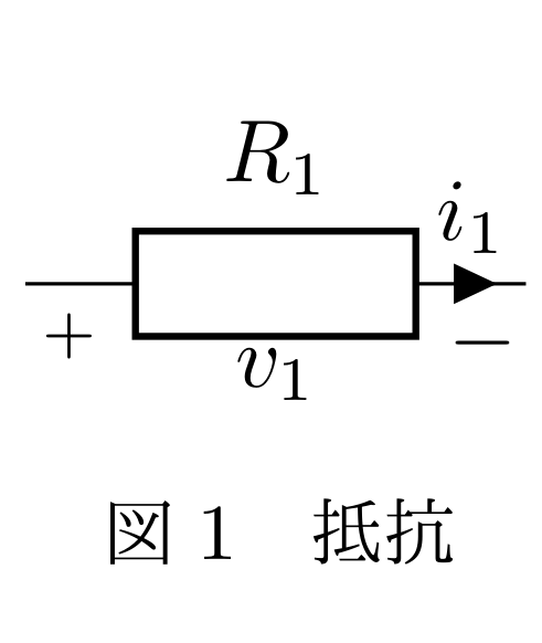
どうやら電気回路の表記は世界で統一されていないらしく、例えば抵抗では、ぎざぎざのものはamerican resistor、四角いものはeuropean resistorで指定します。抵抗の場合はデフォルトでぎざぎざのものになっています。また、電位差を表示する際もamerican voltageとeuropean voltageで違いが出ます。(上記ではeuropean voltageとしています。)
上記の抵抗の図を、american voltages、european resistorで以下のように書き換えると
\begin{figure}
\begin{center}
\begin{circuitikz}[american voltages]
\draw(0,0) to[european resistor=$R_1$,i=$i_1$,v=$v_1$] (2,0);
\end{circuitikz}
\caption{抵抗}
\end{center}
\end{figure}
部品の指定の仕方
こちらのサイトに詳しく載っています。
CircuiTikz package
ここでも少し紹介すると、
導線:short
断線:open
電池:battery
交流電圧源:sV,sinusoidal voltage source
インダクタ(コイル):L,american inductor,cute inductor
コンデンサ:C,capacitor
抵抗:R,american resistor,european resistor
参考Link
$\text{CircuiTi}\textit{k}\text{Z}$が公開されている場所
[circuitikz – Draw electrical networks with TikZ]
(https://www.ctan.org/pkg/circuitikz)
サンプルコード集
Circuitikz examples
