Raycast Padding とは?
Unity2020.1あたりからImageやTextなどのUIオブジェクトに追加された機能です。
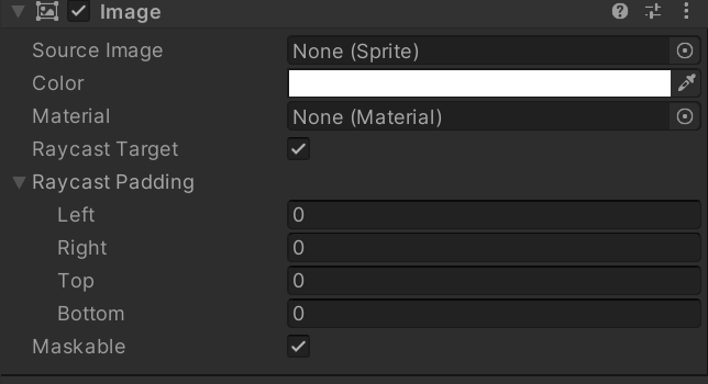
従来は当たり判定の領域 = RectTransformの領域だったところを、RectTransformの値を変えることなく広げたり狭めたりできます。
下図の通り4つのパラメータを設定でき、あくまで矩形を伸縮させるだけで変形はできません。
今までUIオブジェクトよりも大きく当たり判定を取りたいときは、下に少し大きな透明Imageを配置して当たり判定領域を広げたりしていましたが、これが単体でできるようになったという感じです。

GizmoでRaycast Paddingの領域を描画する
Raycast Paddingを実際に使ってみると、数値上でしか変化が見られず、動作させながら調整しないと思い通りの領域にならなかったりする場面があり、そうするとシーンビューでこの領域を視覚化させたいという要望が出てくる...こともある気がします。
ということで、Gizmoの機能を使ってRaycast Paddingの領域を描画してみることにします。
検証環境
Unity2020.3.10f1
実装
今回はImageに対してGizmoを描画していきます。
他のUIコンポーネントタイプも適宜置き換えることで同様に描画可能です。
本記事では、DrawGizmo属性を使用したメソッドを定義していく方針で描画していきます。
[DrawGizmo(GizmoType.Selected)]
private static void DrawImageRaycastPaddingGizmos(Image image, GizmoType gizmoType)
{
}
まず、Imageオブジェクト自体の矩形情報を以下のコードに示すように取得します。
public static Rect GetRect(RectTransform rectTransform)
{
    Vector2 size = rectTransform.rect.size;
    size.x *= rectTransform.lossyScale.x;
    size.y *= rectTransform.lossyScale.y;

    return  new Rect
    {
        center = (Vector2) rectTransform.position - new Vector2(
            rectTransform.pivot.x * size.x,
            rectTransform.pivot.y * size.y
        ),
        size = size,
    };
}
このメソッドで取得したRectに、Image.raycastPaddingの値を加算したものを描画します。
Image.raycastPaddingはVector4のパラメータで、xからwがそれぞれ、Left, Bottom, Right, Topの値を表しています。
また、描画には、Gizmo.DrawLine を使用します。
これらを踏まえると以下のようなコードになります。
[DrawGizmo(GizmoType.Selected)]
private static void DrawImageRaycastPaddingGizmos(Image image, GizmoType gizmoType)
{
    var color = Color.red; // 色は適当に
    Gizmos.color = color;

    var positions = new Vector3[4];
    var rect = GetRect(image.rectTransform);
    var pad = image.raycastPadding;
    positions[0] = new Vector3(rect.x + pad.x, rect.y + pad.y);
    positions[1] = new Vector3(rect.x + rect.width - pad.z, rect.y + pad.y);
    positions[2] = new Vector3(rect.x + rect.width - pad.z, rect.y + rect.height - pad.w);
    positions[3] = new Vector3(rect.x + pad.x, rect.y + rect.height - pad.w);

    Gizmos.DrawLine(positions[0], positions[1]);
    Gizmos.DrawLine(positions[1], positions[2]);
    Gizmos.DrawLine(positions[2], positions[3]);
    Gizmos.DrawLine(positions[3], positions[0]);
}
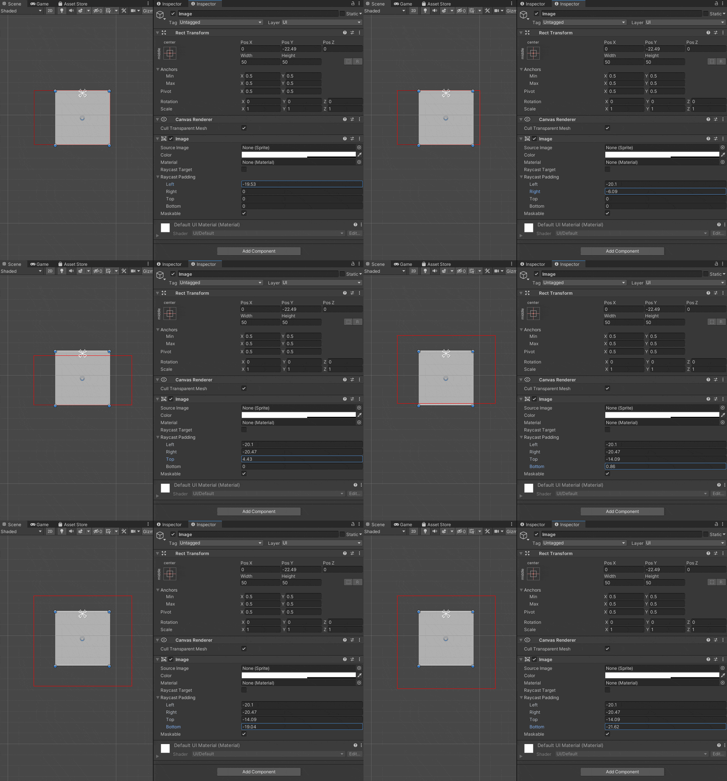
Raycast Paddingは、正の値を設定すると矩形の内側に進み、負の値を設定すると矩形の外側に広がることに注意して適宜加算と減算をしています。(↓の図を見ると分かりやすいです)
これでImageオブジェクトを作成し、シーンビューで選択すると下図のようにRaycast Paddingのサイズに合わせて赤い枠を描画することができることが確認できると思います。
RectTransformのScaleを考慮する
少し不思議な挙動な気もしますが、Raycast Paddingは、RectTransformのScaleの影響を受けます。
つまり、例えば Scaleを2倍にするとRaycast Paddingの値も設定した数値の2倍に広がるということです。
Paddingの各数値自体は変わっておらず、一見Scaleに依存しない値に見えるので注意が必要です。
Scaleを考慮したコードが以下になります。
...
var scale = image.rectTransform.localScale;
var positions = new Vector3[4];
var rect = GetRect(image.rectTransform);
var pad = image.raycastPadding;
positions[0] = new Vector3(rect.x + pad.x * scale.x, rect.y + pad.y * scale.y);
positions[1] = new Vector3(rect.x + rect.width - pad.z * scale.x, rect.y + pad.y * scale.y);
positions[2] = new Vector3(rect.x + rect.width - pad.z * scale.x, rect.y + rect.height - pad.w * scale.y);
positions[3] = new Vector3(rect.x + pad.x * scale.x, rect.y + rect.height - pad.w * scale.y);
...
Raycast TargetがOnのときだけ描画する
Raycast Targetでないオブジェクトは描画しなくても良いから消したいという場合があるかもしれません。
これは単純な話で、ImageクラスのRaycast Targetパラメータを読み取るだけでできます。
if (image.raycastTarget)
{
   // Gizmos.Draw...
}
おわりに
以上を踏まえたソースコード全体は以下のようになります。
ソースコード全体
using UnityEditor;
using UnityEngine;
using UnityEngine.UI;

public class RaycastPaddingEditor
{
    [DrawGizmo(GizmoType.Selected)]
    private static void DrawImageRaycastPaddingGizmos(Image image, GizmoType gizmoType)
    {
        var color = Color.red;

        Gizmos.color = color;

        var rt = image.rectTransform;
        var positions = new Vector3[4];
        var rect = GetRect(image.rectTransform);
        var pad = image.raycastPadding;
        positions[0] = new Vector3(rect.x + pad.x, rect.y + pad.y);
        positions[1] = new Vector3(rect.x + rect.width - pad.z, rect.y + pad.y);
        positions[2] = new Vector3(rect.x + rect.width - pad.z, rect.y + rect.height - pad.w);
        positions[3] = new Vector3(rect.x + pad.x, rect.y + rect.height - pad.w);

        for(int i = 0; i < positions.Length; i++)
        {
            Debug.Log($"name= {image.gameObject.name} : {positions[i]}");
        }

        if (image.raycastTarget)
        {
            Gizmos.DrawLine(positions[0], positions[1]);
            Gizmos.DrawLine(positions[1], positions[2]);
            Gizmos.DrawLine(positions[2], positions[3]);
            Gizmos.DrawLine(positions[3], positions[0]);
        }
    }

    public static Rect GetRect(RectTransform rectTransform)
    {
        Vector2 size = rectTransform.rect.size;
        size.x *= rectTransform.lossyScale.x;
        size.y *= rectTransform.lossyScale.y;

        return  new Rect
        {
            center = (Vector2) rectTransform.position - new Vector2(
                rectTransform.pivot.x * size.x,
                rectTransform.pivot.y * size.y
            ),
            size = size,
        };
    }
}
しかし実はこれだけだとまだ考慮が足りておらず、RectTransformのRotationに応じて回転させないと、実際の挙動と描画領域に差異が出てしまいます。
UIを回転して使用する場合は回転処理を加えたうえで利用してください。
今回は省略してしまいましたが、余裕があるときに追記したいと思います。
