日本語は英語の下にあります (Japanese follows English)
Introduction
The goal of this article is to provide typical service insertion design options and considerations in data center network using traditional network and Cisco ACI(Application Centric Infrastructure)
This article is for Day 17th of Cisco Systems Japan Advent Calendar 2019 provided by volunteers in Cisco Japan though I'm not Cisco Japan employee anymore. I'm Minako, Technical Marketing Engineer at Cisco Data Center Business Group in San Jose. I'm going to write this article in Japanese and English so that Non-Japanese speaker can also read it. (My Japanese and English sentences are not something translated each other. I'm just writing my thought in both languages)
2017: https://qiita.com/advent-calendar/2017/cisco
2018: https://qiita.com/advent-calendar/2018/cisco
2019: https://qiita.com/advent-calendar/2019/cisco
Service Chaining (Service Insertion)
What do you imagine when you hear "Service Chaining/Service Insertion"? Most of folks would imagine a way or a solution to insert L4-L7 Service device such as Firewall and Load Balancer to traffic paths. This article uses the word "Service Chaining/Service Insertion" in that sense.
Typical design options for firewall insertion
The followings are typical design options in traditional network.
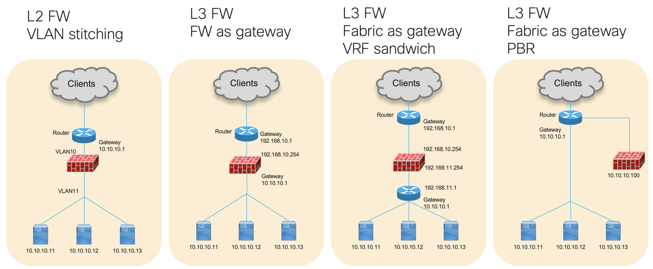
Option 1: L2 firewall between servers and the gateway of servers
It's typically called VLAN stitching. Inter-VLAN traffic goes through an L2 firewall because it's required to reach the gateway or another BD.
Option 2: L3 Firewall is the gateway of servers
Inter-subnet traffic goes through an L3 firewall because going through the firewall that is the gateway is required to reach another subnet.
Option 3: Router/L3 switch is the gateway of servers (VRF sandwich)
It's typically called VRF stitching/sandwich. Front and back end routers in the picture are different routers/VRFs and a firewall is in between. Inter-router/VRF traffic goes through the firewall.
It's been recommended in CVD(Cisco Validated Design) since Catalyst6500 and Nexus7000 days because unlike option 2, all of inter-subnet traffic needs to go through a firewall, inter-subnet traffic is handled by the fabric (router or L3 switch) that has higher performance than the firewall.
Option 4: Router/L3 switch is the gateway of servers (PBR)
Unlike Option 3, multiple routers/VRFs is not required but use of PBR(Policy Based Routing) is required to make traffic go through the firewall.
Typical challenges
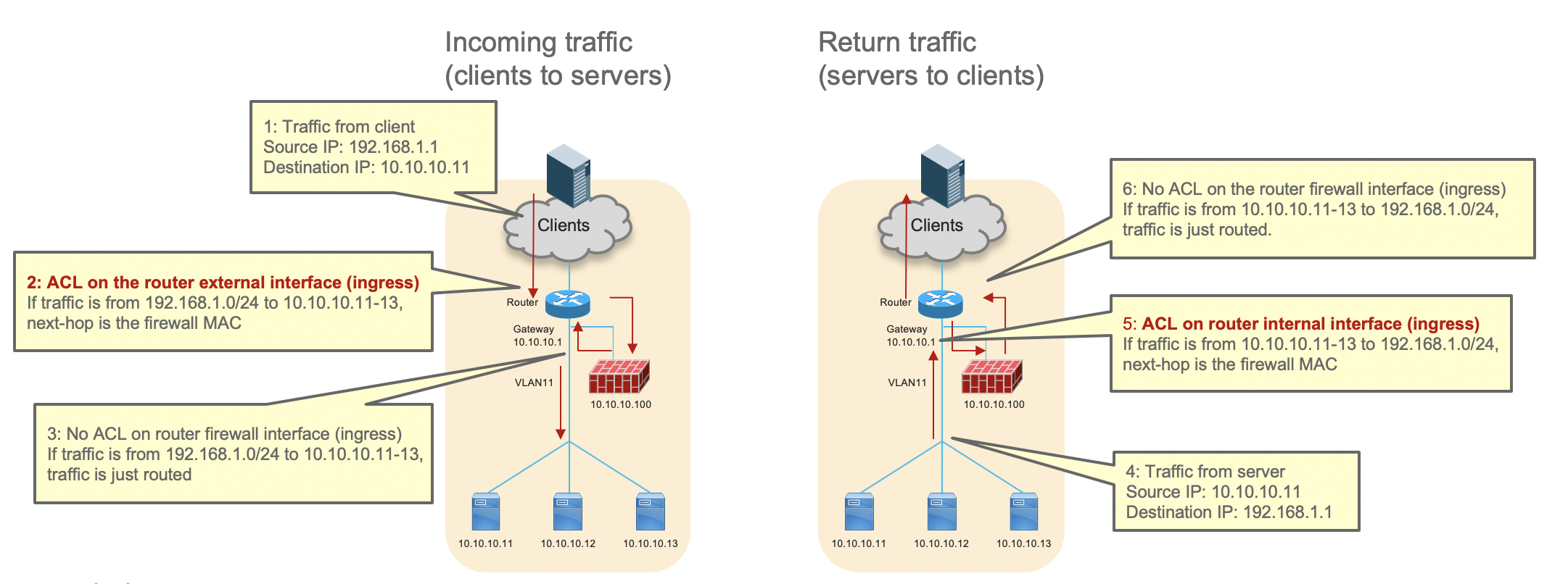
Though option 1 and 2 are simple, firewall could be a bottleneck if there are huge amount of traffics because all of inter-subnet traffic needs to go through the firewall. Option 3 and 4 address this challenge by using distributed L3 gateway functionality instead of routing on single point, the configuration gets complicated because option 3 requires multiple VRFs and routing, and option 4 requires PBR. Especially ACL(Access Control List) for PBR could be even more complicated if there are many network devices. The following is an example, which has firewall insertion using PBR with one router.
By using ACL to catch traffic from external to specific internal destination, PBR is enabled on the ingress direction of the router's external interface to set the firewall as next-hop for the specific traffic.
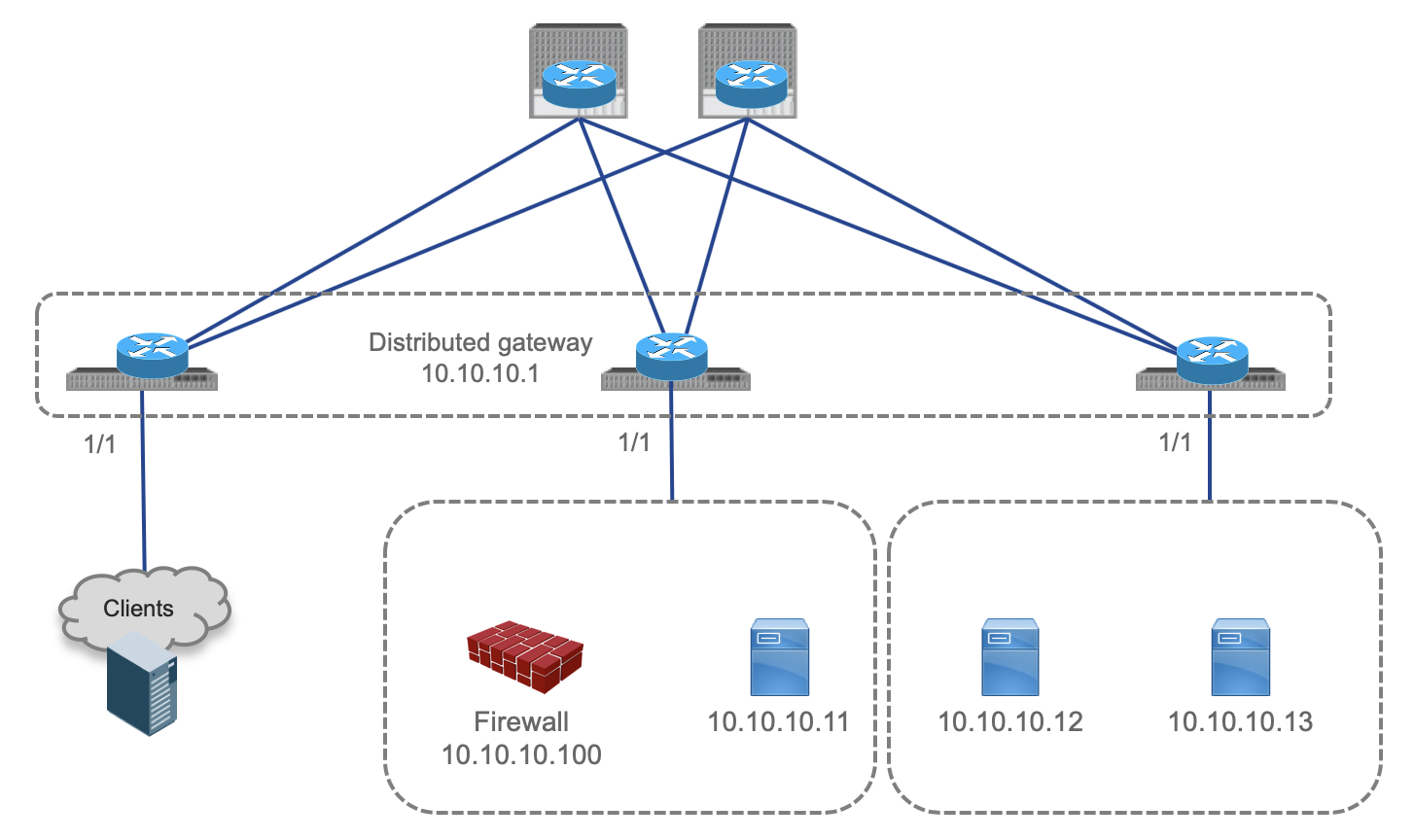
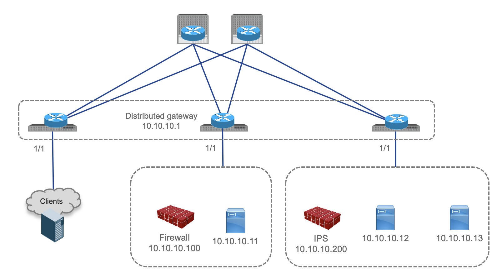
It's not that complicated, is it? What if there are multiple routers, and a firewall and servers are connected to the same interface because of virtualization? Please think about it a bit by using the following image.
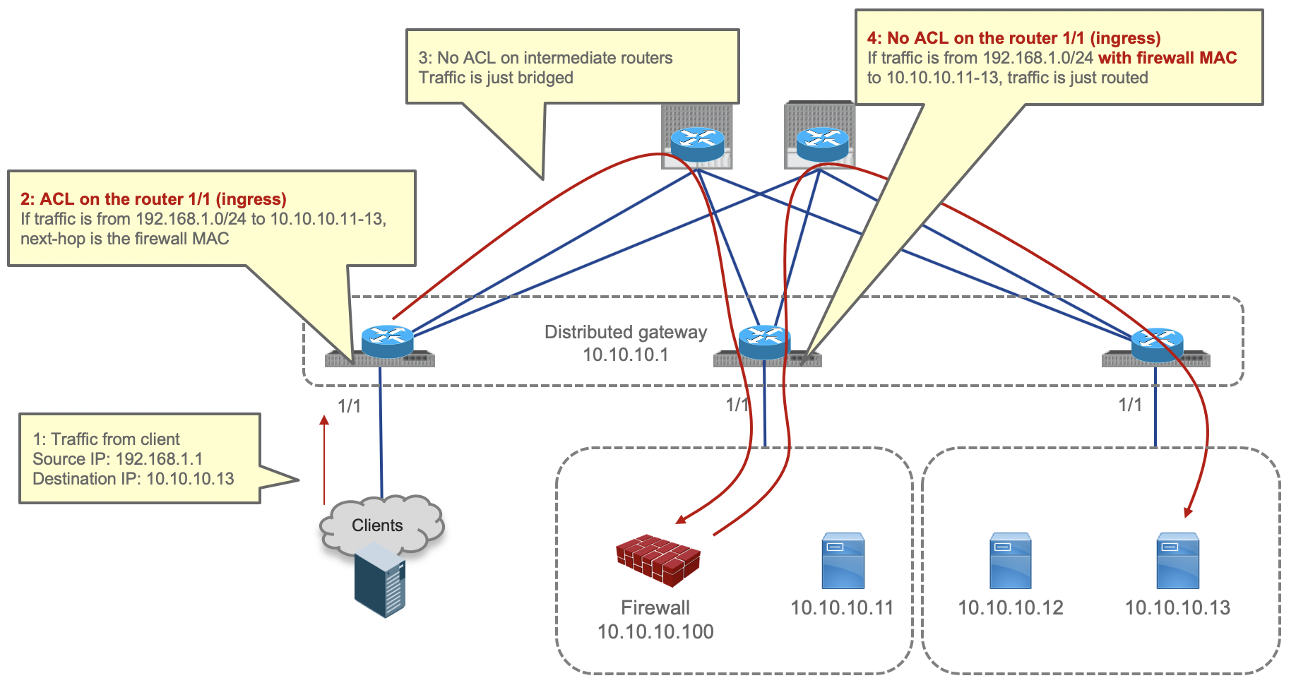
This would be like the following. Please pay attention at the fact that configuration on multiple routers is required, and number 2, 4, 6 and 8 in the image. Firewall MAC address must be in the ACL criteria to identify if firewall has been inserted or not.

What if service chaining: concatenating multiple service devices, is required? For example, TCP optimizer or IPS is inserted followed by firewall. Please think about it a bit by using the following image.
This would be like the following. It's easy to imagine that it could be even more complicated in case of typical design today: distributed gateways and virtual machines. Whether traffic should be forwarded or setting a service device as the next-hop, and where the traffic comes from should be taken into the consideration. (This example is the simplest example that omits couple of stuffs. For example, if VXLAN is used between the routers, and firewall and IPS are in different VLANs, VXLAN ID is changed by the routers during VXLAN encap/decap. In that case, where ACL is applied might be different. This example and flow is not intended to show configuration example or promise the possibility of the design using particular vendors. It's just an example to explain general consideration)


How Cisco ACI tackles it
Overview
This section covers Cisco ACI brief overview. Please see other ACI documents for details.
The Cisco ACI fabric includes Cisco Nexus 9000 Series switches with the APIC to run in the leaf/spine ACI fabric mode (Starting from APIC version 4.1, 3-tier design is supported). Leaf nodes have common distributed gateway IP. Subnets are distributed within the fabric by using VXLAN. Not only physical server but also VM and container can be connected to the fabric regardless hypervisor type.
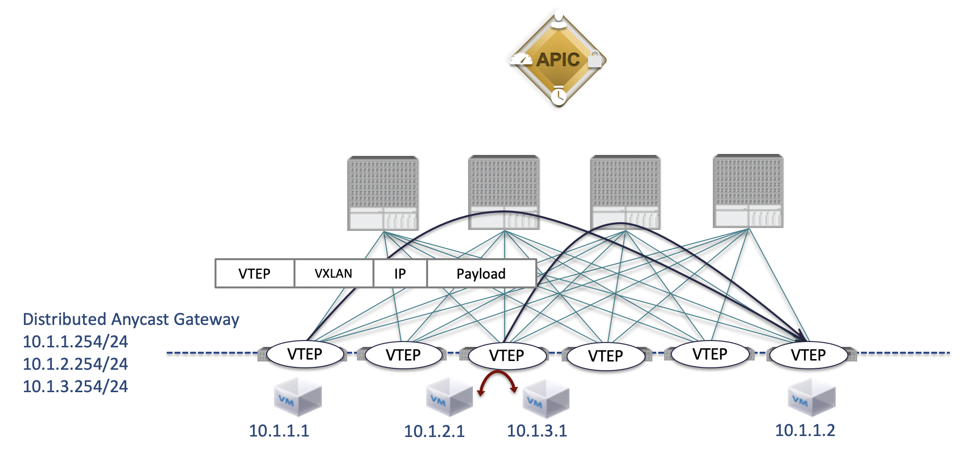
However, users don’t need to be conscious of VXLAN configuration or overlay/underlay design in fabric. For example, VTEP IP is automatically assigned by APIC and required permit/deny security rules are applied without paying attention on ingress/egress direction. What we as users need to do is to define policy. The group is called EPG(End Point Group), and traffic handling requirement between EPGs or within EPG is called Contract. The important thing is that various attributes can be used ad EPG classification criteria. Not only VLAN and port, but also IP/MAC and VM information can be used. In addition to permit action, redirect and copy traffic are options for a contract.

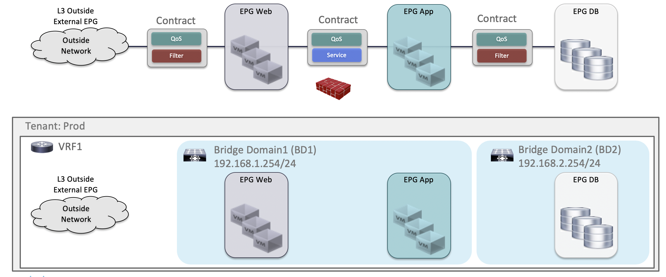
For example, specific traffic can be redirected to the firewall even between Web EPG and App EPG that are in same subnet as shown in the following image. The users don't need to pay attention on ingress/egress traffic direction for ACL on all of the related switches. (That said, redirect destination information such as firewall needs to be configured in APIC)
Forwarding behavior
Forwarding behavior is similar to the previous example. However the important thing is that we as the users don't have to be conscious of detailed forwarding path and configuration on each switch, thanks to Policy enforcement (permit, deny, redirect and copy) using EPG information and the information whether policy has been enforced or not. Because the first traffic is Web to App but the traffic came back from the firewall is Firewall to App, different policy is applied without MAC based ACL even though source and destination IP are exactly same. In addition that, the information whether policy has been enforced or not is carried in VXLAN packet so that there is no risk to redirect traffic more than once.

The important thing is that this can be done using our intent without detailed traffic flow and configuration and this design can be scaled easily, for example: adding switch nodes, service chaining such as concatenating firewall-IPS-TCP optimizer, adding service devices and expanding it to multi location data centers. These are pretty important in actual data center design, aren't they? In case of ACI, individual switch configuration is not needed and service chaining using multiple service devices can be done by defining the order of service devices. Please see ACI PBR white paper for details.
I will write another article on 12/22, which is regarding multi location data center and how to add service devices easily by keeping incoming and return traffic going to same service device.
Summary
This article covers typical design consideration for service insertion in data center network. I'm going to write the continuation: about design considerations for multi-location data center, in the article for Day 22nd.
Useful Links
https://www.cisco.com/c/en/us/solutions/data-center-virtualization/application-centric-infrastructure/white-paper-listing.html
https://www.cisco.com/c/dam/en/us/td/docs/switches/datacenter/aci/apic/sw/4-x/troubleshooting/Cisco_TroubleshootingApplicationCentricInfrastructureSecondEdition.pdf
https://www.ciscolive.com/global/on-demand-library.html
Disclaimer
Opinions expressed here are my personal opinions.
はじめに
この記事は典型的なデータセンターネットワークにおける典型的なサービスインサーションデザイン例を、既存のネットワークとCisco ACI(Application Centric Infrastructure)を使って説明します。
この記事はシスコの有志による Cisco Systems Japan Advent Calendar 2019 の 17 日目として投稿しています。
2017年版: https://qiita.com/advent-calendar/2017/cisco
2018年版: https://qiita.com/advent-calendar/2018/cisco
2019年版: https://qiita.com/advent-calendar/2019/cisco
私はCisco Systems, Inc で Data Center Switch関連のTechnical Marketing Engineerをやっています。非日本語話者の方にも目を通していただけるように日本語と英語で書こうと思います。(英語は日本語の文章をそのまま翻訳したものではありません)
Service Chaining (Service Insertion)
サービスチェイニング/サービスインサーションを聞いたら何を想像されるでしょうか。おそらく多くの人は、どうやってFirewall, Load BalancerといったいわゆるL4-L7サービスデバイスと呼ばれる物をどうやってトラフィックの通り道に入れるか、その手法やソリューションを想像されるのではないでしょうか。この記事においても、その意味で使っていきます。
典型的なFirewallデザイン例
既存のネットワークでの典型的なFirewallのデザイン例をいくつか以下に示します。
オプション1: サーバーとサーバーのゲートウェイの間にL2 Firewallを配置。
VLAN stitchingと呼ばれる方法です。ゲートウェイに向かうためにはFirewallを通らざるを得ないため、VLANまたぎのトラフィックがFirewallを経由します。
オプション2: サーバーのゲートウェイがL3 Firewall
異なるサブネットに向かうためにはゲートウェイであるFirewallを通らざるを得ないため、サブネットまたぎのトラフィックがFirewallを経由します。
オプション3: サーバーのゲートウェイがルーターまたはL3スイッチ (VRF sandwich)
フロントエンドのルーターとバックエンドのルータは、異なるルーター/VRFで、その間にFirewallが配置されています。ルーター/VRF間のトラフィックがFirewallを経由します。
Catalyst6500, Nexus7000の頃からCVD(Cisco Validated Design)ではこの方法が推奨されてきました。なぜなら全てのサブネットまたぎのトラフィックがFirewallを経由するオプション2と異なり、サブネットまたぎの通信はFirewallよりもハイパフォーマンスなファブリック(ルーターまたはL3スイッチ)で処理できるからです。
オプション4: サーバーのゲートウェイがルーターまたはL3スイッチ (PBR)
オプション3と異なり複数のルータ/VRFは必要ありませんが、トラフィックをFirewall経由にするためPBR(Policy Based Routing)をゲートウェイとなるデバイスに設定する必要があります。
典型的なこまりごと (Typical challenges)
オプション1, 2は全てのサブネットまたぎのトラフィックはFirewallを通過せざるを得ないため、トラフィック量が多い場合Firewallがボトルネックになりがちです。オプション3と4はその心配はありませんが、オプション3は複数のVRFとルーティング、オプション4はPBRの設定を管理する必要があるため設定が複雑になりがちです。特にネットワーク機器が複数台ありPBRの場合はACL(Access Control List)の設定が以下のように複雑になります。以下に最もシンプルなルータ一台でのPBRを用いたfirewall接続の例を示します。
外から来た特定の宛先向けのトラフィックをひっかけるACLを使って、そのトラフィックのみnext-hopをfirewallにするようなPBRをルーターのexternal interfaceのingressに設定します。同様に逆方向のトラフィックに関しても同様にルーターのinternal interfaceのingressの設定します。
これなら問題なくできそうですが、ルーターが複数台ありfirewallとserverが仮想化されて同一のインターフェースに接続されている場合はどうでしょうか?以下の図で少し考えてみてください。
こんな感じです。複数のルータへの設定が必要なこと、そして2,4,6,8に注目してください。firewallが挿入された後かどうかを判別するためにfirewallのMACアドレスもACLの条件とする必要があります。
さて、サービスデバイスをチェイニングさせたい、つまり複数台ある場合はどうでしょうか?例えば、Firewallの後にTCP最適化装置やIPSを入れたい場合です。以下の図で少し考えてみてください。
こんな感じです。最近の典型的なデザイン: 分散された仮想マシンとゲートウェイのデザインの場合複雑になることが容易に想像できるのではないでしょうか。トラフィックをそのままフォワードするべきかサービスデバイスをネクストホップにするか、それがどの方向から来るかを意識した設定が必要です。(これは最もシンプルな例で色々なことを省略しています。例えばVXLANがルータ間で使用されていて、FirewallとIPSが異なるVLANにいる場合VXLANの処理とともにVXLAN IDが変わるでしょう。その場合ACLを適用する箇所も変わるかもしれません。この図は特定のベンダーでの実現可能性と設定例を示したものではありません。あくまでイメージ用です)
Cisco ACIでのアプローチ
Overview
以下に簡単にCisco ACIの紹介をします。Cisco ACIの詳細についてはここでは割愛しています。各種ドキュメントをご残照ください。
Nexus9000 スイッチとコントローラーであるAPICで構成されるデータセンターネットワーク製品です。Spine-Leaf型の 2 tier トポロジーで(3 tierも可能です)各Leafが共通のゲートウェイIPを持ち、サブネットはファブリック内で延伸され、スイッチ間はVXLANを使用します。つながるエンドポイントは物理サーバでもVMでもコンテナでも大丈夫です。
しかしファブリック内のoverlay, underlayの構成やVXLANの設定を意識する必要は全くありません。VTEPのIPは自動的にAPICから割り振られますし、必要なセキュリティのpermit/denyルールはingress/egressを意識する必要なく適用されます。我々がやるのは、ポリシー(通信要件)の定義のみです。そのポリシーの定義はグルーピング(誰がどのグループなのか)と、グループ間/内でどの通信を許可するかの定義です。そのグループのことをEPG(End Point Group)と言い、EPG間/内の通信要件をコントラクト(Contract) と言います。重要なことは、EPGのグルーピングの条件が多様なことです。これまでのようなVLANやポートだけでなくIP/MACやVMの情報を使うことができます。また、このContractは通信をpermitするだけではなくredirectさせたりcopyさせることができます。
例えば、この図のようにWeb EPG とApp EPGは同じサブネットにいるけれども特定のトラフィックをfirewallにredirectすることが可能です。先ほどの例のようにIPアドレスとMACアドレスとingress/egressを意識しながらACLをすべての関連するスイッチに書く必要はありません。(Redirect先であるfirewallの情報はAPICに設定する必要があります)
実際のトラフィックの流れ
実際のトラフィックの流れは先ほどに似ていますが、我々がトラフィックの流れと詳細な設定を意識することがないという点が異なります。それを実現しているのがEPGの情報を用いてのポリシー適用(permit, deny, redirect)とポリシーが適用された後かどうかの情報です。最初のトラフィックは Web -> App ですが、 Firewallから戻ってきたトラフィックは、Firewall -> Appのため、IPが全く同じでもMACベースのACLを意識することなく異なるポリシーを適用することができます。また、すでにポリシーが適用されたかどうかがわかるため、二重にredirectをすることもありません。
重要なのは我々がトラフィックの流れと詳細な設定を意識することなく実現可能なこと、また容易なスケールアウトが可能なことです。ここでいうスケールアウトとは、スイッチの台数変更、複数台のサービスチェイニング(例えばFirewall-IPS-TCP optimizer)、サービスデバイス数の追加、複数ロケーションのデータセンターへの拡張です。実際のデータセンターデザインでは重要なことではないでしょうか。ACIの場合個別のスイッチに設定をする必要がありませんし、複数台のデバイスの挿入はContractにどの順番でサービスデバイスを挿入すればいいかを定義するのみです。詳細はACI PBR white paperを参照ください。
https://www.cisco.com/c/en/us/solutions/data-center-virtualization/application-centric-infrastructure/white-paper-c11-739971.html
サービスデバイス数の追加と複数ロケーションのデータセンターにおいてどうやってトラフィックを同じサービスデバイスにredirectするかについては次回12/22に書きます。
まとめ
典型的なデータセンターネットワークにおけるサービスインサーションデザイン例を説明しました。続きはこれがマルチロケーションのデータセンターになった場合の話を12/22に書きます。
参考になるURL
https://www.cisco.com/c/en/us/solutions/data-center-virtualization/application-centric-infrastructure/white-paper-listing.html
https://www.cisco.com/c/dam/en/us/td/docs/switches/datacenter/aci/apic/sw/4-x/troubleshooting/Cisco_TroubleshootingApplicationCentricInfrastructureSecondEdition.pdf
https://www.ciscolive.com/global/on-demand-library.html
免責事項
本サイトおよび対応するコメントにおいて表明される意見は、投稿者本人の個人的意見であり、シスコの意見ではありません。本サイトの内容は、情報の提供のみを目的として掲載されており、シスコや他の関係者による推奨や表明を目的としたものではありません。各利用者は、本Webサイトへの掲載により、投稿、リンクその他の方法でアップロードした全ての情報の内容に対して全責任を負い、本Web サイトの利用に関するあらゆる責任からシスコを免責することに同意したものとします。