日本語は英語の下にあります (Japanese follows English)
Introduction
Let's continue from Day 17th. If you've not read the article of Day 17th 2019, I would recommend to check Day 17th first before you read this article.
2017: https://qiita.com/advent-calendar/2017/cisco
2018: https://qiita.com/advent-calendar/2018/cisco
2019: https://qiita.com/advent-calendar/2019/cisco
The goal of this article is to provide service insertion design considerations in multi location data centers and how to add service devices easily using Cisco ACI(Application Centric Infrastructure).
How to add service devices easily for scale
Previous article discussed PBR based on the assumption that the PBR destination is a single service device. However, PBR can load-balance traffic to more than just one PBR destination such as an individual firewalls. If, for example, you have three PBR destinations, IP and MAC address pairs are configured in a PBR policy, and traffic is redirected to one of the three PBR nodes based on hashing. The hash tuple is the source IP address, destination IP address, and protocol type by default. Because L4-L7 devices perform connection tracking, they must see both directions of a flow. Therefore, you need to make sure that incoming and return traffic are redirected to the same PBR node. Symmetric PBR is the feature that enables this capability.


Symmetric PBR is useful for inserting multiple service nodes to scale a system. If, for example, you are going to deploy new system but you are not sure how much growth your system is going to see, you would probably choose small firewall and would replace it with bigger one when needed. By using symmetric PBR, you can simply add additional service nodes and ACI fabric will take care of load-balancing to those service nodes, keeping incoming and return traffic going to the same service node.
Multi location datacenter design consideration
The critical requirement for integrating stateful service nodes with multi location data centers is that you must avoid creating an asymmetric traffic path for the incoming and return directions of traffic flow, because doing so would cause communication drops due to the stateful nature of service nodes such as a firewall (when state information cannot be replicated across independent pairs of service nodes). Figure below illustrates an example. Please forget about ACI for a while. This consideration is not specific to ACI but general design consideration. For incoming traffic from an external client to an internal endpoint in site 2, traffic may be steered toward site 1 depending on the routing metric. However, the outbound traffic from the internal endpoint goes out through the local external connectivity in site 2. The return traffic would hence be dropped by the external firewall connected to site 2 since the firewall doesn’t have the connection state information for the traffic flow that was created earlier on the external firewall connected to site 1.
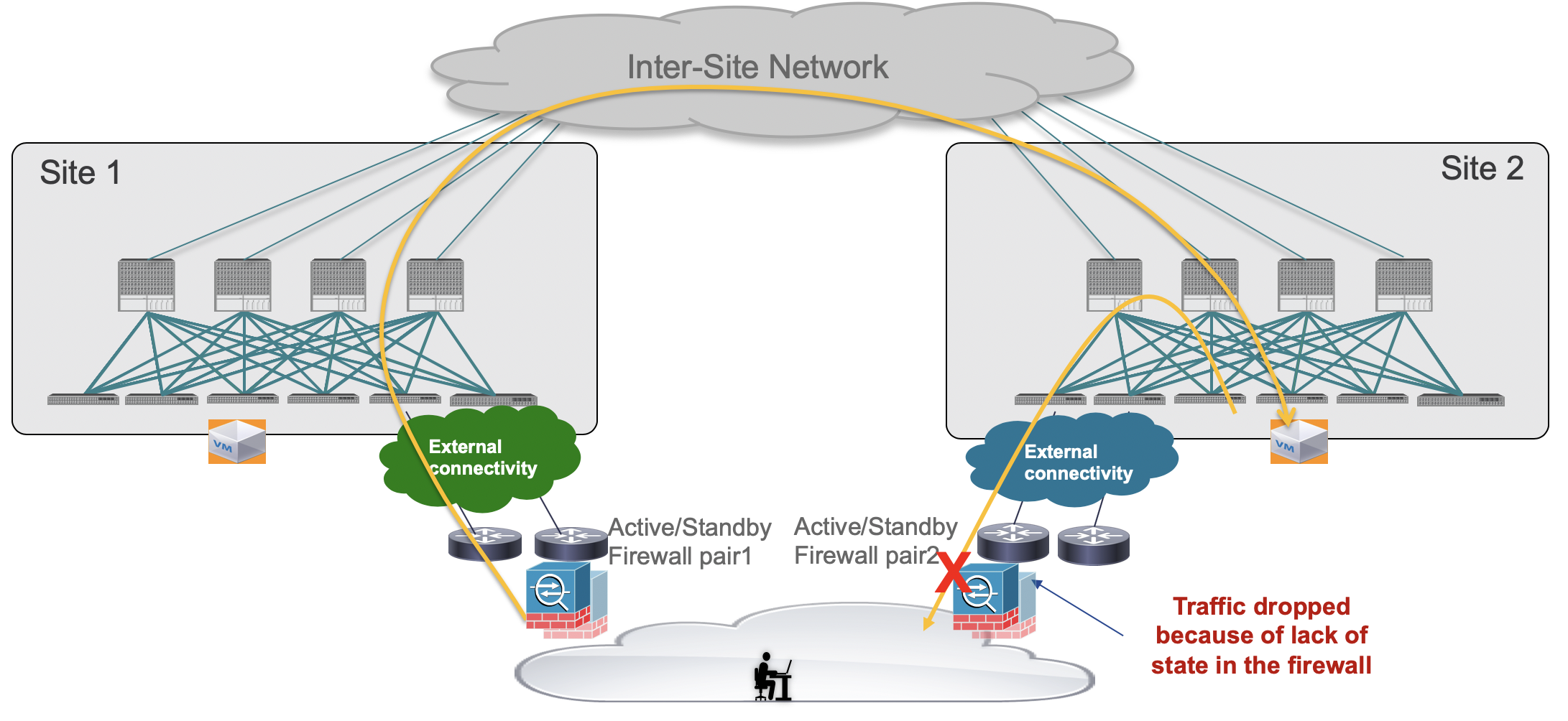
A solution is therefore required to keep both directions of traffic flowing through the same service node. The asymmetric traffic path shown in the previous figure for traffic destined to endpoints that are part of the subnet stretched across sites, can be avoided by leveraging host-route advertisement to optimize the traffic path for ingress communication, but this approach to avoid asymmetricity can be used for a north-south traffic path only.
Then, what sort of options would be available for multi location data centers? Let's take a look at what options are available in ACI Multi-pod and Multi-site.
Cisco ACI Multi-pod design options
For more information on Cisco ACI Multi-pod, please refer to the white paper below:
https://www.cisco.com/c/en/us/solutions/collateral/data-center-virtualization/application-centric-infrastructure/white-paper-c11-737855.html
For more information on Cisco ACI Multi-pod and L4-L7 service integration, please refer to the white paper below:
https://www.cisco.com/c/en/us/solutions/collateral/data-center-virtualization/application-centric-infrastructure/white-paper-c11-739571.html
The figure below illustrates three deployments for integrating service nodes with Cisco ACI Multi-Pod fabrics. The recommendations are option 1 and 2. Though firewall is used in the figure, it's applicable to other service nodes such as IPS and TCP optimizer.
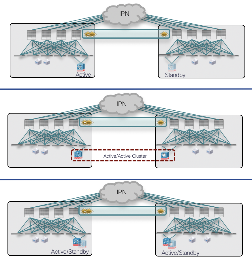
Option 1: Active-Standby service node cluster stretched across locations.
This model does not create an asymmetric traffic path because traffic always go to the active service node. At the same time, because of the existence of a single active service node, traffic always goes through the active service node, which could create some traffic flows hair-pin across the pods. Therefore, you should be sure to properly dimension the bandwidth available across pods and consider the possible latency impact on application components connected to separate pods.
Option 2: Active-Active service node cluster stretched across locations
This model requires a service node that has the feature to cluster multiple service nodes in one logical service node. Unlike option 1, all of the service node in the cluster can handle traffic using same IP and MAC. By using ACI anycast service feature, switch nodes in each pod prefer to use local service node to reach the IP and MAC. So that it can minimize traffic flow hair-pin across the pods. Even if asymmetric traffic path is taken, the clustering feature redirect traffic to the service node that has the connection state.
Option 3: Independent Active-Standby service node cluster in each location
This model mandates that symmetric traffic flows through the service nodes be maintained because the connection state is not synchronized between independent nodes. This requirement can be achieved by using symmetric PBR explained in the previous section. Because of hash based load balancing, it could create some traffic flows hair-pin across the pods.
Cisco ACI Multi-site design options
I'm currently working on Cisco ACI Multi-site and service integration white paper. (I'm shooting for publishing it in Jan)
In case of Multi-site, option 3: Independent Active-Standby service node cluster in each locations, is recommended because the intention of Multi-site is fault domain isolation. In case of option 1 and 2, while each site has different fault domain, firewall is one single fault domain across sites.

Independent Active-Standby service node cluster in each site
Unlike option 3 in Multi-pod, this model doesn't create traffic flows hair-pin across the sites. In case of Multi-site, same leaf node applies PBR on both incoming and return traffic and also leaf nodes use service nodes in the same site instead of service nodes in both local site and remote site. So that same service node will be used in both incoming and return traffic and also unnecessary traffic hair pin can be avoided.
Let me explain how it works using North-South (L3out-to-EPG) traffic the traffic as an example. In case of North-South traffic, policy is always applied on the compute leaf where the internal endpoint is connected instead of the border leaf where the L3out is connected. Incoming traffic arrives on the fabric via the border leaf and arrives on the compute leaf that redirects traffic to the PBR destination in the same site. Then, traffic arrives on the internal endpoint via the firewall. The return traffic is also redirected by the compute leaf and goes to the same service node. Then the traffic goes back to the external source behind the L3Out through the border leaf.


In case of East-West(EPG-to-EPG) traffic, PBR is always applied on the provider leaf to achieve same results: keep traffic symmetric and avoid unnecessary traffic hair-pin. What is interesting is how to get provider leaf nodes to apply policy. To understand the logic, zoning-rule explanation might be required.
In ACI fabric, zoning-rules on leaf nodes have actual traffic policies. A zoning-rule has policy action(permit, deny or redirect) for the traffic matched the criteria based on source class, destination class and filter. The following output is an example of a permit contract between two EPGs: a consumer EPG that has class id 32771 and a provider EPG that has class id 32772. (Each EPG has a class id that is classification identifier)
Leaf-101# show zoning-rule scope 3047427
+---------+--------+--------+----------+----------------+---------+---------+-----------------+----------+----------------------+
| Rule ID | SrcEPG | DstEPG | FilterID |      Dir       |  operSt |  Scope  |       Name      |  Action  |       Priority       |
+---------+--------+--------+----------+----------------+---------+---------+-----------------+----------+----------------------+
<snip>
|   4276  | 32772  | 32771  |    15    | uni-dir-ignore | enabled | 3047427 |    Web-to-App   |  permit  |    fully_qual(7)     |
|   4176  | 32771  | 32772  |    15    |     bi-dir     | enabled | 3047427 |    Web-to-App   |  permit  |    fully_qual(7)     |
<snip>
+---------+--------+--------+----------+----------------+---------+---------+-----------------+----------+----------------------+
If PBR is applied on the contract, zoning-rules are updated as following. Redirect action is used for the traffic between 32271 and 32772.
Leaf-101# show zoning-rule scope 3047427
+---------+--------+--------+----------+----------------+---------+---------+------+---------------------------------+----------------------+
| Rule ID | SrcEPG | DstEPG | FilterID |      Dir       |  operSt |  Scope  | Name |              Action             |       Priority       |
+---------+--------+--------+----------+----------------+---------+---------+------+---------------------------------+----------------------+
<snip>
|   4302  | 49156  | 32771  |    15    |    uni-dir     | enabled | 3047427 |      |              permit             |    fully_qual(7)     |
|   4344  | 49156  | 32772  | default  |    uni-dir     | enabled | 3047427 |      |              permit             |    src_dst_any(9)    |
|   4276  | 32772  | 32771  |    15    |    uni-dir     | enabled | 3047427 |      |         redir(destgrp-5)        |    fully_qual(7)     |
|   4176  | 32771  | 32772  |    15    |    uni-dir     | enabled | 3047427 |      | redir(destgrp-5),redir_override |    fully_qual(7)     |
<snip>
+---------+--------+--------+----------+----------------+---------+---------+------+---------------------------------+----------------------+
You see the action “redir_override” in the zoning-rule for provider to consumer: this is required in the specific PBR deployment with ACI Multi-Site. With this action, the hardware creates two entries to take different actions depending on whether the destination (provider) is in the local site or not. If the destination is in the local site, the PBR policy is applied. If the destination is not in the local site, the traffic is just permitted so that the redirection can instead happen on the leaf in the site where the provider endpoint resides. That’s how to get a provider leaf to always apply PBR policy.
The other zoning-rule (provider to consumer) has just a redirect action. In this case, ingress leaf that is provider leaf applies policy, thus provider to consumer traffic also uses the service node in provider site.
Summary
This article covers design considerations in multi location data centers and how to add service devices easily using Cisco ACI. As I didn't explain detail to squeeze the article, please refer to the white papers and Cisco Live session for details.
Useful Links
https://www.cisco.com/c/en/us/solutions/data-center-virtualization/application-centric-infrastructure/white-paper-listing.html
https://www.cisco.com/c/dam/en/us/td/docs/switches/datacenter/aci/apic/sw/4-x/troubleshooting/Cisco_TroubleshootingApplicationCentricInfrastructureSecondEdition.pdf
https://www.ciscolive.com/global/on-demand-library.html
Disclaimer
Opinions expressed here are my personal opinions.
はじめに
この記事はシスコの有志による Cisco Systems Japan Advent Calendar 2019 の 22日目として投稿しています。2019年版17日目の続きのため、先にそちらに目を通すことをおすすめします。
2017年版: https://qiita.com/advent-calendar/2017/cisco
2018年版: https://qiita.com/advent-calendar/2018/cisco
2019年版: https://qiita.com/advent-calendar/2019/cisco
この記事では、前回の記事でご紹介したCisco ACI PBRを用いた手法の利点、サービスデバイス数の追加、複数ロケーションのデータセンターネットワークにおけるサービスインサーションデザインの考慮点を説明します。
スケールのためのサービスデバイス数の追加
前回の記事では、PBR destinationは単一のサービスデバイスという前提で話を進めていました。しかし、PBRはトラフィックを複数のPBR destination例えば独立した複数のfirewallにロードバランスすることができます。例えば、3台のPBR destinationがあったとして、それぞれのIPとMACの組み合わせをPBR policyに設定します。そうするとトラフィックをredirectするときに、そのうちの一つをハッシュベースで選択してredirect先として使用します。ハッシュはデフォルトで送信元IPアドレス、宛先IPアドレス、プロトコルタイプベースです。Symmetric PBRを使うことで、行きと帰りのトラフィックを同じサービスデバイスにredirectすることが可能です。
Symmetric PBRは、複数のサービスデバイスを使用してシステムをスケールする際に便利です。例えば、新しいシステムを導入する際に、そのシステムがどれだけ成長するかわからない場合はでさほどハイエンドではないfirewallを始めに導入しその後必要であればよりハイエンドのfirewallと交換するのではないでしょうか。Symmetric PBRを使うことで、単純にサービスデバイスを追加するだけで、ACIが行きと帰りのトラフィックを同一のサービスデバイスにロードバランシングしてくれます。
複数ロケーションデータセンターデザインの考慮点
ステートフルなL4-L7サービスデバイスを複数ロケーションデータセンターに配置する際の重要な要件は、行きと帰りのトラフィックを非対称にしないことです。何故ならステート情報を共有していない異なるサービスデバイスの場合、行きと帰りのトラフィックを同じサービスデバイスを通さなければトラフィックがドロップする可能性があるからです。以下に例を示します。ACIの事は一旦忘れてください。この考慮点はACIに限ったことではありません。行きのトラフィックは外部のクライアントからSite2にある内部のエンドポイントにアクセスする場合、トラフィックはRoutingのメトリックによってSite1からファブリックに到達する可能性があります。しかし、帰りのトラフィックはSite2にあるローカルの外部接続を通ろうとするでしょう。その場合Site2に接続されているfirewallは行きのトラフィックを受け取っていないのでコネクションの情報がありません。その場合帰りのトラフィックはドロップします。
つまり、複数ロケーションのデータセンターの場合、行きと帰りのトラフィックを同じサービスデバイスに通すという事が必要です。宛先の/32 routeを外部にアドバタイズし、常に宛先がいるsiteに行きのトラフィックを誘導すれば、上記の例のようになエンドポイントが所属するサブネットがサイト間で延伸されている場合の非対称のトラフィックを回避することができます。しかしそれはNorth-Southの場合のみです。

それでは、そのような考慮点がある複数ロケーションデータセンターの場合、どのような選択肢があるのでしょうか。ACI Multi-podとMulti-siteではどのようなオプションがあるのか見てみましょう。
Cisco ACI Multi-pod でのアプローチ
Cisco ACI Multi-podの詳細はこちらのホワイトペーパーをご確認ください。
https://www.cisco.com/c/en/us/solutions/collateral/data-center-virtualization/application-centric-infrastructure/white-paper-c11-737855.html
Cisco ACI Multi-podにおけるservice integrationの詳細はこちらのホワイトペーパーをご確認ください。
https://www.cisco.com/c/en/us/solutions/collateral/data-center-virtualization/application-centric-infrastructure/white-paper-c11-739571.html
3つのオプションを以下に示します便宜上firewallを使用しますがIPS, TCP optimizerなどの他のservice nodeでも同様です)。おすすめはオプション1と2になります。
オプション1: Active-Standby service node cluster stretched across pods
このオプションの場合、トラフィックが常にActiveサービスデバイスに行くため、非対称なトラフィックを考慮する必要がありません。しかし、Activeサービスデバイスは一つしかないため、トラフィックがPod間を行って帰ってくる可能性があります。そのため、Pod間の距離・帯域・レイテンシーのインパクトは考慮する必要があります。
オプション2: Active-Acvite service node cluster stretched across pods
このオプションの場合、複数のサービスデバイスを一つの論理的なデバイスクラスターとして取り扱える機能を持ったサービスデバイスが必要です。オプション1と異なり、クラスタ内の全てのサービスデバイスはトラフィックを取り扱うActiveとして動作し、同一のIPとMACを使用します。ACIのanycast serviceという機能を使うことで、各Podのスイッチはその共通IPとMACに対するトラフィックはローカルにあるサービスデバイスを優先するという動作を取ることができます。そうすることで、Pod間を行って帰ってくる不必要なトラフィックを最小化することができます。もし非対称なトラフィックパスを作ってしまったとしても、サービスデバイスのクラスタ機能が、トラフィックをコネクション情報を保持しているサービスデバイスにリダイレクトしてくれます。
オプション3: Independent Active-Standby service node cluster in each pod
このオプションの場合、各Active-Standby サービスデバイスペアは独立しておりコネクション情報の交換はしていないため、行きと帰りを同じサービスデバイスペアに通す対称なトラフィックを作る必要があります。冒頭でご紹介したSymmetric PBRを使用することで、行きと帰りを同じサービスデバイスペアにredirectすことができます。しかし、ハッシュベースのロードバランシングのため、別のPodにあるサービスデバイスペアをPBRの宛先とする可能性もあるため、トラフィックがPod間を行って帰ってくる可能性があります。
Cisco ACI Multi-site でのアプローチ
Cisco ACI Multi-siteの詳細はこちらのホワイトペーパーをご確認ください。
https://www.cisco.com/c/en/us/solutions/collateral/data-center-virtualization/application-centric-infrastructure/white-paper-c11-739609.html
Cisco ACI Multi-siteにおけるservice integrationのホワイトペーパーは現在準備中です。(1月中に公開できるといいな)
Multi-siteの場合、前のセクションのオプション3にあたる Independent Active-Standby service node cluster in each siteがおすすめとなります。なぜなら、Multi-siteは障害ドメインの分割をそもそものユースケースとしているからです。オプション1,2の場合ファブリックがサイトごとの障害ドメインにもかかわらずfirewallはサイトをまたがる形になってしまいます。
Independent Active-Standby service node cluster in each site
このオプションの場合、Multi-podですと行きと帰りのトラフィックは同じfirewall経由になりますがトラフィックのヘアピンが発生する可能性があると記述しましたが、Multi-siteの場合は異なります。Multi-siteの場合、行きと帰りのトラフィックのPBRを同じLeafで行い、かつLeafは同一サイト内のPBR destinationを使う実装がなされています。そのため、不必要なトラフィックのヘアピンを回避しつつ行きと帰りのトラフィックを同じfirewall経由にすることができます。
具体的にNorth-South(L3Out-to-EPG)トラフィックの例で説明します。
この場合、L3Outが接続されているBorder Leafではなく、internal endpointが接続されているLeaf(non border leaf または compute leafと便宜上呼びます)で常にPBRを行います。行きのトラフィックがBorder leaf経由でファブリックを経由してcompute leafに到達し、ここでcompute leafは同一サイトにあるPBR destinationにトラフィックをリダイレクトします。そしてfirewallを経由してinternal endpointに到達します。帰りのトラフィックも、compute leafでPBRが適用され同一のfirewallにトラフィックがリダイレクトされBorder leaf経由でL3Outの先にある送信元に戻ります。
East-West(EPG-to-EPG)トラフィックの場合は、provider側のLeafでPBRを適用することで同じことを実現しています。この場合、この場合個人的に面白いと思うのは、どうやって常にProvider側のLeafにpolicyを適用させているかということです。それを理解するためにはzoning-ruleの説明が必要です。
ACI fabricではleafのzoning-ruleが実際のポリシーを保持しています。Zoning-ruleは、送信元クラス、宛先クラス、フィルター別にトラフィックに対するポリシーアクション(permit, deny or redirect)を保持しています。いかに、2つのEPG間にpermit contractがある場合のzoning-ruleの例を示します。Consumer EPGのclass idは32771、Provider EPGのclass IDは32772です。各EPGはclass idという識別子を持っています
Leaf-101# show zoning-rule scope 3047427
+---------+--------+--------+----------+----------------+---------+---------+-----------------+----------+----------------------+
| Rule ID | SrcEPG | DstEPG | FilterID |      Dir       |  operSt |  Scope  |       Name      |  Action  |       Priority       |
+---------+--------+--------+----------+----------------+---------+---------+-----------------+----------+----------------------+
<snip>
|   4276  | 32772  | 32771  |    15    | uni-dir-ignore | enabled | 3047427 |    Web-to-App   |  permit  |    fully_qual(7)     |
|   4176  | 32771  | 32772  |    15    |     bi-dir     | enabled | 3047427 |    Web-to-App   |  permit  |    fully_qual(7)     |
<snip>
+---------+--------+--------+----------+----------------+---------+---------+-----------------+----------+----------------------+
このcontractにPBRが適用されている場合、zoning-ruleは以下のように更新されます。32771と32772間のトラフィックに対するactionはRedirectになっています。
Leaf-101# show zoning-rule scope 3047427
+---------+--------+--------+----------+----------------+---------+---------+------+---------------------------------+----------------------+
| Rule ID | SrcEPG | DstEPG | FilterID |      Dir       |  operSt |  Scope  | Name |              Action             |       Priority       |
+---------+--------+--------+----------+----------------+---------+---------+------+---------------------------------+----------------------+
<snip>
|   4302  | 49156  | 32771  |    15    |    uni-dir     | enabled | 3047427 |      |              permit             |    fully_qual(7)     |
|   4344  | 49156  | 32772  | default  |    uni-dir     | enabled | 3047427 |      |              permit             |    src_dst_any(9)    |
|   4276  | 32772  | 32771  |    15    |    uni-dir     | enabled | 3047427 |      |         redir(destgrp-5)        |    fully_qual(7)     |
|   4176  | 32771  | 32772  |    15    |    uni-dir     | enabled | 3047427 |      | redir(destgrp-5),redir_override |    fully_qual(7)     |
<snip>
+---------+--------+--------+----------+----------------+---------+---------+------+---------------------------------+----------------------+
Redirect actionを持つzoning-ruleのうち一つ(consumer to provider)のactionに “redir_override”がついているのがわかります。これは、ACI Multi-SiteでのPBRの時に使われます。このActionがある場合、ハードウェアは実際には2つのエントリを保持します。宛先(provider)が同一サイトにあるか別のサイトにあるかによって異なるactionを行なうためです。もし宛先が同一サイトにいた場合、redirectされます。宛先が同一サイトにない場合、トラフィックはredirectされずただpermitされます。つまり別のサイトにある宛先(provider)のleafでredirectが発生されます。これにより、provider側のサイトにあるservice nodeにトラフィックをredirectすることができます。もう一つ(provider to consumer) のredirectのactionはただのredirectになっています。この場合ingress leafつまりprivider leafでpolicyが適用されるため同じくprovider側のサイトにあるservice nodeにトラフィックをredirectすることができます。
まとめ
この記事では、前回の記事でご紹介したCisco ACI PBRを用いた手法の利点、サービスデバイス数の追加、複数ロケーションのデータセンターネットワークにおけるサービスインサーションデザインの考慮点を説明しました。
記事に収まるように説明を端折っている部分がありますので、詳細は各種white paperまたはCisco Liveのセッションをご確認ください。
参考になるURL
https://www.cisco.com/c/en/us/solutions/data-center-virtualization/application-centric-infrastructure/white-paper-listing.html
https://www.cisco.com/c/dam/en/us/td/docs/switches/datacenter/aci/apic/sw/4-x/troubleshooting/Cisco_TroubleshootingApplicationCentricInfrastructureSecondEdition.pdf
https://www.ciscolive.com/global/on-demand-library.html
免責事項
本サイトおよび対応するコメントにおいて表明される意見は、投稿者本人の個人的意見であり、シスコの意見ではありません。本サイトの内容は、情報の提供のみを目的として掲載されており、シスコや他の関係者による推奨や表明を目的としたものではありません。各利用者は、本Webサイトへの掲載により、投稿、リンクその他の方法でアップロードした全ての情報の内容に対して全責任を負い、本Web サイトの利用に関するあらゆる責任からシスコを免責することに同意したものとします。